Close
0%
0%

Motorcycle analog-digital-AI dashboard

A custom motorcycle instrument cluster: real needles, round displays, STM32 gauge modules and an ESP32 brain for the GPX 250 Twin.

Public Chat
Similar projects worth following
0 followers
An analogue soul. A digital brain.

I am building a custom instrument cluster for my GPX 250 Twin, combining the character of analogue instruments with round digital displays and programmable electronics.

The stock cluster gave me four reasons to start again: poor visibility in direct sunlight, speed digits that flicker between neighbouring values, a fuel gauge that takes too long to read, and a speedometer that reads 10–15% too high. These are my observations from riding the motorcycle.

The project is currently at the mechanical-layout and electronics-architecture stage. I have received and measured the motors and needles, checked the motors with a simple Arduino sketch, created 3D models, assembled the first layout in Autodesk Fusion and drawn the first electronics block diagram.

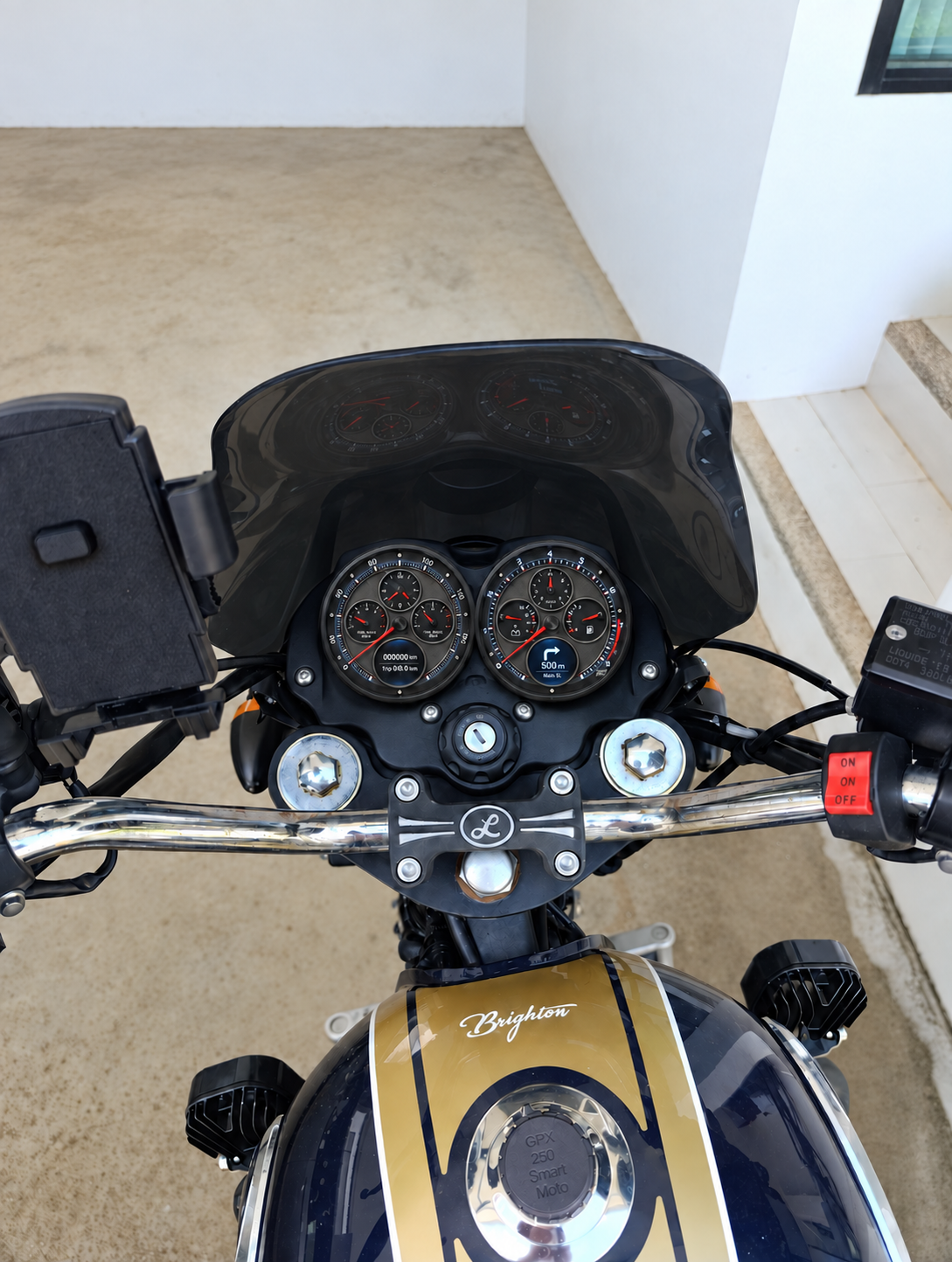
The cover image is an AI-assisted visualization of the proposed panel on my motorcycle, not a photograph of an installed working prototype. Errors in the renders were introduced by AI; scales, lab

Real needles, configurable displays

Two round instruments will put the main riding information on physical needles. Small round displays will provide additional information and a configurable interface. Each instrument is planned around four gauge motors, with smaller dials inside the main scale.

The exterior concept shows speed, a clock and front/rear tyre pressure in the left instrument; the right instrument shows engine speed, voltage, fuel level and selected gear.

The render is an early visual concept. Errors were introduced by AI; its scales, labels and display graphics are not final. The first block diagram places the speedometer and tachometer on opposite sides compared with the render. This is still being reconciled, and neither image is a manufacturing reference.

Two identical STM32 instrument modules

Each module is planned to contain:

  • An STM32F103 microcontroller.
  • Four gauge motors.
  • A display.
  • A real-time clock (RTC).
  • An ambient light sensor.
  • Its own voltage regulators.
  • Two bright indicator lamps based on high-power LEDs.
  • An RS-485 interface to the main unit.

ESP32 main unit

The main unit will contain the motorcycle interface, power-supply protection, RS-485, an IMU, an external watchdog, BLE for communication with a phone and Wi-Fi.

The ESP32 will handle application logic and generate display content. Each STM32 module will control its local instrument hardware. The intended development environment is the Arduino framework with PlatformIO.
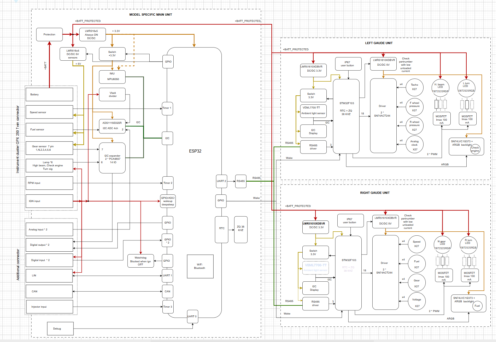
First electronics block diagram
First electronics architecture. Proposed design, not a finished circuit schematic. Open the image for full resolution.

What comes next

The next steps are to refine the mechanical layout, electronics and power management, including keeping the clock running with the ignition off.

Longer-term ideas include estimating fuel consumption from injector pulse durations and combining that with refuelling records from my AI assistant; sending motorcycle condition and route data to a home server; exploring weather along a navigation route and route planning that accounts for refuelling; and displaying phone notifications. These are planned experiments, not working features yet.

Project sources

The public project repository currently contains documentation, design images and a folder structure for mechanical, hardware and firmware development. Native CAD, circuit schematics, PCB layouts and project firmware have not been published yet. I intend to release the design sources and Arduino-based firmware as they mature; a license has not yet been selected.

More images and development updates: dashboard.smartmoto.asia.
  • The displays have arrived — from AI render to real hardware

    Sergei5 hours ago 0 comments

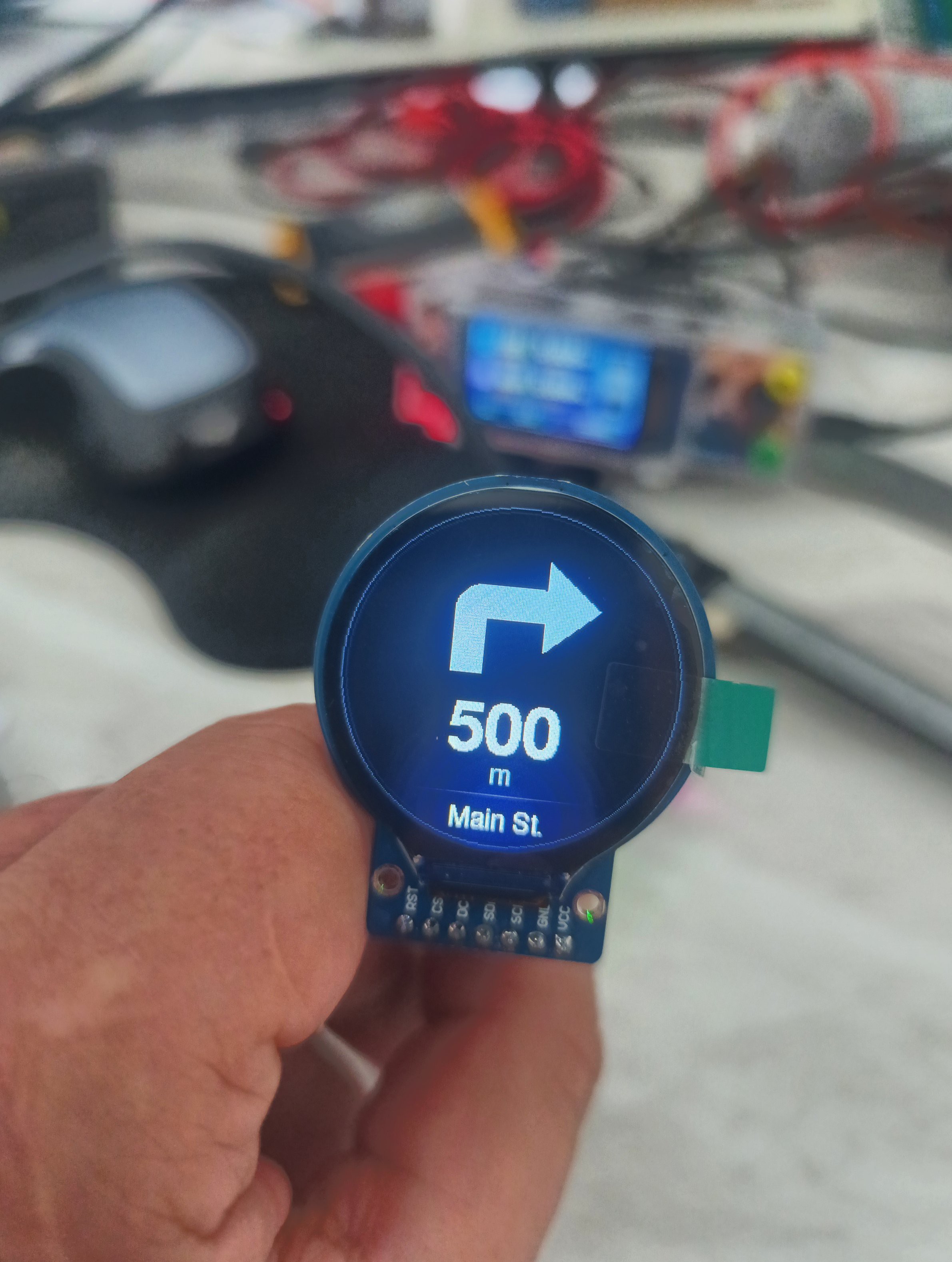
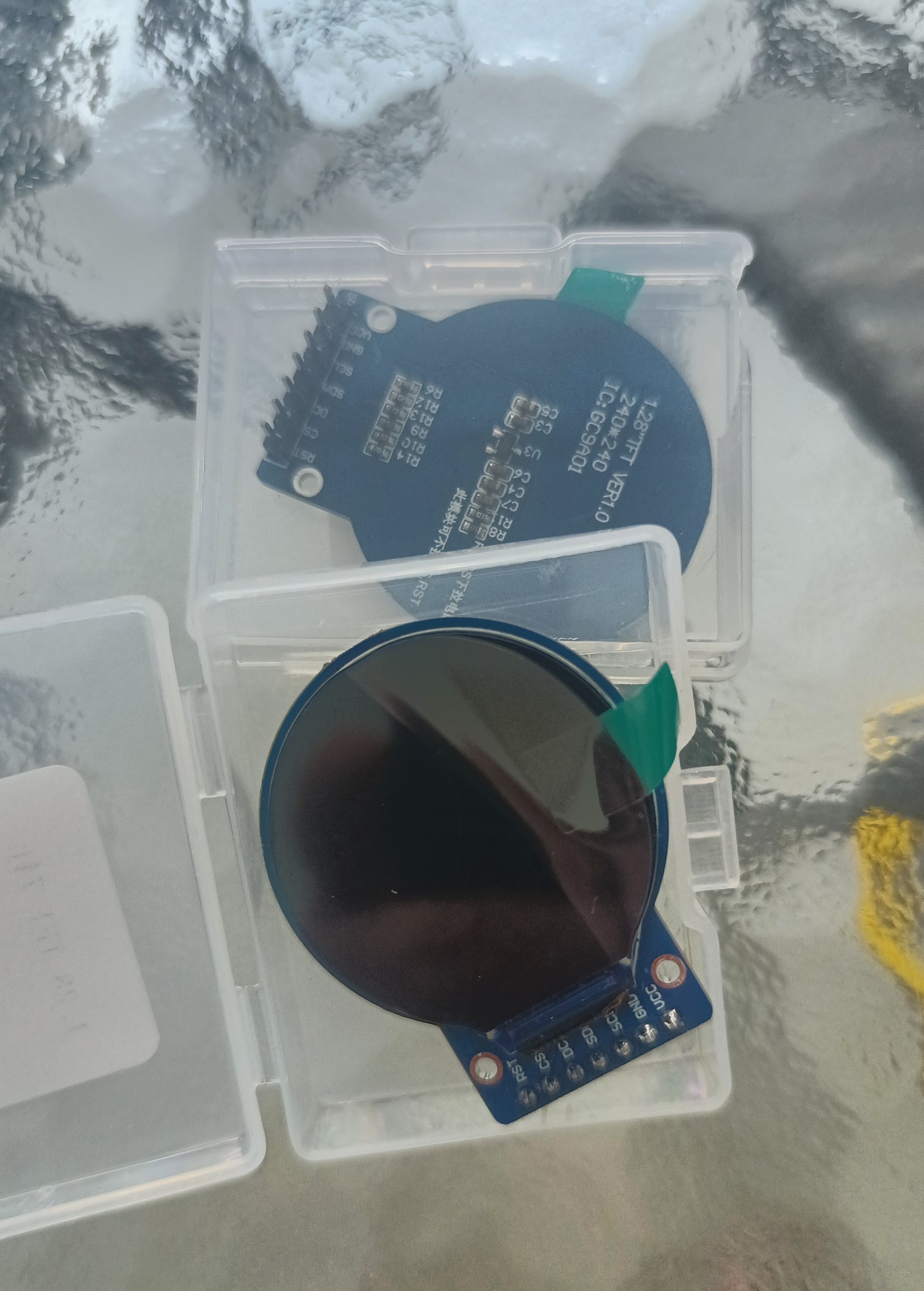
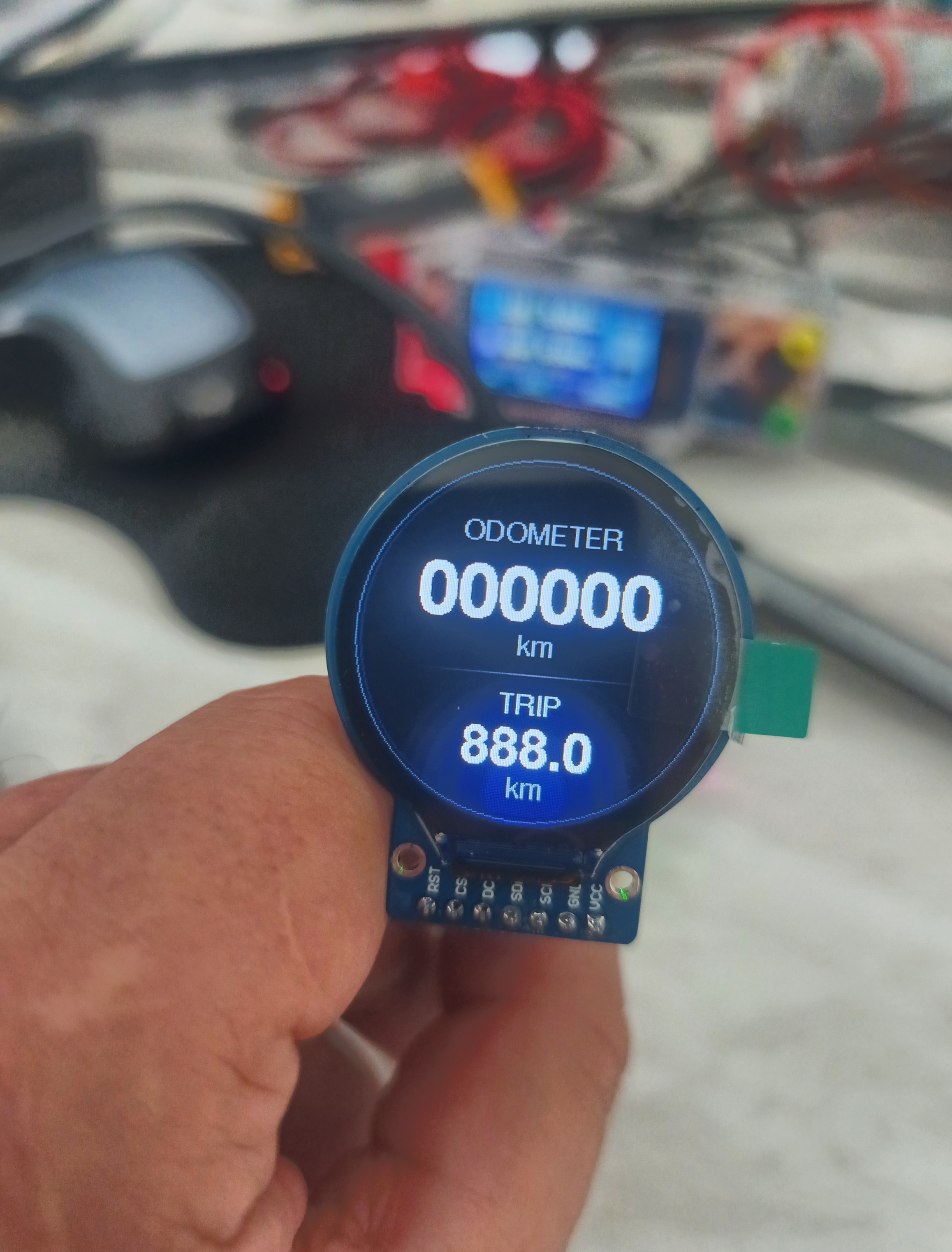
    The displays arrived today, and I couldn’t resist trying out the odometer and navigation prompts on them.

    I grabbed a Waveshare ESP32 development board, connected a display and asked Codex to write the code. Three minutes later, it was working.

    It looks fantastic — just like the AI render, only now it’s real hardware in my hand.

    Odometer and trip display running on the round screen
    The first odometer and trip screen on the real display.
    Navigation prompt with a right-turn arrow and 500 metres on the round display
    A first look at the navigation prompt: turn right in 500 metres.
    The newly arrived round display modules in their cases
    The round displays, fresh out of the delivery box.

    One small surprise: SPI, not I²C

    The displays turned out to use SPI rather than I²C. Not a big problem: I²C was still shown as the display connection in the first block diagram, so that label needs updating. There are enough microcontroller pins for everything.

  • First design results: from real parts to a Fusion layout

    Sergeia day ago 0 comments

    On 20 September 2026, I reached the first concrete results of the instrument-panel design.

    Starting with the most critical parts

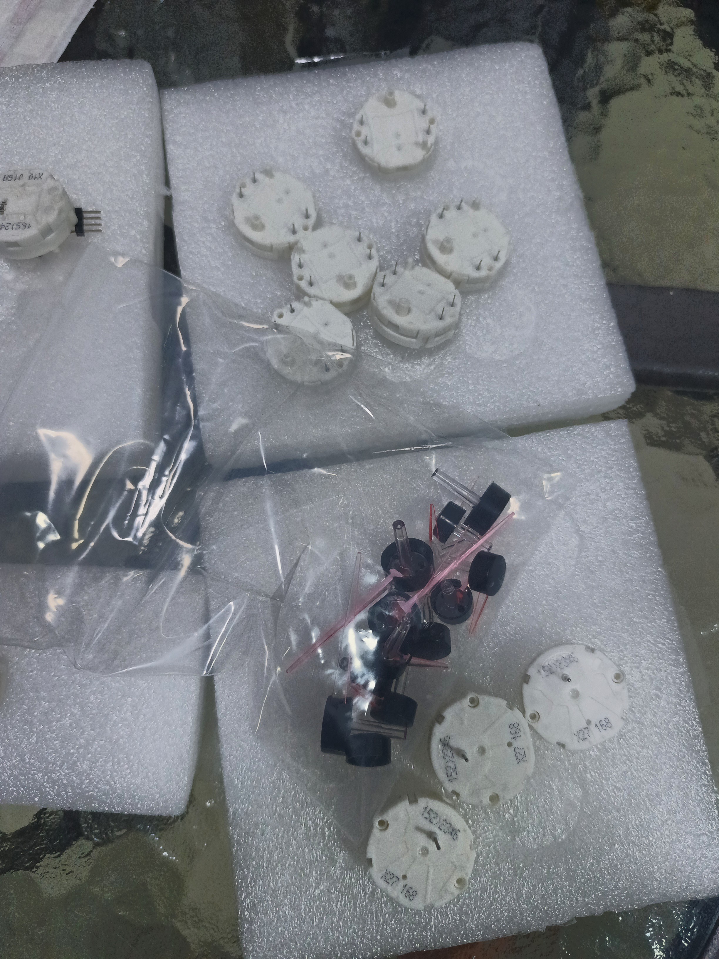
    At the start of development, I received the parts that were most critical to my design: the gauge motors and needles ordered from AliExpress. I wanted to base the layout on the actual components, so I carefully measured them and created 3D models for accurate packaging and mechanical design.

    I also checked that the motors worked using an Arduino and a very simple sketch.

    Gauge motors and needles received from AliExpress
    The actual motors and needles: the starting point for measurements, 3D models and the instrument layout.

    From measurements to a mechanical layout

    Using the measured component models, I put together the first instrument layout in Autodesk Fusion. This lets me work out how the motors, shafts, needles, dial plates and display openings fit together, and check clearances as the design develops.

    The exterior render and both Fusion views are available in the project gallery.

    How the panel could look on my motorcycle

    I then made a visual mock-up to get a first impression of how the new panel would look on my GPX 250 Twin. This is an early look at its appearance and proportions from the riding position.

    Concept visualization of the twin-instrument panel on my GPX motorcycle
    The panel on my motorcycle — an AI-assisted concept visualization, not an installed working prototype.

    A first electronics architecture

    I also drew the first electronics block diagram. The architecture uses an ESP32 main unit connected over RS-485 to two identical STM32F103 instrument modules. Each module has four motors, a display, RTC, an ambient light sensor, its own regulators and two bright LED indicator lamps.

    First electronics block diagram

    Proposed architecture, first version. Hardware and firmware are still being developed.

    What is working, and what is next

    The motors have passed an initial functional check. The complete cluster is still in development, with mechanical refinement, electronics and power management next.

    The renders communicate the intended appearance, but contain errors introduced by AI. Scales, labels and display graphics still need work. The speedometer/tachometer positions also differ between the exterior render and the block diagram; I will reconcile these as the design develops.

    Follow the full development log at dashboard.smartmoto.asia. Documentation and design images are in the project repository.

View all 2 project logs

Enjoy this project?

Share

Discussions

Similar Projects

Does this project spark your interest?

Become a member to follow this project and never miss any updates