 gamadril.dev


Why this device
While reverse engineering the HZ-B500 that I already use in my car, I saw another 7 inch LCD device sold by ALDI as "Smart Display for the car" for 30 €, and I couldn't resist. Sold as BAUHN AIBCP-1225 (ALDI’s private label). The actual manufacturer is unknown. It’s likely an OEM/ODM product that is simply rebranded.
Teardown
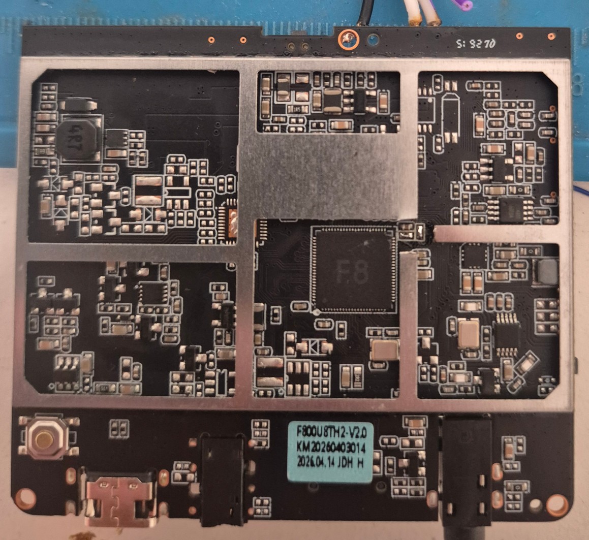
The board inside is very compact and labeled F800-MAIN-V2.0. All components sit under two metal cages whose lids come off without a soldering iron.
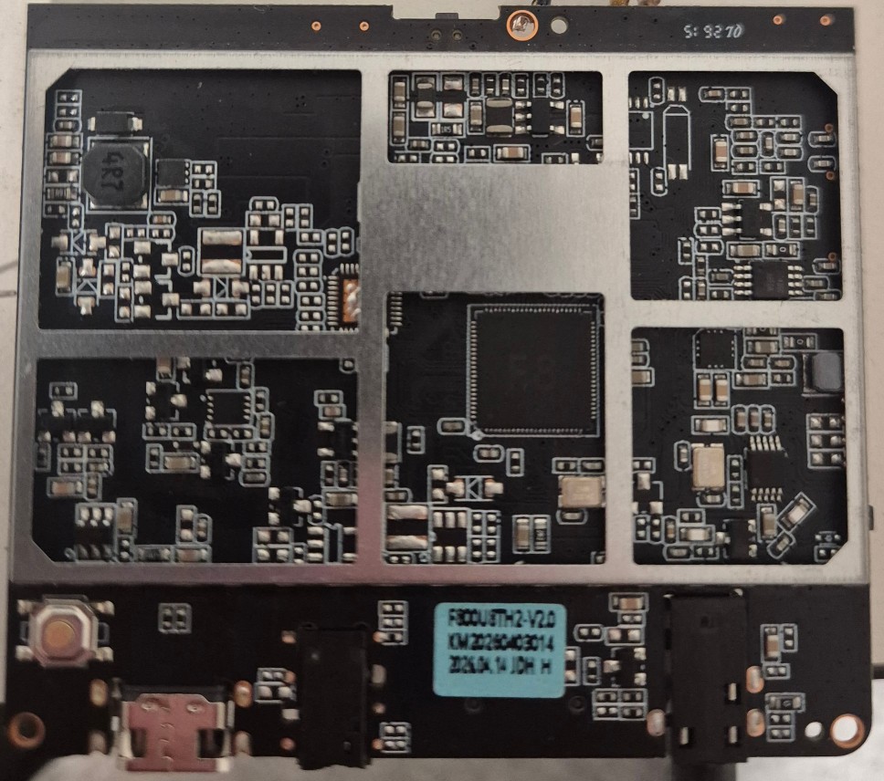
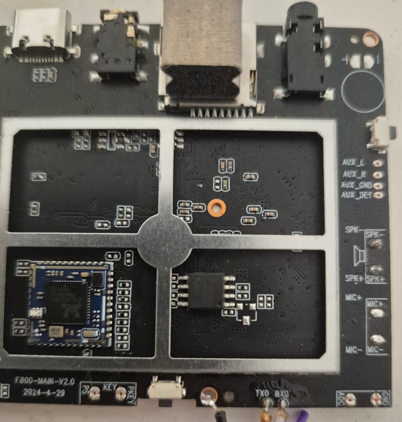
- CPU: the marking is etched away and only "F8" remains. There is no DDR chip nearby, so the memory appears to be integrated into the SoC package. So this is most likely an Allwinner V851S (Cortex-A7 @ 900 MHz, RISC-V @ 600 MHz, 0.5 TOPS NPU), 64 MB DDR2 RAM (from bootlog).
- Storage: 16 MB SPI NOR flash (XMC XM25QH128D).
- Wireless: a combined BT/Wi-Fi module based on the RTL8733BS.
- Other: a power button (not a switch). The mic and speaker cables are soldered directly to the board without connectors.
UART
The board has RX/TX test points on the side, but there was no activity on TX. Tracing showed that the 0 Ω resistors between the CPU and the test points are not populated. Two solder bridges fixed that and the boot log appeared on the UART lines. To access that pads I had to cut out small part of the cage.
Bootlogs also confirm 64MB DDR2 inside.
[40]DRAM BOOT DRIVE INFO: V0.19
[43]DRAM CLK = 528 MHz
[45]DRAM Type = 2 (2:DDR2,3:DDR3)
[48]DRAMC read ODT  off.
[51]DRAM ODT off.
[53]DRAM SIZE =64 M
[55]dram_tpr4:0x0
[62]DRAM simple test OK.
The console presents a login prompt.
FEL mode: the puzzle
From the HZ-B500, the first thing I knew about Allwinner devices was that shorting an SPI flash data line to GND activates FEL mode after no bootable media was found. I did that with MISO, connected the cable, and the boot process stopped, but nothing happened...
The PC saw no FEL device. That surprised me, so I started to investigate.
- Is USB-C power only? I traced D+/D-. There are two pairs of 0 Ω resistors, all present, and the connections to the USB0-DM/DP pins of the CPU are intact. The missing CC resistors could explain problems with USB-C-to-USB-C power, but my USB-A-to-USB-C cable powered the board without problems.
- The power button. After more experiments I noticed that FEL mode is entered only while the power button is held down, and disappears when I release it.
So the button only starts the power circuit, something has to latch it on after boot. In FEL only the BROM runs, and nobody does that.
The power-hold pin: PH0
I dumped the flash in FEL (holding the button) and analyzed the bootloader.
The result:
- boot0 does this as the very first thing in its main function: it sets PH0 as an output (
PH_CFG0at0x02000150) and drives it high (PH_DATat0x02000160, bit 0). - The 4.9 kernel does the same through a
sys-powerdriver, from the device-tree nodesys_powerwithgpios = <&pio PH 0 …>.
So the "boot stopped, FEL not entered" symptom was FEL running only while the button was held. Holding the button, I could latch power by hand:
sunxi-fel writel 0x02000150 0x1    # PH0 = output
sunxi-fel writel 0x02000160 0x1    # PH0 = high
After that the button can be released and the FEL device stays on USB. sunxi-fel -l shows:
USB device 003:086 Allwinner V853 [chip ID redacted]
FEL reports V853 because the V851S and V853 share the chip ID, so this identifies the family but not the exact part.
SD card FEL switcher
Because the SD card has a higher boot priority than the NOR flash, a small SD-boot SPL would jump directly into FEL like on F133 device. It was adapted from the d1s-melis-tools toolkit to this CPU, and it now asserts PH0 at the start of the reset handler, before stack setup, so the board stays powered after releasing the button.
F800-linux-tools
Extracting the partitions from a flash dump is possible with existing tools, but I like having everything in one place, as in...
Read more »

 isaacporras
 ct

 Grégory Paul