• Debugging WCH RISC-V chips with plain CMSIS-DAP: an emulated JTAG DTM

    Armin van der Togt • 21 hours ago • 0 comments

    Debugging WCH RISC-V chips with plain CMSIS-DAP: an emulated JTAG DTM

    One goal of OpenMUPP (Open Multi-architecture Universal Programmer & Probe) is one probe for many target families. The host must not need a vendor USB protocol, a driver install, or a different dongle for each family.
    For ARM Cortex-M, CMSIS-DAP v2 already does this. It uses WinUSB, so Linux, macOS and Windows need no driver. probe-rs, mainline OpenOCD and pyOCD support it.

    WCH RISC-V chips are a different case. The range goes from the very cheap CH32V003 to the CH32V20x and CH32V30x.

    The problem with WCH tooling

    To program and debug a WCH RISC-V chip, you usually need a WCH-LinkE. The WCH-LinkE is cheap, but it uses a WCH-specific USB protocol. The host then needs the WCH fork of OpenOCD, or a tool that knows the protocol: wlink, minichlink, or the wlink driver of probe-rs.

    On the target side, WCH does not use JTAG or cJTAG. WCH uses its own serial debug interface (SDI):

    • One wire on SWDIO, for the CH32V003 and the CH32V00x.
    • Two wires (SWDIO and SWCLK), for the larger chips such as the CH32V20x.

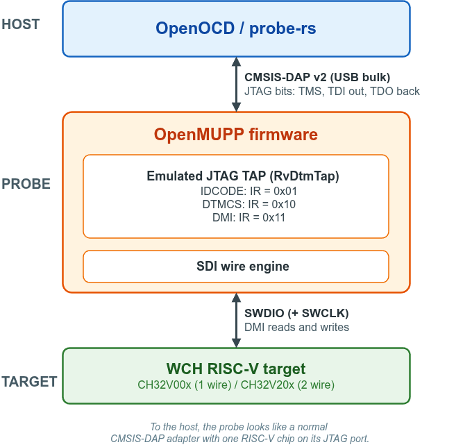
    Both variants give access to the standard RISC-V Debug Module through the DMI (Debug Module Interface). The OpenMUPP firmware has personalities: each personality makes the probe act as a different type of probe. A separate wch-link personality makes the probe act as a WCH-LinkE in RISC-V mode, so wlink and minichlink work with it. But that path keeps the WCH USB protocol, the tools that know it, and a Zadig WinUSB driver on Windows. So the cmsis-dap personality also has a bridge from CMSIS-DAP to SDI. With the bridge, the standard tools and the standard driverless USB interface work for WCH chips too.

    How the bridge works

    The idea

    OpenOCD and probe-rs already know how to debug a RISC-V chip over JTAG. The RISC-V Debug Specification 0.13 defines how, and many RISC-V chips use it. The WCH chips only have a different wire.

    So the probe pretends to be such a chip. To the host, the probe is a normal CMSIS-DAP adapter with one RISC-V chip on its JTAG port. In reality, no JTAG pins move. The firmware reads the JTAG bits from USB, finds the debug accesses in them, and sends each access to the WCH chip over SDI.

    JTAG in five minutes

    Only a small part of JTAG is used in the bridge. A simple explanation:

    • Signals. JTAG has a clock (TCK), a mode signal (TMS), data in (TDI) and data out (TDO). On each clock, the probe sends one TMS bit and one TDI bit, and gets one TDO bit back.
    • State machine. The TMS bits move the chip through a fixed state machine of 16 states. The probe uses it to select what happens next. The states in this post are Shift, Capture and Update.
    • Registers. The chip has one instruction register (IR) and several data registers (DR). The IR value selects which data register is connected between TDI and TDO.
    • A scan. In a DR scan, the chip first copies the selected register into a shift register (Capture-DR). Then the probe clocks the bits through it (Shift-DR): new bits go in on TDI, and the old bits come out on TDO. At the end, the chip takes the new value (Update-DR).

    So one scan writes a value and reads a value at the same time. Capture gives the read value, and Update applies the written value.

    CMSIS-DAP has commands that send raw TMS and TDI bits and return the TDO bits (DAP_JTAG_Sequence and DAP_SWJ_Sequence). OpenOCD and probe-rs use them for RISC-V. The firmware does not need to know which tool sent the bits. It runs the same state machine as a real chip, bit by bit (cmsisdap::RvDtmTap).

    The three registers

    The RISC-V spec calls the JTAG part of the chip the Debug Transport Module (DTM). It has three registers that matter. The IR is 5 bits wide, so it holds values from 0x00 to 0x1F. The firmware decodes these three:

    IR

    Register

    Content

    0x01

    IDCODE

    0x15653101. The host reads it first to find the chip.

    0x10

    DTMCS

    The DTM version (spec 0.13), the DMI address width (7 bits), and the idle clocks that the host must wait after each access...

    Read more »