-
1Instructions for build
This picture is of my "indoor" seismometer, with its electronics in an antique wooden box next to it. It is networked and completely functional, but because of its noisy indoor location, it is not useful for any serious seismology. It is never quiet, even at night, because of vibrations related to air conditioning or heating fans, dog activity, weather, etc. Things DO go bump in the night, a lot, and I have proof... The center mass is an agate sphere, in keeping with the geological aspect of this project.
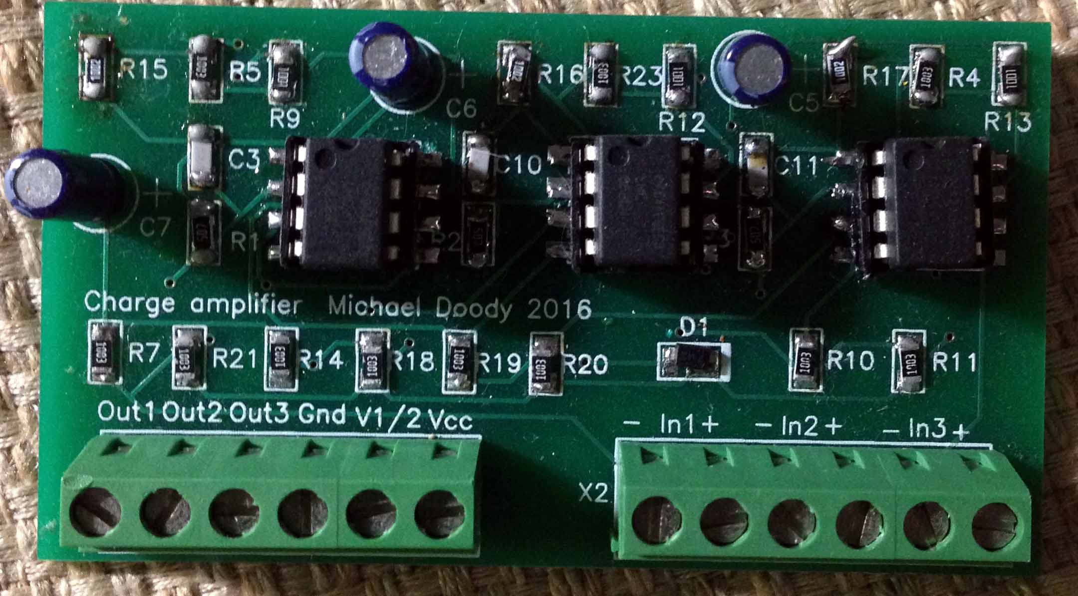
The basic device design consists of a heavy and rigid wooden base, mechanical supports for piezoelectric sensors, a spherical center mass, the sensors themselves, a high quality but very simple 3 channel charge amplifier based on an ultrasensitive Texas Instruments femtoampere op amp, a clock module, the Arduino YUN microcontroller and its program and an enclosure. Because the YUN has built in wireless networking, the data stored on its SD card can be accessed for processing externally, even remotely from the web. The "indoor" seismometer is enclosed in a glass display cloche, to minimize temperature and air current variations. "Working" seismometers are enclosed in weighted styrofoam coolers.
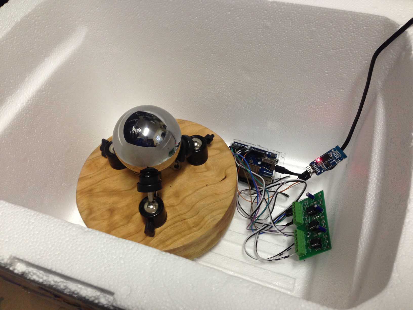
The photograph above shows one of the devices, the Yun board (left), the clock module (middle, with the LED) and the three channel charge amplifier (right).
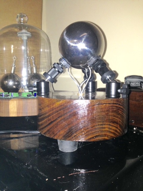
The next photograph shows another device with a heavy 4" walnut base, a 4 pound chromium steel ball and rubber feet. The device behind it is the last version of an earlier design that used 3 steel balls suspended from a center post. It is no longer in use. The single mass design makes fewer assumptions about the vertical component of the seismic noise. It would also be much more stable in case of a strong seismic event.
![]()
Two of the noise vector devices in their styrofoam containers rest directly on a massive 2-car garage concrete slab. The containers are weighted on top.
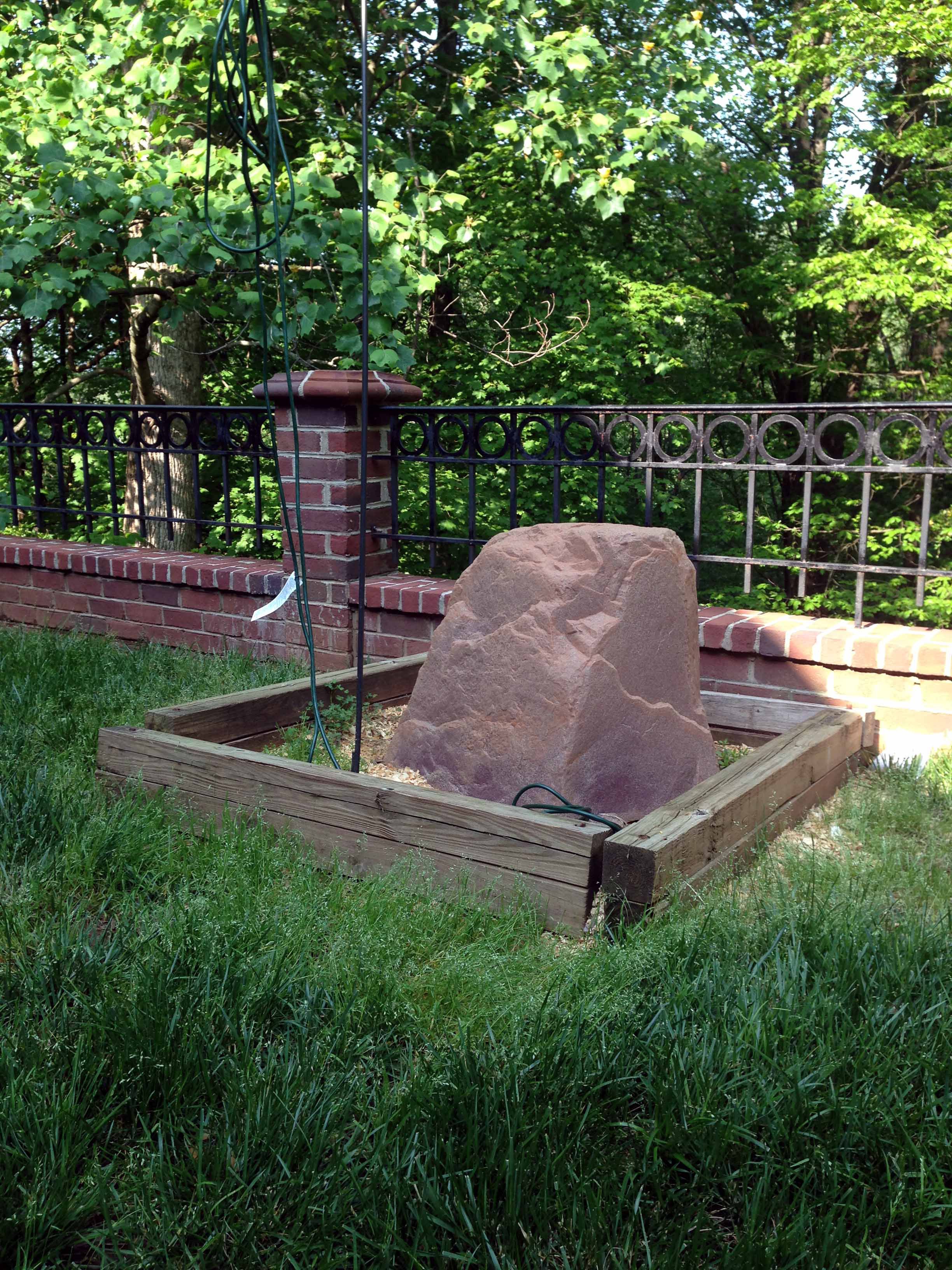
One device is bolted through its styrofoam container to a 300 pound poured concrete base outdoors, under a weatherproof "fake rock" fiberglass housing. As with the others, it is connected to the home network through a wireless router.
I have used several different hardwood bases - walnut, spalted maple and cherry. Different sizes and shapes are possible, but a circular base 2 inches thick and 8 inches diameter seems to work well. Beautiful pieces of wood can be purchased on Amazon - look for "bowl blank". Rubber stoppers (hardware store, usually next to the corks) work well as pedestal bases.
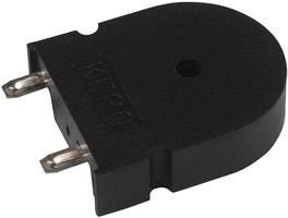
The sensor elements are basically piezelectric buzzers in plastic cases similar to this
![]()
The center hole of the piezo casing is drilled out to allow a hard plastic bead (JoAnn fabric store) to contact the piezo element directly.
The sensor elements are glued directly to adjustable supports. Magnetic door stops (Lowe's, Home Depot) work well like those used for the "indoor" machine above, as do inexpensive mini tripod mounts like these on eBay.
![]()
The adjustable supports are bolted to the wooden base by 1/4" threaded bolts (hardware store) that have been cut to size with a Dremmel tool.
The center mass ball is supported by the 3 beads in the center holes of the sensors and the sensors are tilted at a 45 degree angle with respect to the horizontal. Beautiful minerals and rocks are easily available from multiple sources on the web as 3 inch spheres, as are chromium steel balls.
![]()
The sensors themselves must be precisely angled and leveled - this is extremely important, as the acceleration of gravity is a very significant part of the program's vector calculations. The gravitational acceleration of the center mass must affect all three sensors equally. Smart phone apps like iLevel (for the iphone) can provide highly accurate leveling and tilting information. A bubble level or smartphone is used to level the wooden base.
Inexpensive large scale manufacture is needed to produce a device for use in the third world. A molded plastic base incorporating all the necessary angles and distances without the need for adjustable elements would be the way to go. Glue the sensors in place, drop a lead or steel ball in and it would be done. Someone with a 3D printer could produce a prototype - anybody interested?
Pad2Pad is a company that will custom produce circuit boards at rock bottom prices from designs produced on their own proprietary software or other professional software.
The circuit board plan designed by me (in the files section of this project) can be ordered by any interested party through Pad2Pad - contact me for further instructions if there is difficulty ordering it or Pad2Pad requires further permission from me. I have spoken with them and this should not be a problem. The design is based on ideas from a Texas Instruments white paper on piezoelectric sensor instrumentation.
The need for soldering might be a barrier to makers interested in building these devices. I am looking into the possibility of selling the charge amplifier PCB board and all of its components on Tindie.com. It will be sold either as a kit with the DigiKey bill of materials or as a pre -assembled board.
Newground.pcb is the Pad2Pad.com project file and it has been uploaded to the uploaded files section of this project. The Pad2Pad design program itself is free and downloadable from their website - it is needed to work with, view or modify the Newground.pcb file.
![]()
The Pad2Pad.com BOM is also included in the uploaded files section of this project and it is also part of the Newground.pcb file. The Findchips.com web page suggested by Hackaday will not accept the BOM in the Pad2Pad format or open source Open Office format, unfortunately. I tried!The PCB is a surface mount design but uses fairly large (well, large for surface mount, anyway!) SMT 1206 components for the most part. Some soldering skills (or patience and willingness to learn!) are required for assembly.
The 3 channel charge amplifier and low-pass filter electronics are based on the following simple design. Shown is one channel only, but they are identical. The TI op amp is a dual design, so only 3 relatively inexpensive op amps are needed.
The Arduino YUN program (906 lines, including spaces and comments) is open source and it is available in the downloaded files section of this project description.
Device for Seismic Noise Analysis
Could a digital device to analyze the statistics of the magnitude and 3-D origins of seismic noise predict some local earthquakes?
 Michael Doody



Discussions
Become a Hackaday.io Member
Create an account to leave a comment. Already have an account? Log In.