davedarko
-
Needs moar research
05/04/2017 at 22:05 • 1 commentI can't believe that I'm so close already... but I do need to check the timings and need to find out if I can advance the code more. This needs to be connected to an analyzer.
![]()
-
Hardware setup
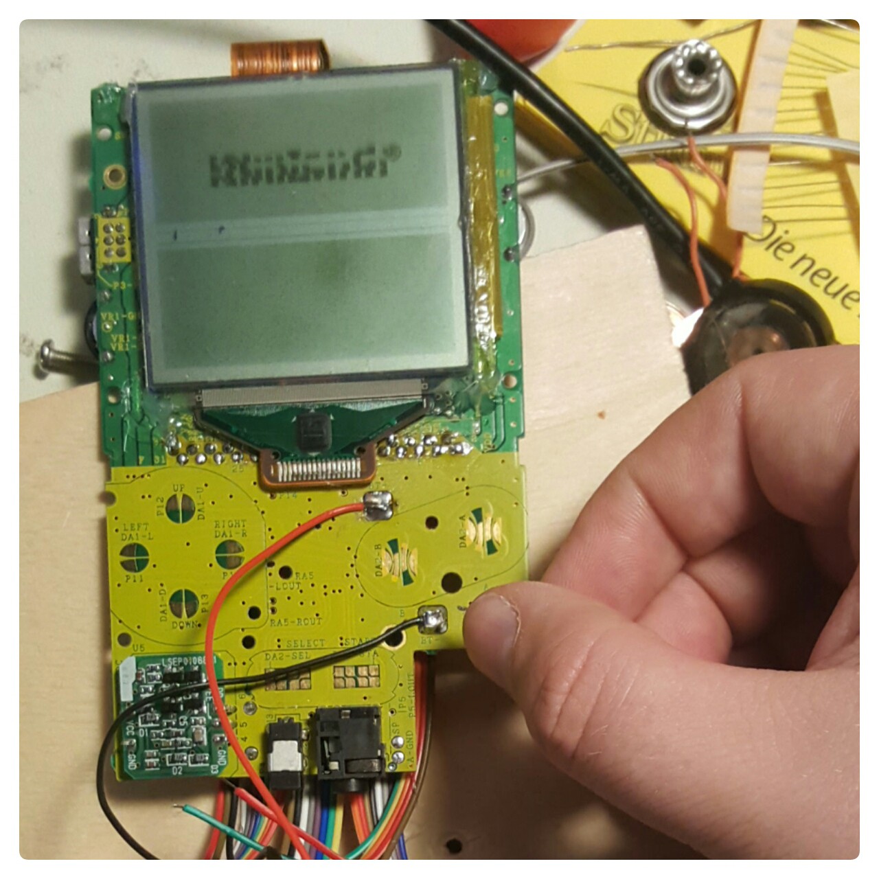
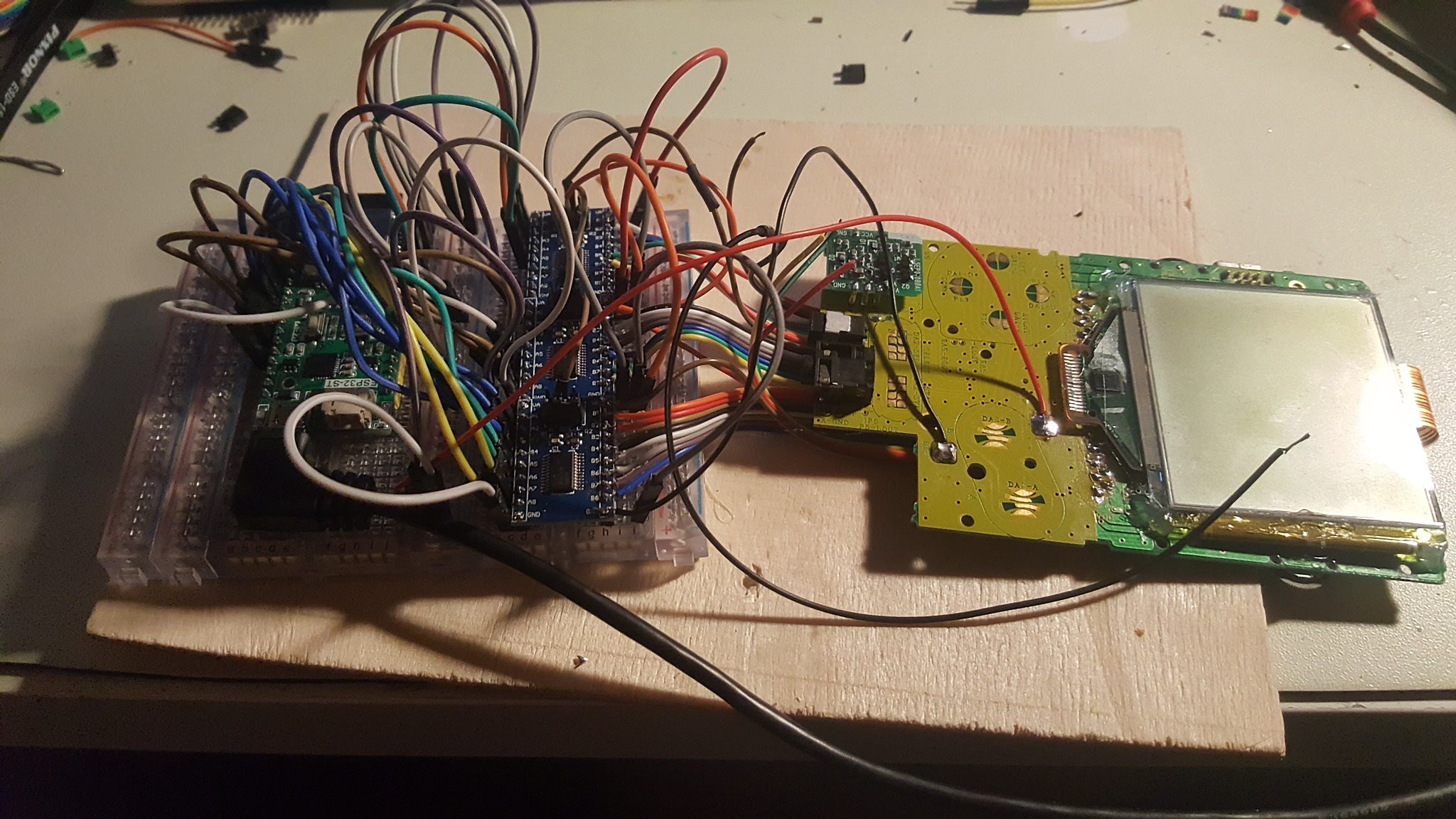
05/01/2017 at 20:52 • 0 commentsI'm still missing some cables, but so far it is looking quite interesting. I've recycled a donor board, replaced the missing switch with a wire, supply the game boy off of the 3V3 power of the esp board through a diode and soldered 32 cables to the missing cartridge port.
![]()
-
what a week - no end in sight
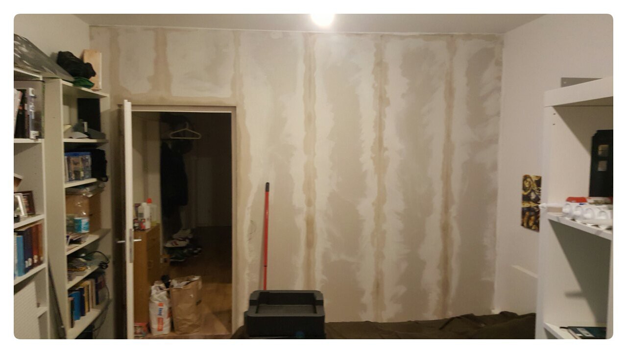
04/22/2017 at 19:37 • 3 commentsThe whole week was filled with work - taking support calls, fixing bugs, meetings and more support calls. In between all that we tried to develop the important stuff. Yesterday, after work, I prepared my room for some dry wall construction ,to close the window between my room and the kitchen. Today I was mainly helping my father to build up the dry wall. The next few days I will be painting, letting it dry, glue on wallpaper, letting it dry, putting paint on the wallpaper and letting it dry as well. To make the Wohngemeinschaft great again. My bed is right next to the wall, before the wall I was awake when my roommate was.
![]() I need to fix up the light switch as well - I see a Wemos D1 mini soon hanging there too :)
I need to fix up the light switch as well - I see a Wemos D1 mini soon hanging there too :)Anyways. Back to the project - I received all the parts to get prototyping started and I'm excited to begin, as soon as I can possibly do, but not today - I'm tired. Funding looks great, e-begging works :D
-
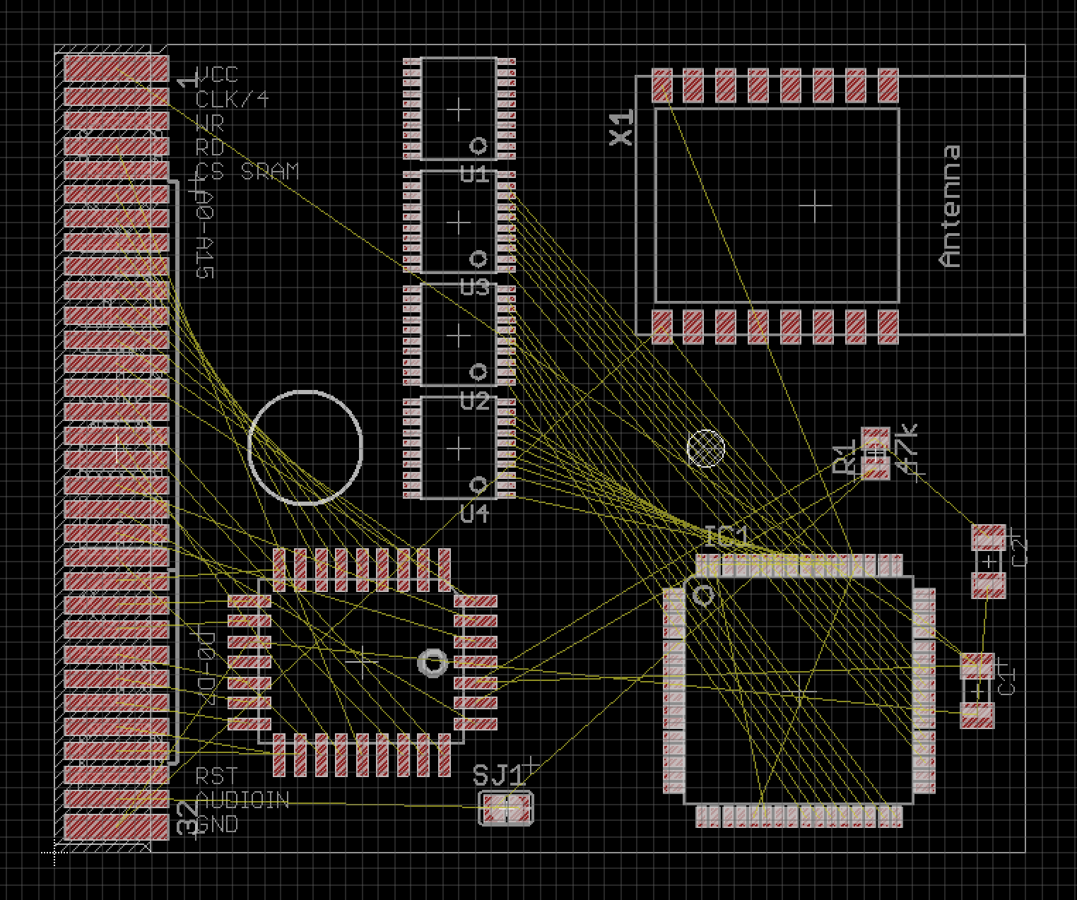
getting closer to a layout
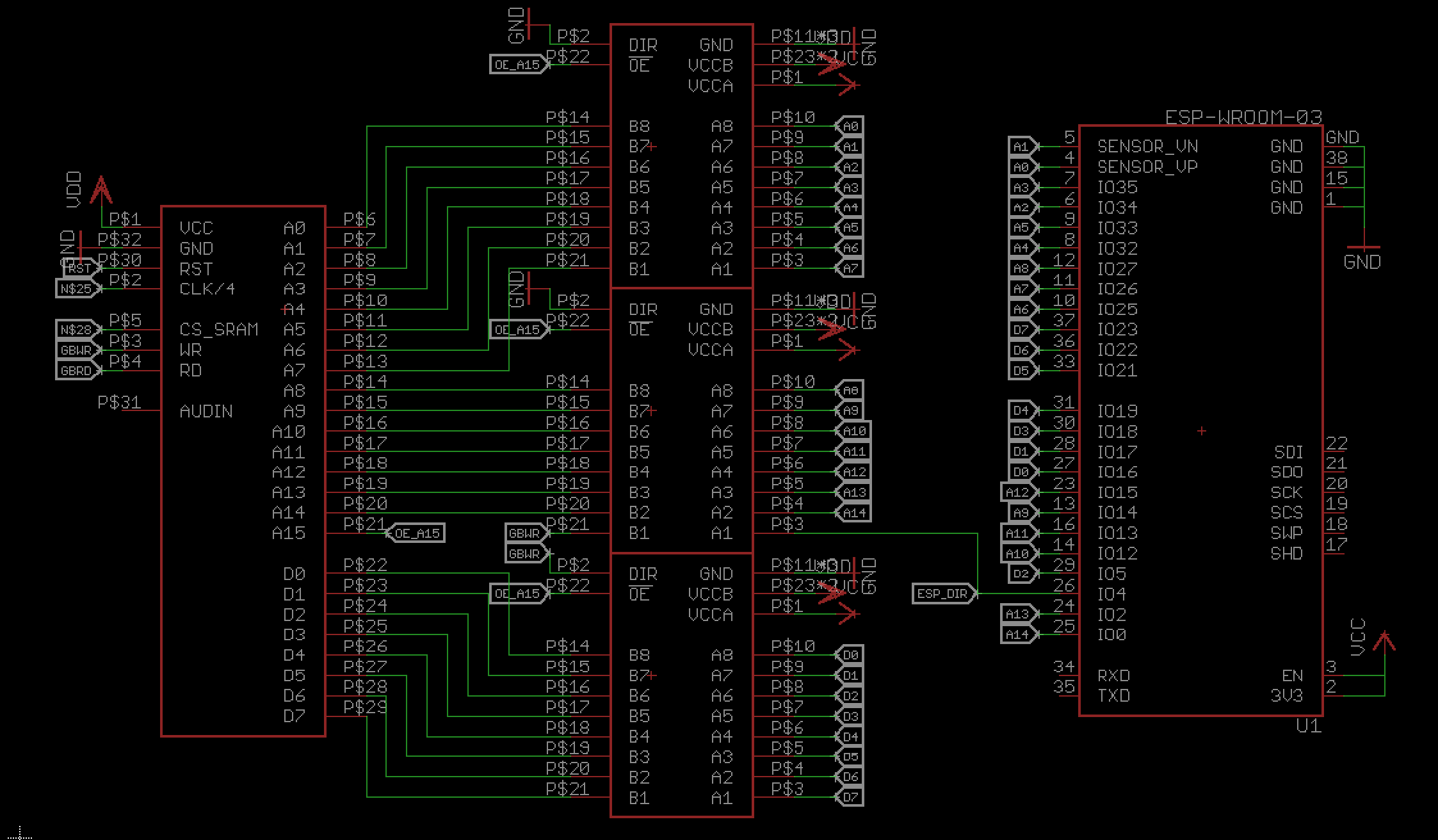
04/19/2017 at 20:54 • 0 commentsI was able to drop a 74LVC8T245 level converter and connect the address pins. A15 on the Game Boy is basically the "chip select" for the ROM / cartridge, when pulled down, since the address space of the 32kb is 0x0000 to 0x7FFF. SO I use that for the output enable pin on the lvl converter.
The Game Boy write pin will define the direction of the data pins lvl converter. The address lines will be pulled low, meaning the direction is always B->A. I use the pin that was previously the A15 pin to tell the ESP the direction of the communication.
A0-A3 are connected to input only pins of the ESP. Not unlike the ESP12F there are some pins that are connected to the SPI flash on the module and shall not be connected otherwise.
So far I only have the RX and TX pin free, but I consider to have the RST line on a transistor - maybe I need to hold the game boy in a reset state for a while, for the ESP32 to boot up and set all pins.
Not on the picture is the current power supply. I'm a bit worried about the two AAA / LR03 batteries in my Game Boy pocket, they're not that powerful in general and with the LED backlight it's not better. Drawing from the 5V switch mode to convert to up to 250mA will be a challenge. I might need to add a LiPo and/or some tantalum capacitors to make it work.
![]()
-
stuff ordered
04/19/2017 at 07:44 • 0 commentsso before I make a PCB and order it for a lot of money (that's almost true, I have a coupon), I thought I buy parts for a lot of money, but hey - there's more money to collect now [http://hackaday.com/2017/04/18/up-up-up-2k-more-seed-funding-for-projects-that-matter/].
Some almost breadboard friendly 74LVC8T245 were ordered, although they have their pinheaders upside down. [http://www.ebay.de/itm/302193394421]
I have an ESP32 basic adapter board (dual row headers, no power converting), but I'll wait on the breadboard adapter I've ordered, with all the bells and whistles. (full disclosure, I wrote balls the first time)
With that the 20bugs on that project are almost spend :) but it's good to have it. There are also two #Hornbill in the making, but they arrive much later.
-
esp32 acting as cartridge
04/18/2017 at 14:46 • 2 commentsi would need 4 SN74LVC245
- 2 for the 16bit address port
- 1 for the controls
- 1 for data, where the direction could be controlled by the read/write pins
![]()
-
PINs and timings
04/13/2017 at 12:39 • 2 commentsthere are still some issues left to solve on my #Game Boy Cartridge plus Programmer project, that I want to solve this weekend [proud moment]. After that I will pin down the hardware. maybe an atmega32 would be an option as well for the "SRAM" part, but a faster atsamd21 seems more reasonable.
https://www.insidegadgets.com/2011/04/23/emulating-the-nintendo-logo-on-the-gameboy/
this tells me I should be safe with an ESP12 as an MBC1 controller. I need 8 pins for the cartridge and 3 for SPI to control the AVR. I don't need the data pins to be connected, I can use the AVR for that.
The next thing would be the SRAM. This will be handled by an ATSAMD21 / adafruit feather M0 (logger) board. It has 20 pins available, so I won't be able to fake an 8k SRAM. That would take 13 pins for address, 8 data and 3 control pins. Since I also need to connect SPI, I have 17 pins left. I need 11 pins for data and control, that makes 64 bytes fake SRAM.Maybe I can use the ESP to make the AVR read the data pins and switch banks via SPI later.
-
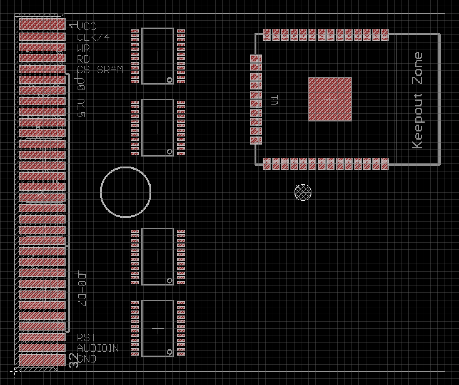
looking for parts etc.
04/02/2017 at 21:02 • 0 commentsStarting from my #Game Boy Cartridge plus Programmer designs, I tried to add some parts and lay them out, to get a feeling for it. I still need power conversion and am thinking about adding a separate power source for the ESP side.
To Recap the Idea:
- the ESP12 will behave like a Memory Bank Controller (MBC) that handles the bus traffic, meaning who is asked for and who will talk (I still hope I have enough pins left)
- the AVR (AT90USB1287) will be connected via SPI to the ESP12 if it is to slow, I could just ask it twice or three times for the value to make sure I have the right data
- the ESP would know that the AVR has to be enabled, instead of the EEPROM, so it needs to be able to enable or disable them
- I need some level-shifting on the board from 3.3V to 5V and the ESP is quite power hungry, so maybe I'll add lots of caps or another battery
![]()