Marcel van Kervinck
-
Subconsciously some logo has snuck into the layout
09/30/2017 at 21:50 • 2 comments![]()
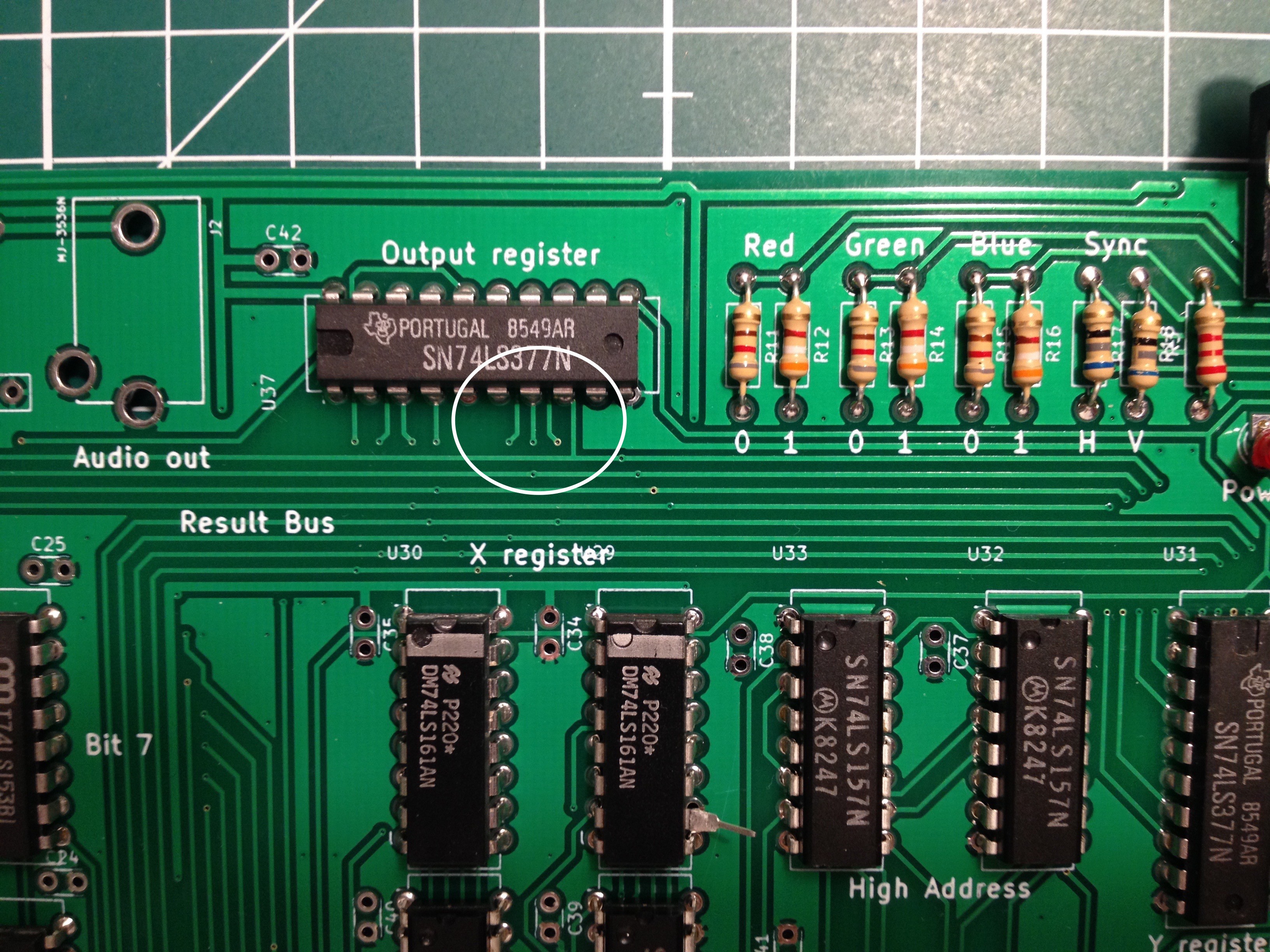
Indeed, the plans to consolidate the breadboard into something more robust begin to materialise.
(And yes, U29's pin 10 isn't soldered due to a little bug.)
-
Getting rid of the breadboard
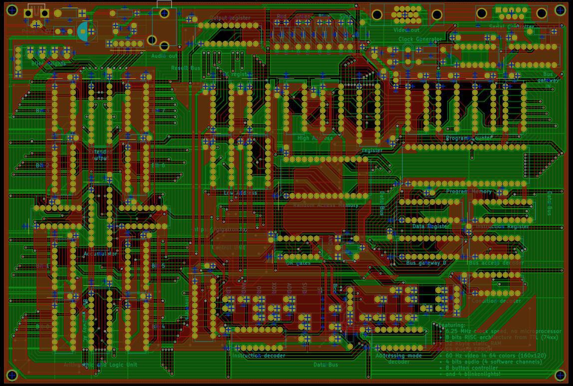
09/20/2017 at 22:39 • 0 commentsFor reliability it is better to solder everything onto a board. So I took the plunge and learnt how to use KiCad. It seems the circuit can be made on a roughly 9x6 inch board, using very relaxed spacing rules. Even if you ignore the time it takes to draw a proper schematic, making a PCB layout took a lot more time than doing the breadboard version. This surprised me a bit.
![]()
Ok, wires are flexible and that speeds things up. Traces are not flexible, and that is why they are more reliable of course. But drawing each segment manually gets harder and harder as the circuit completes. And you don't now if you have to undo major steps until you are almost done. On the other hand, in a breadboard layout you lose a lot of time on debugging wiring mistakes. You win back all that time with the EDA circuit checks, but overall the process is slower.
Perhaps my first PCB shouldn't have been a 144 component, 2 layer monster. But here it is prior to tape-out.
-
Audio output
08/06/2017 at 16:16 • 0 commentsI've been busy adding audio output while trying to keep the component count down. First I figured out a way to insert a second output register into the circuit. It's a 74'273 that takes its input data from the accumulator and the clock from the video hsync. Good enough for 31 kHz software-generated samples and with a bit of luck I can squeeze out 4 voices. I will split this extended output register into 4 bits for audio and 4 bits for blinkenlights.
![]()
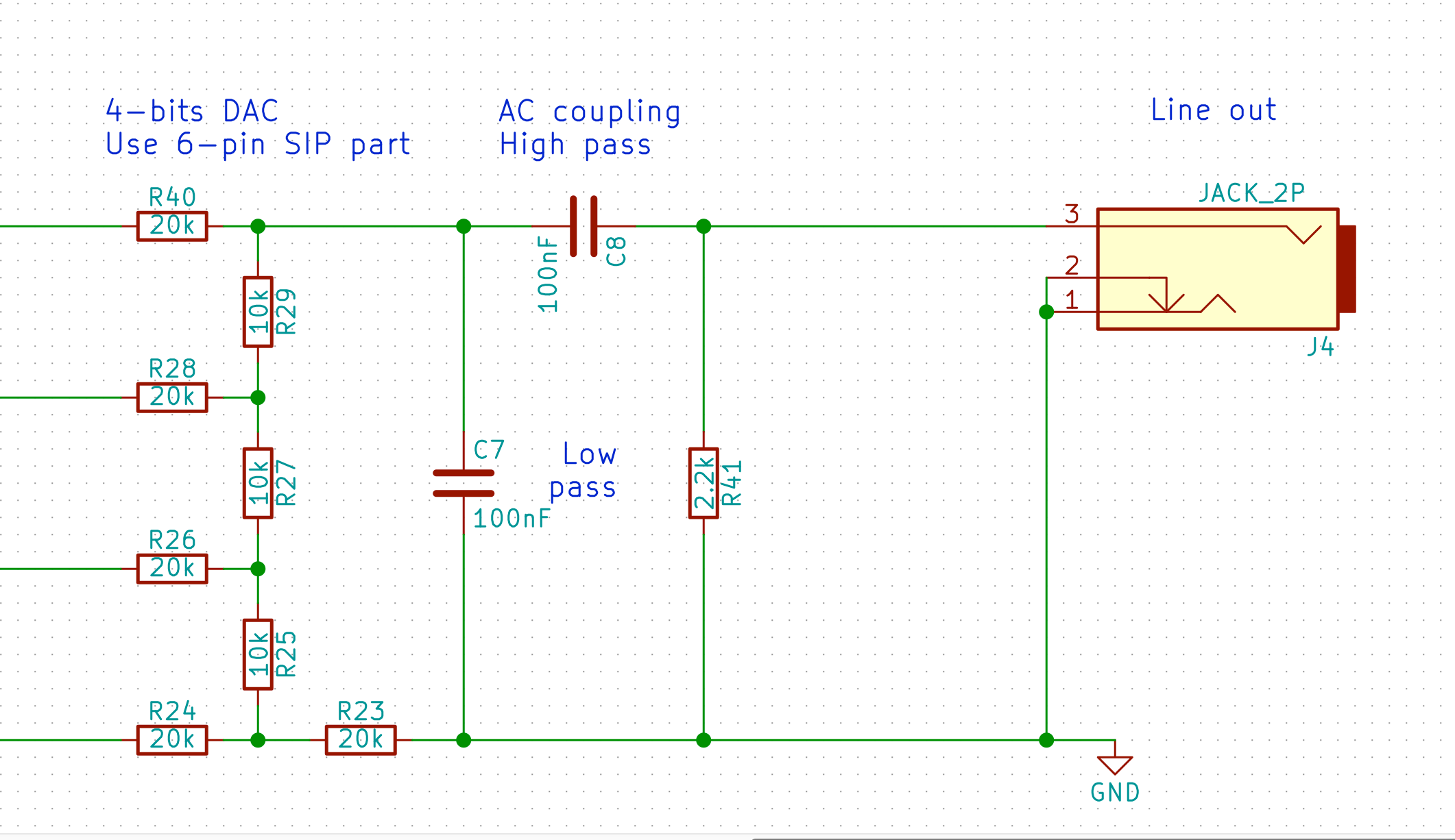
This is the circuit for the audio out part. The idea is that this is good enough to connect PC speakers to. The attenuation from logic level to line level is done by the filters. The calculated output signal should be ok:
![]()
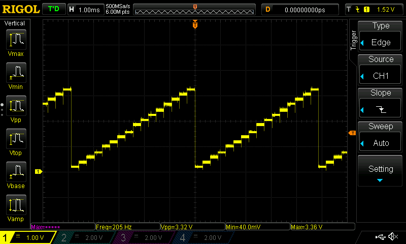
My tests run fine over the interesting audio frequency range. Here's a 555 hiding behind a pot and driving a 74HCT161 that in turn generates a 16-step sawtooth. The DAC is a 10kΩ R-2R ladder whose output gets filtered by the simple RC stage. Overall output impedance is quite high but more than suitable for the PC speakers.
![]()
Close up of the unfiltered DAC output:
![]()
All in all, it seems that I won't need an op-amp for this stage, which is what I was after.
-
Wire wrap sockets meet solderless breadboard
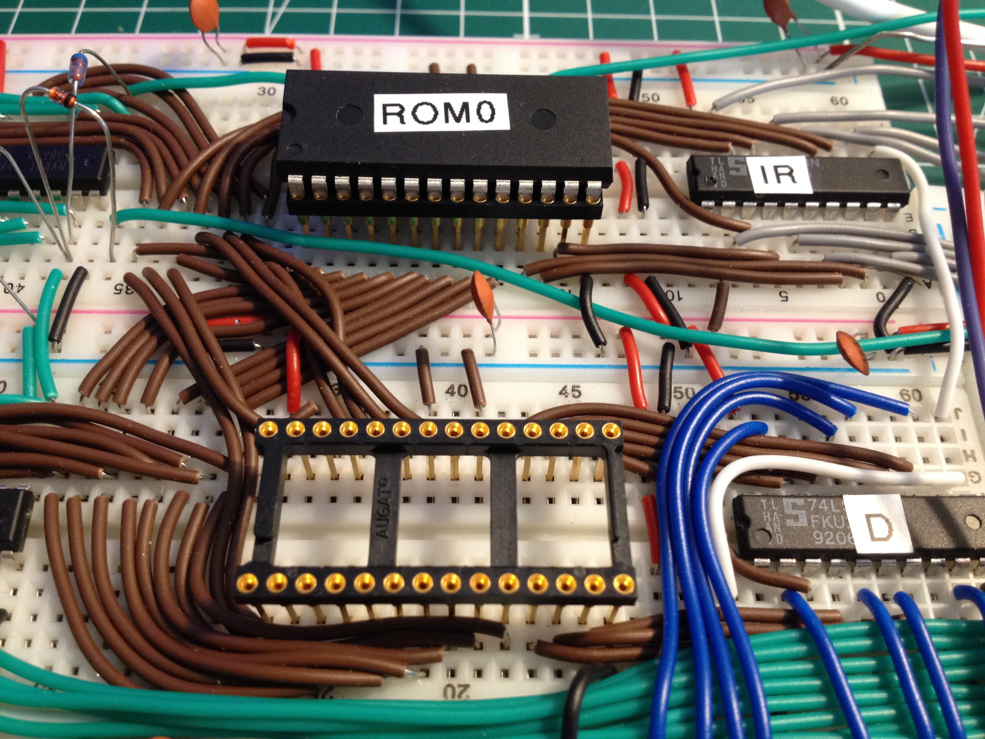
07/02/2017 at 10:28 • 0 commentsAs the programming is done externally, the breadboard suffers from the continuous removal and insertion of EEPROM's, to the point where they barely stay in place anymore. Following a comment in the Hackaday feature, this looks like a promising solution:
These are IC sockets intended for wire wrapping. I just use them for a better mechanical interface to the breadboard.![]()
-
... and a blinking LED
06/13/2017 at 22:44 • 2 commentsToday I realised that no homebrew CPU project can claim completeness without a blinking light. Lacking free output pins (all 8 are used for video), I hooked up an LED to the unused address pin 15, and use that as alternative.
I'm getting into some serious problems with breadboard fatigue in the EEPROM area. One of the ROM's just keeps popping out. The next phase is therefore to document the circuit in KiCad and convert it into a PCB.
[ Spoiler: the display is an older selfie, as witnessed by the incomplete wiring and background. The on-screen LED is just a 3x2 pixel area turning red at the same time as the breadboard LED. The scrolling is smooth in real life, but due to mismatch with my phone, it may appear jumpy. ]
-
Self-awareness
06/07/2017 at 07:38 • 0 comments![]()
-
Undefined opcodes
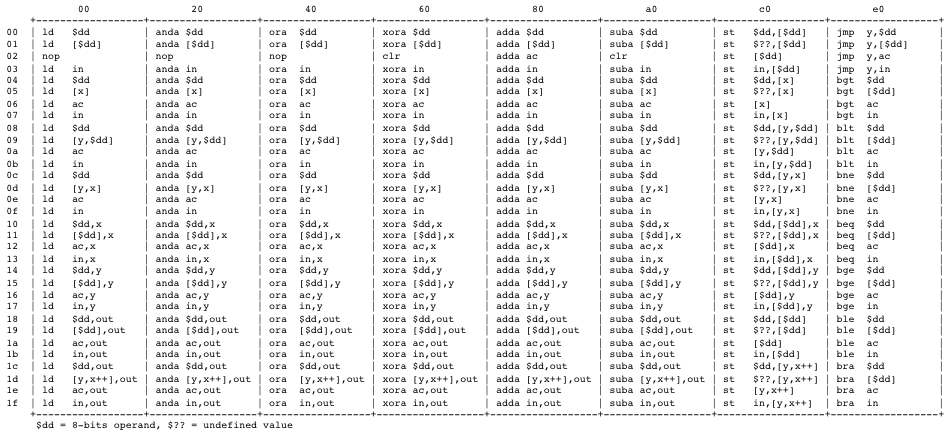
05/29/2017 at 04:54 • 0 commentsFrom the assembler/disassembler it is easy to generate a complete instruction table. Most opcodes result in a valid instruction. Only memory writes while RAM is on the bus result in an undefined value ($??) being stored.
![]()
I found out I had some undefined instructions that are actually very useful. They store a value in memory as well as in X or Y. Their existence is entirely accidental: Unlike AC and OUT, the X and Y registers are not "muted" when we are writing to memory. The purpose of muting is solely to reuse all addressing modes in store instructions, but without destroying the contents of AC or OUT. As X and Y don't have addressing modes that AC and OUT already have as well, I didn't bother to give them an OR-gate that suppresses the enable signal to them ("you don't need these modes").
This omission turns out to be quite useful! Because X and Y are essentially "write-only" registers, each time you use them and you're not sure of their value you have to reload them. Now you can first do a computation, in AC, and then move the result both to X/Y and also back to memory. Both value transfers happen in the same clock cycle. With that, you can easily keep track of what is supposed to be in X/Y in the zero page. I suppose this will be used a lot. I already use it in the video loop.
Now they are no longer undefined. They are part of the family.
-
On the move
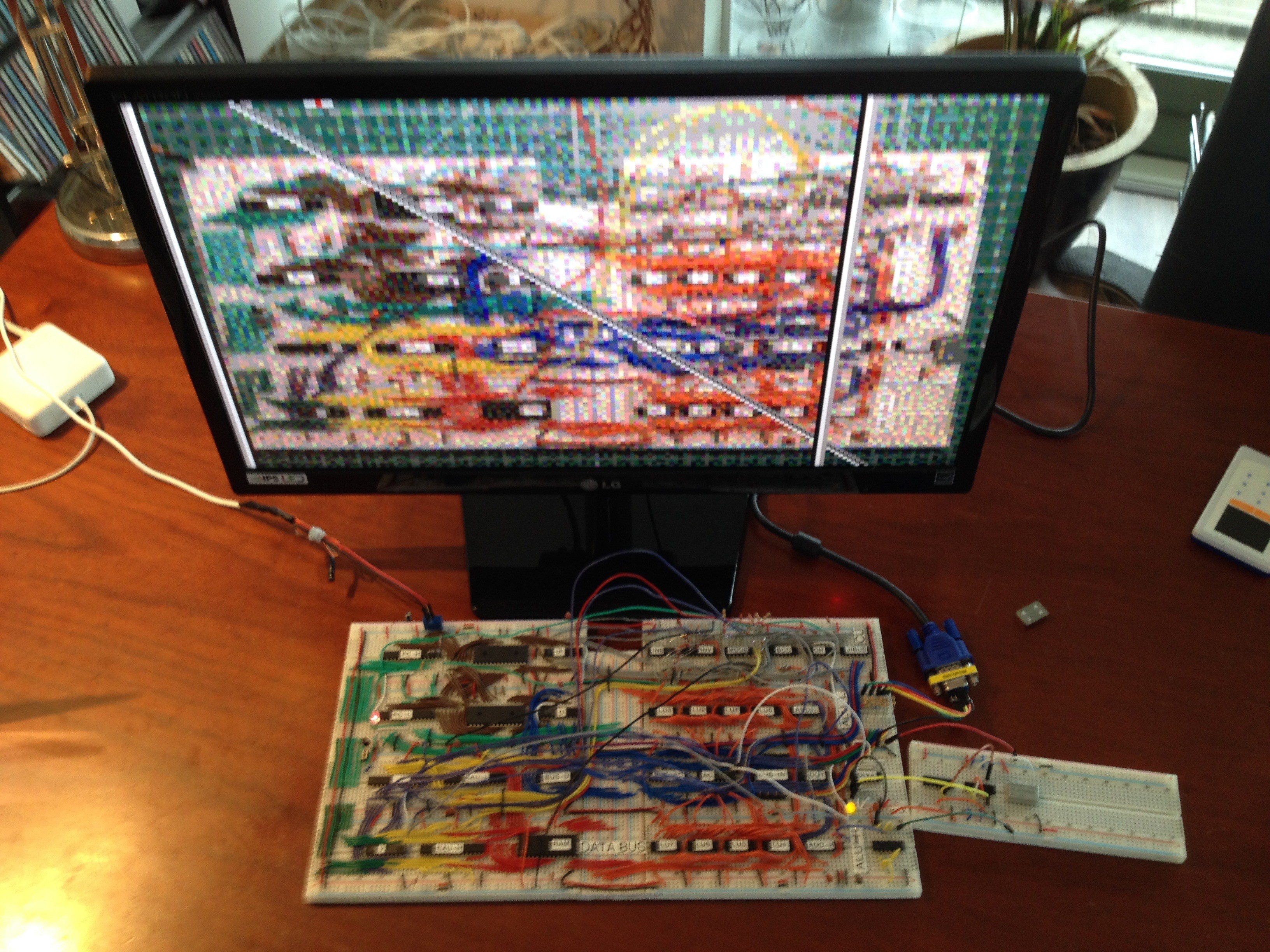
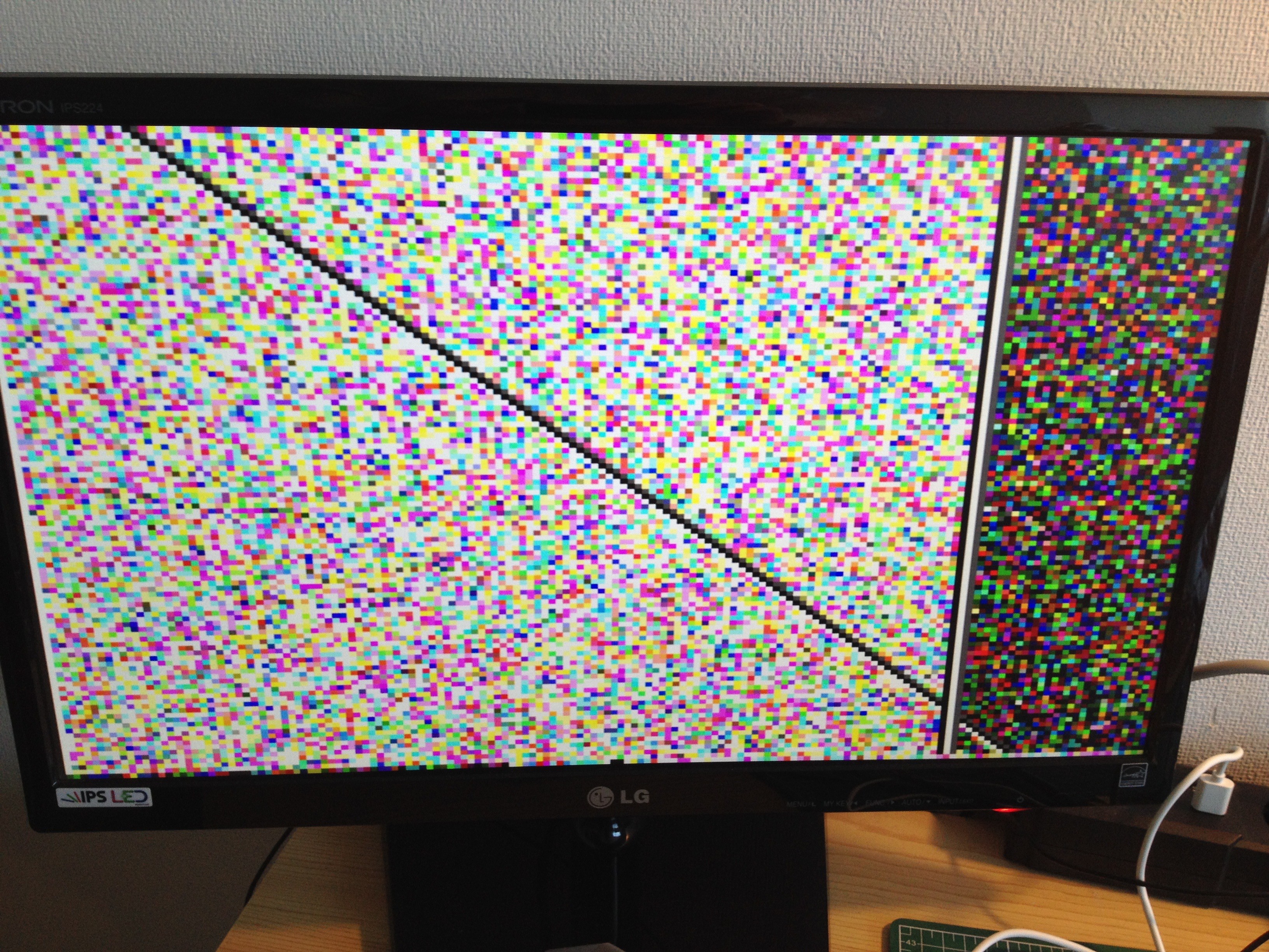
05/28/2017 at 14:06 • 0 commentsFirst moving video output from my breadboard TTL color computer. Again, the test image is just uninitialised SRAM garbage with some lines drawn over it. Line 60 to 90 are scrolling 1 pixel per frame.
The scrolling looks a bit jumpy in the recording, but that is just the mismatch between the camera and monitor frequencies. In real life it is stable and smooth.
-
Stable video with help of a canary
05/27/2017 at 12:33 • 0 commentsThe control unit (CU) uses decoder IC's and diodes for decoding the operation and addressing modes. I'm toying with plain 1N4148 (silicon), 1N60 and BAT85 (both Schottky) diodes. Surprisingly, all seem to work pretty well. Here they are all mixed more or less randomly on the breadboard.
![]()
The diodes between INS (74LS155) and INV (74LS240) form the operation decoding ROM matrix. The diodes connected to MODE (75LS138) pull the control lines for register loads and RAM address generation. The diode mess looks fragile, but in reality it all stays in place rather well.
When combining diodes with TTL, there is only 400mV voltage drop to play with before entering undefined territory. Some of the diode logic outputs travel all the way across the circuit, which means that supply voltage and ground differences must be controlled over that distance. Also, 74LS requires 4.75V as absolute minimum, or no more than 5% drop.
When I installed the supervisory MCP100 some weeks ago, I already noticed that I had to connect the 5V supply on the same segment in order to boot. If I connected it further away, it simply wouldn't release the reset. This means there is too much resistance between the segments, more than the equivalent of 250mV. A couple of extra bridges solves that. But to troubleshoot this, I found a useful second use for the MCP:
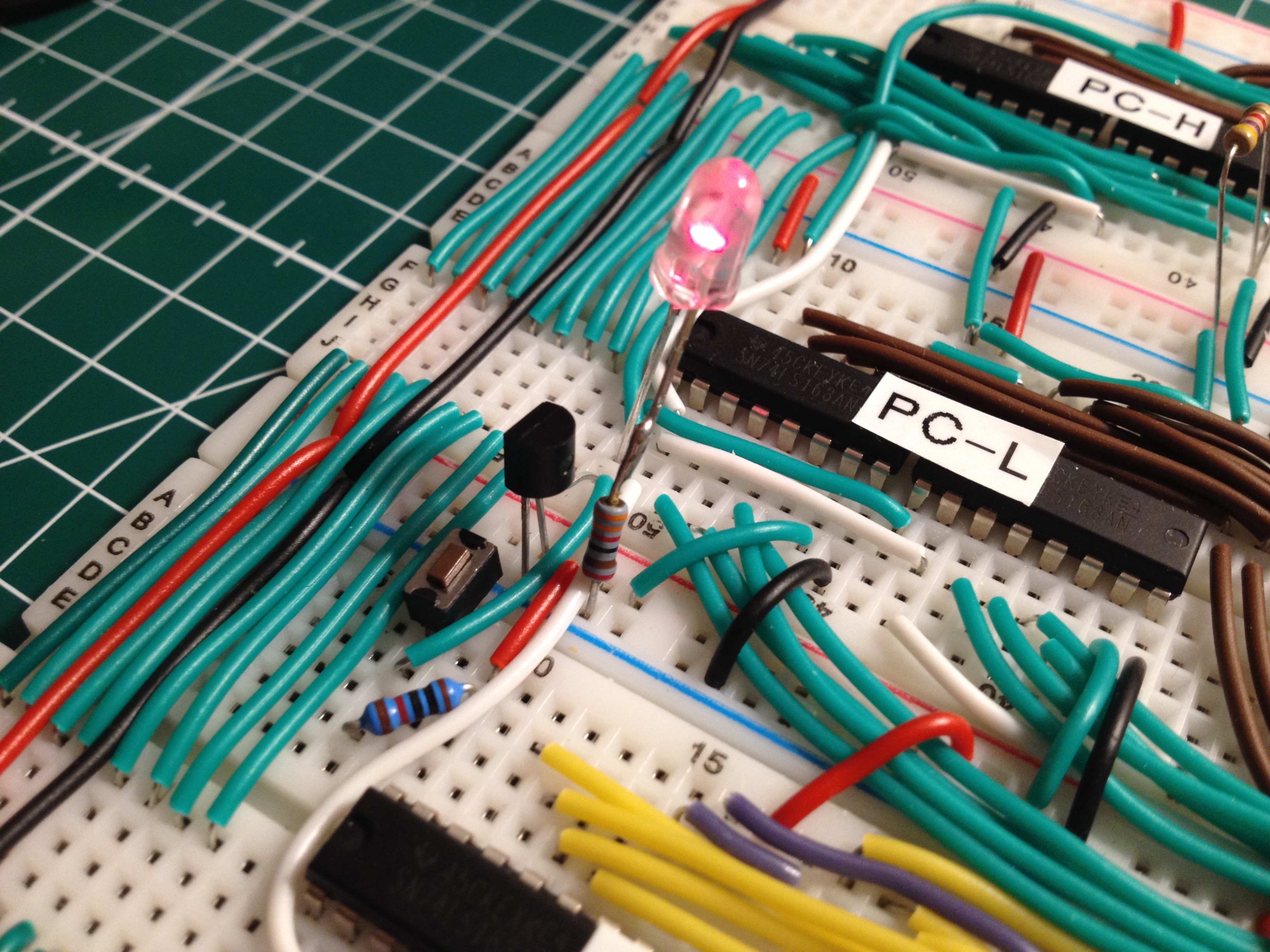
First recall that the MCP keeps the reset line low for as long as the supply voltage is not stable above 4.75V. (Well, the MCP100-475DI/TO does that. In ordering these, every letter means something important). In my circuit it sits next to the reset button, as you can see here:
![]()
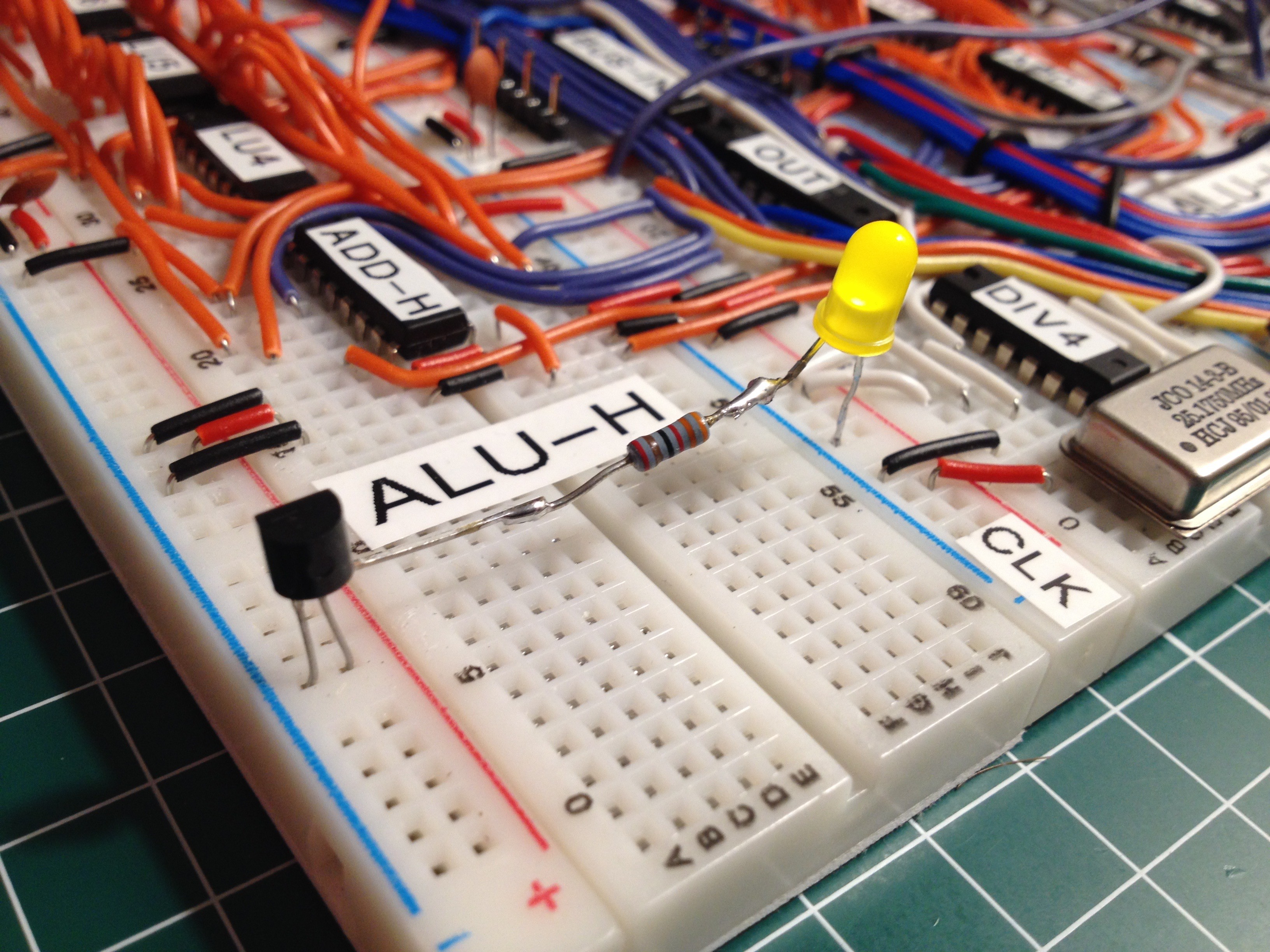
You can spot the reset switch with its 10kΩ pull-up resistor. It controls pin 1, or /CLR, of the PC counter IC's (all four of them). The red LED is just lurking on the reset line as an indicator. The MCP is the three-legged black component that looks like a transistor. It has one leg on the reset line. The other two legs are on Vcc and GND. It is a clever and useful little device. Now it turns out you can make a super easy voltage tester from an MCP, an LED and a current limiting resistor (330Ω), as follows:
![]()
The "reset" leg is now connected to the LED and not to the circuit. If the LED is on, the voltage difference on the supply rails is stable above 4.75V. With this device it is easy to test the voltages everywhere, much easier than with a multimeter or scope. I call this the "canary" because of the yellow light, and because when the light goes out, it signals that that part of the circuit is in danger.
With all voltages controlled, the video image is now stable. I'm still emitting uninitialised SRAM data, but to verify that I'm streaming from the right addresses, I let the CPU draw some lines across the screen, vertically and diagonally. All addressing modes and registers are now exercised, so this is a pretty good system test.![]()
-
First pixels
05/25/2017 at 16:25 • 0 comments160x120 in 64 colors, simply displaying uninitialised SRAM. A bit unstable, but a nice little step. All wiring is now connected. The next steps are to get stable signals, tidy up the wiring and make more interesting software.
![]()
Gigatron TTL microcomputer
Just because! A home computer without microprocessor