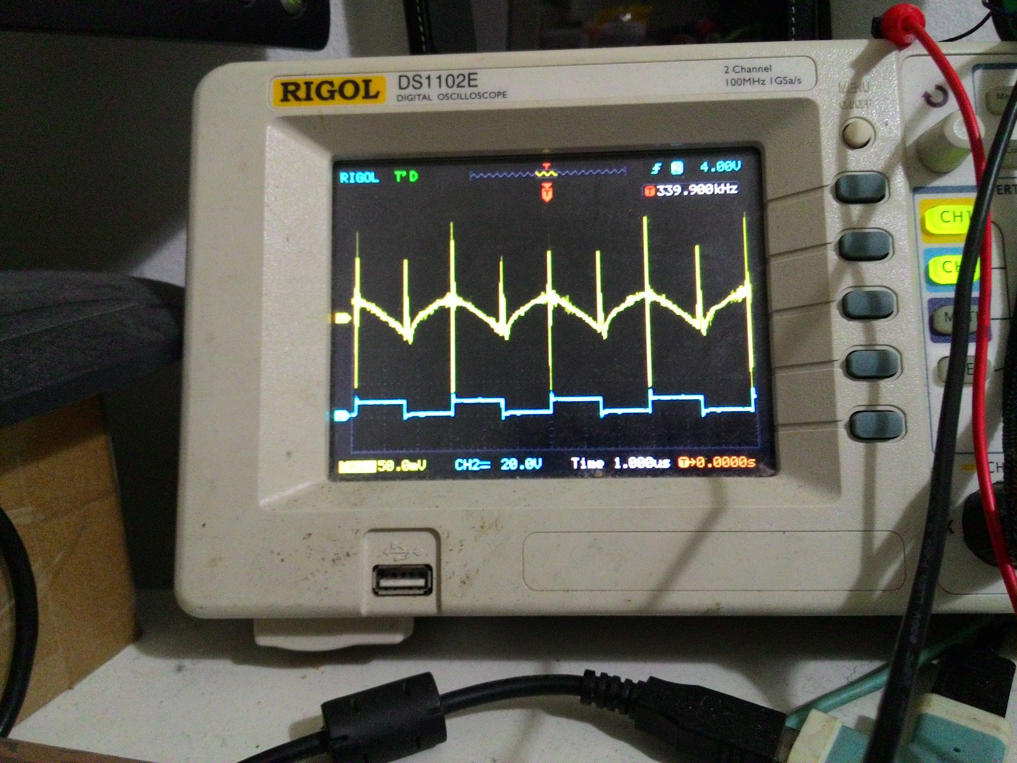
Image below shows ac-coupled supply rail (top yellow) and the half-bridge output (bottom blue).
As can be seen, the rail fluctuation is non-negligible and it will affect the opamp performance if left untreated.
The bridge output is stable at near 50% duty cycle, this indicates a good feedback loop.
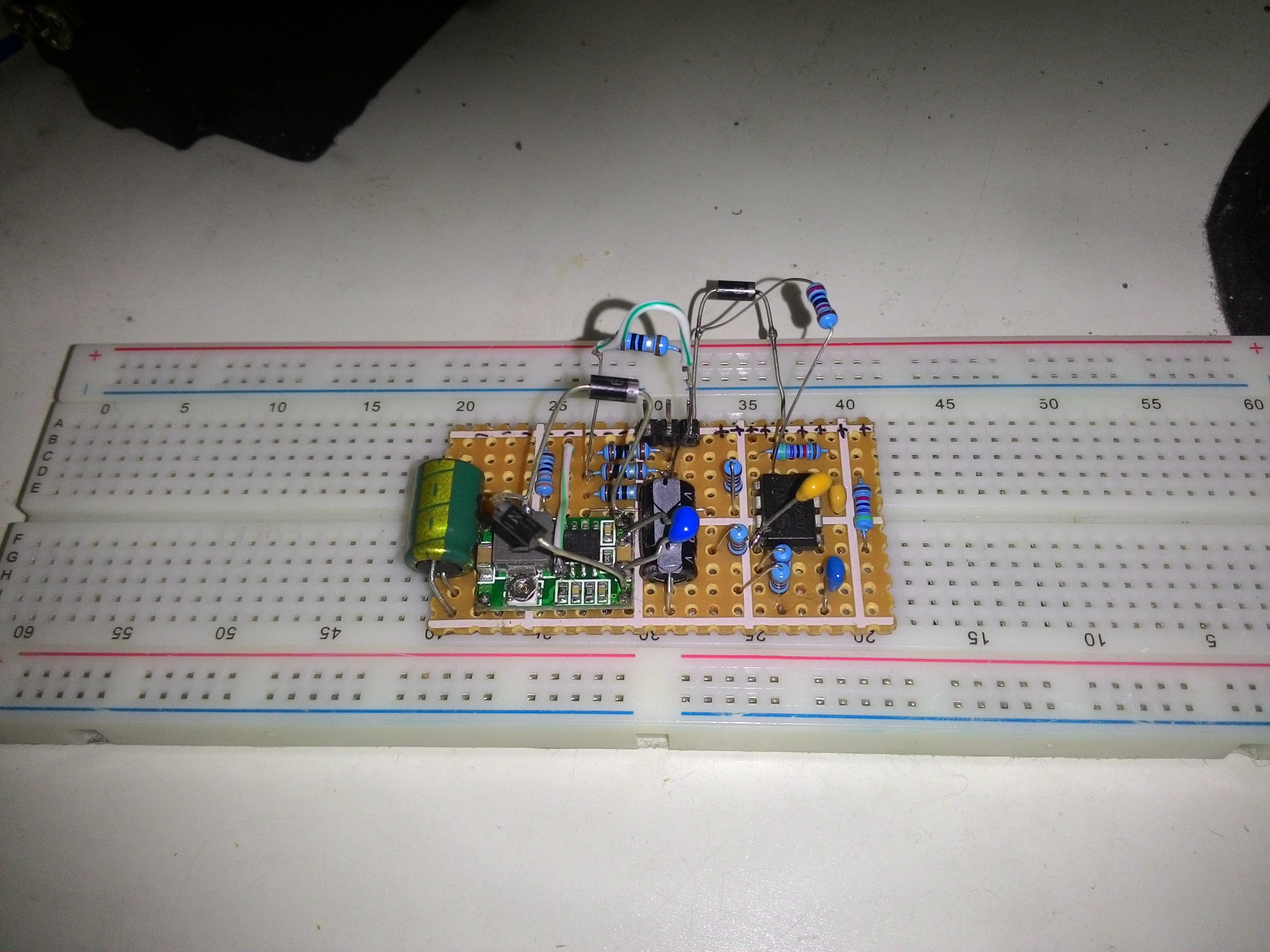
To improve the opamp's ripple rejection, I added a diode and a capacitor at the opamp's Vcc pin to isolate the noisy power rail from the opamp. I also added flyback diodes to suppress any possible ringing bemf.
I also added a direct current path (green wire) from the output to the battery balancing node. This allows faster balancing.
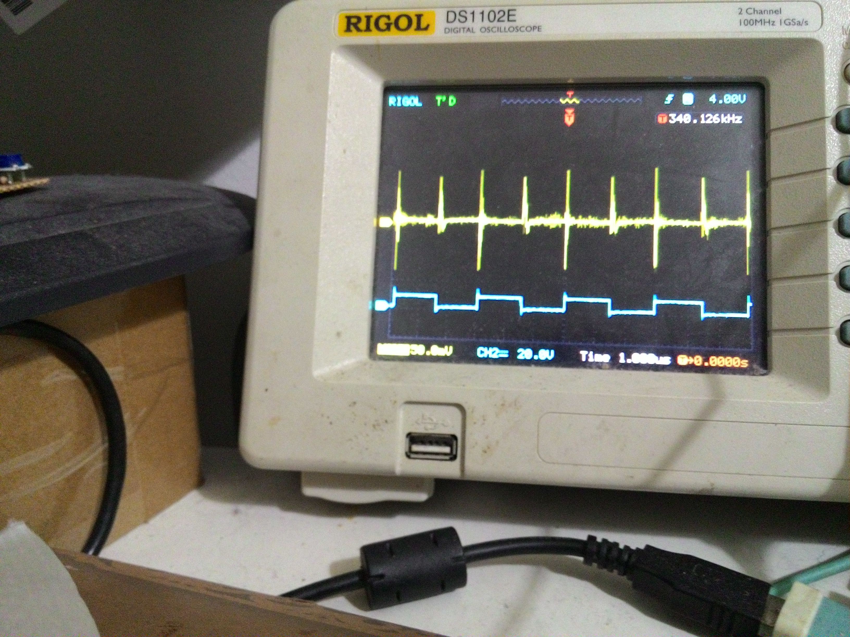
The result was a cleaner opamp supply rail with minimised ripple:
And also, a better negative-feedback signal:
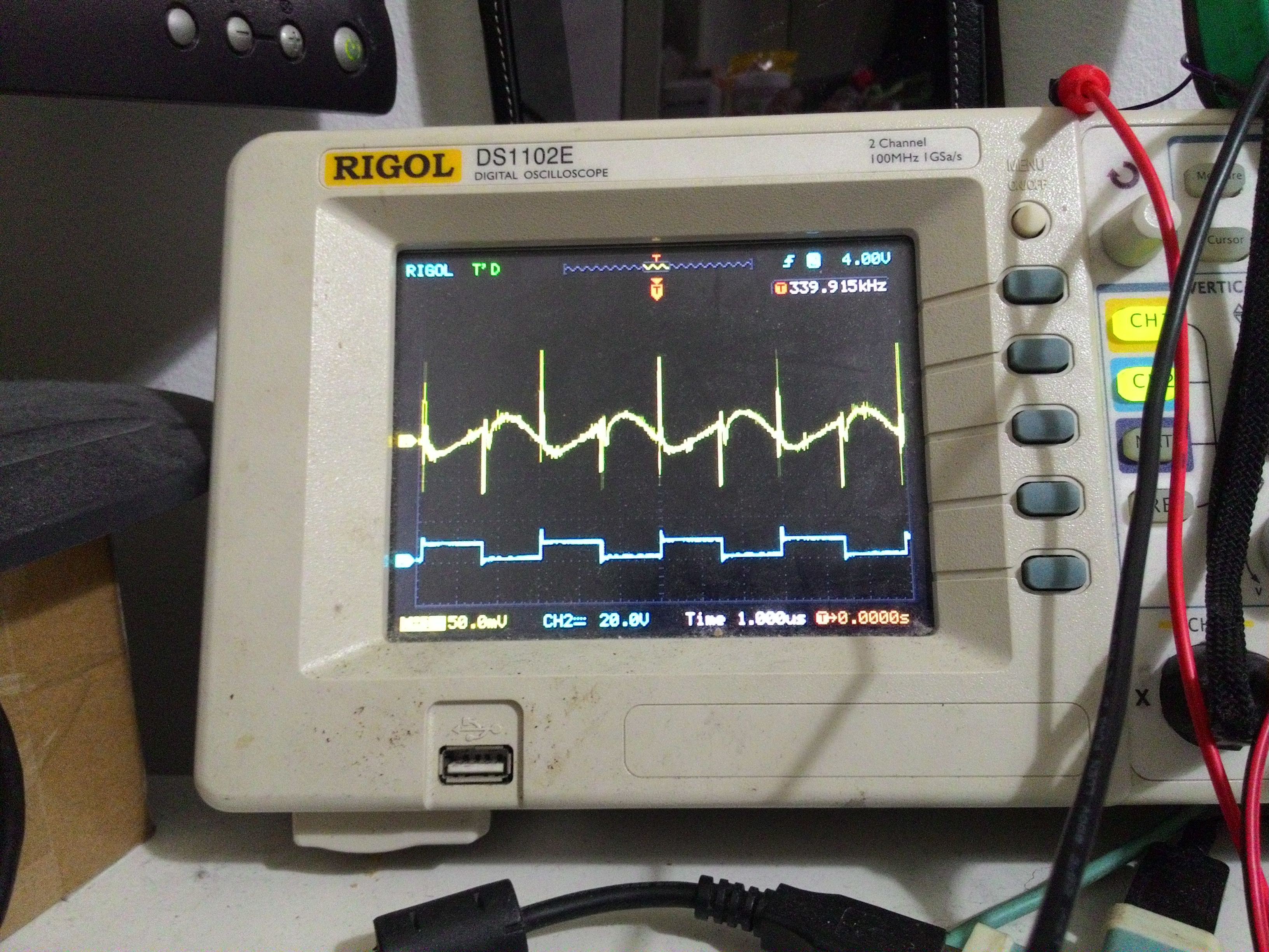
I am still struggling to remove the high-frequency component in the signal. Although the loop seems to be stable, I wanted to reduce it as much as possible to avoid EMI emissions.
I also tested the accuracy of balanced cells and it was measured to be around 4%, which is quite bad because of the sensitive nature of lithium battery chemistry.
Discussions
Become a Hackaday.io Member
Create an account to leave a comment. Already have an account? Log In.