Lots of Credit to Roman Black
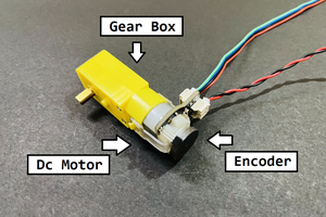
The program controls the position of a DC motor furnished with an optical rotary encoder. The position is determined by the position of a second rotary encoder.
The decoding of both the encoders is performed in a Timer0 Interrupt. TMR0 times out every 102.4uS. It captures the state of both encoders, compares with previous state and updates position information accordingly in two registers tpos and mpos (thumbwheel pos and motor pos)
tpos and mpos are then compared.
The difference is used to determine the PWM (CCP1 TMR2 set to 3125 Hz)
Direction control is determined. FWD if tpos > mpos & REV if mpos > tpos
The circuit is such that the PWM signal is fed to both sides of the H-Bridge
However, the impedance state of Pins REV and FWD determine if the PWM signal is available at the H-Bridge.
It works but feels like a kludge and could do with improvement.
Basically both Pins are set to outputs and driven low. This shunts the PWM feed to ground.
To make a direction active, the associated pin is set to input (high impedance) and therefore allows the PWM signal to drive the H-Bridge. Basically it is implementing a crude wire-anding.
*
Test results:
As the thumbwheel encoder is attached to one of the DC motors it made sense to supply a variable DC supply to drive the thumbwheel encoder for testing purposes rather than turn by hand.
The maximum applied voltage was 2.8V drawing 80mA. Beyond this point the system became unstable.
That is the encoder pulse ratio of Thumbwheel-Encoder: Motor-Encoder deviated from 1:1
The frequency of encoder pulses was measured at about 1200Hz.
As there are 36 slots on the encoder wheel, the rotation speed was calculated at approx 1200/36 = 33rps or 2000rpm
The revisit rate of TMR0 ISR is 102.4uS or 9765 Hz so the system should be able to cope with higher speed with some tweaks.
 justin.richards


 AVR
AVR
 ottoragam
 stdlogicvector
 Sagar 001
Code files have been added and tested. Also the schematic has been updated.