 Yann Guidon / YGDES
The last log 10. Electromechanical User Interface : the Assembler board raises an interesting and important question : how can I control the relay-based computer with something like a Raspberry Pi ?
I'd like to control and spy on the machine with a modern computer, replace the DRAM and the PROM with user-controlled modules that emulate them with SRAM, write or read registers, see the result of instructions, upload and save programs...
I need to interface hundreds of signals from a 3-6-12-24V system (requiring 60mA drive currents) with the meek 3.3V CMOS GPIOs of today's generation.
The last log implied that the instruction bus would "switch the high side". I already have the signal distribution paths figured out but I didn't think too much about the most favorable direction of the data signals. I just assumed the sense coils to be wired to 0V and the data coming from +Vcc. Simple.
(diagram)
Then the building of the Assembler board made me reconsider my assumptions because I would like to "upgrade" the board to add a shift register that takes over the switches.
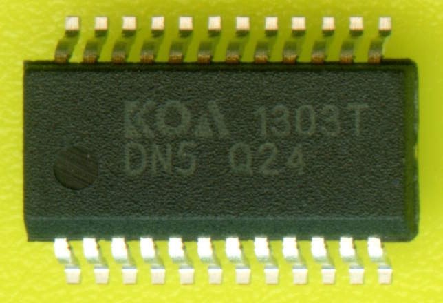
All the practical electronic/IC solutions I could find are referenced to GND and "switch the low side". The sense relays require some significant current (60mA without prebias). In particular, this part is very well suited to the task:

This obsolete chip is a 16-channel constant-current sink LED driver in 24-pin DIP. It runs up to 20MHz with 3V-5.5V logic supply but can sink up to 80mA per channel (20V maximum on the pins). I need 1 and half to drive the instruction sense relays... From the lower side.
I have already wired the diodes of the switches for high-side, I can change them. But the ROM and PROM boards already have some parts in stock, that are meant for high-side switching !
The solution comes again from exdwh's store !

The even funnier thing is that you can configure it however you want, with low side or high side: just connect the appropriate common rail to the proper voltage. The circuit is also (almost) symmetrical so a single footprint/PCB can accomodate both uses, just solder the package in the appropriate direction ! (ooooops I realise now it's a miroring and not a rotational symmetry)
The leakage is too high and the voltage rating too low to help with DRAM. But if the voltage is kept low enough (less than 7V) this is totally suitable for the PROM boards, as the current is just enough and the spikes shouldn't last long enough to damage the diodes.
Now, I must find a way to increase the sense coils' sensitivity...
The current and voltage can be reduced with a switched capacitor cell which is almost the same circuit as the typical latch.
- The hysteresis is held by 2 coils in series, so there is one output for the datapath control lines, and one for the disassembly board.
- The middle point is tripped by a capacitor, switched by another relay. Just like the latch circuit.
- The other side of the relay is held high by a pull-up to 6V. Value: t=RC, R=t/C, the charge is held in a 100µF capacitor (like most others). It must be charged in 20ms, which gives about 500 ohms. Rounding up to 600 Ohms gives 10mA when shorted to 0V, instead of the 60mA we wanted initially... the added diodes will reduce the current a bit more.
- To increase sensitivity, the sense middle point is held at 3.3V by 2 resistors (on the 0V and 6V rails). In parallel with the resistors, capacitors stabilise the relays...
- The input is held high by the pull-up, but overriden by the low-side switches (either solder blots, switches, N-channel FETs....)
The sense coils become "instruction register" (using no less than 3 caps, 3 relays, 3 resistors).
(diagram)
This is interesting because the capacitor switching can be controlled by the same clock as the register set (when enabled). This creates some pipelining, which makes scheduling more interesting... there is a fetch during exectution.
Very interesting.
Discussions
Become a Hackaday.io Member
Create an account to leave a comment. Already have an account? Log In.
"SPI high side driver" is probably what you'll need. SPI is high bandwidth enough for the high I/O, and yet few enough pins that reduces the number of level shifting. Also consider running the relays at negative supplies if you want to avoid level shifting the SPI. This also let you use NMOS. I built a VFD driver that way using CPLD for large I/O count.
I was laying out a discrete one with HC595, 8 SOT23 PMOS and passive pull down on a SIP, but lost motivation.
Are you sure? yes | no
I wanted to reduce the parts count, and I hadn't planned for the external digital control from the beginning, it came a bit late in the game... I didn't want to solder 24+ discrete transistors and cram them like crazy. An integrated circuit made more sense.
For the negative voltage, well that's an idea worth considering, thanks ! however it might just confuse me even more as I have the voltage scheme in my head already with 0-3.3-6.6-12V and changing this increases the risks of errors.
So I just inverted the current flow on the instruction bus.
I need to sketch more diagrams and write more logs...
Are you sure? yes | no
If you are using proper high side driver chips with built-in level shifting, then It is kind of moot to consider negative rails.
Are you sure? yes | no
I haven't found high side drivers. I have a few MOSFET drivers but they are one or two outputs per 8-pins chips, so I'd need 12 or 24 of them.
I have PMOS but no suitable IC with open collector output (only global output enable).
The STP16DP05 is a convenient solution that I have adopted. I don't know PMOS versions of this, and now it's pointless anyway :-)
Are you sure? yes | no
google for high+side+driver+SPI Just on page 1 alone:
http://www.st.com/en/automotive-analog-and-power/l9733.html
https://www.onsemi.com/pub/Collateral/NCV7608-D.PDF
http://www.infineon.com/cms/en/product/power/smart-low-side-and-high-side-switches/multichannel-spi-driver-enhanced-relay-control-spider/channel.html?channel=ff80808112ab681d0112ab69dfb9034d
http://www.nxp.com/products/automotive-products/energy-power-management/engine-and-dc-motor-control/h-bridges/octal-serial-switch-with-spi:MC33880
http://www.allegromicro.com/en/Products/Motor-Driver-And-Interface-ICs/High-and-Low-Side-Drivers.aspx
https://datasheets.maximintegrated.com/en/ds/MAX14900E.pdf
Are you sure? yes | no
BTW 20 MOSFET. :P
https://cdn.hackaday.io/images/4757101492398828283.jpg
Are you sure? yes | no
Very interesting.
Are you sure? yes | no