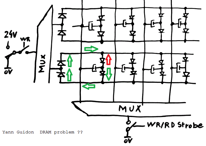
@roelh was suspicious that my "new DRAM array" would work.

It took him a while and conviction, and it was difficult to wrap my head around it.
I'm too lazy to finish the prototype, but it would be useless for 2 reasons :
- Probing the capacitors would disturb the array and storage
- I don't have enough channels to observe a 16×16 array !
So I resorted to simulation.
Spoiler alert : @roelh was right. But why ?
After I did the experiments, I realised that I was influenced by the flipdot array and impressed that it could drive several rows at the same time. Using the re-steering diodes makes sense.
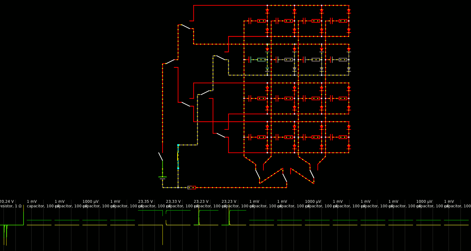
But the rows are always driven so the current "loop" that roelh identified don't occur. In my case however I leave many rows undriven. And the simulation shows really bad consequences.
In practice...
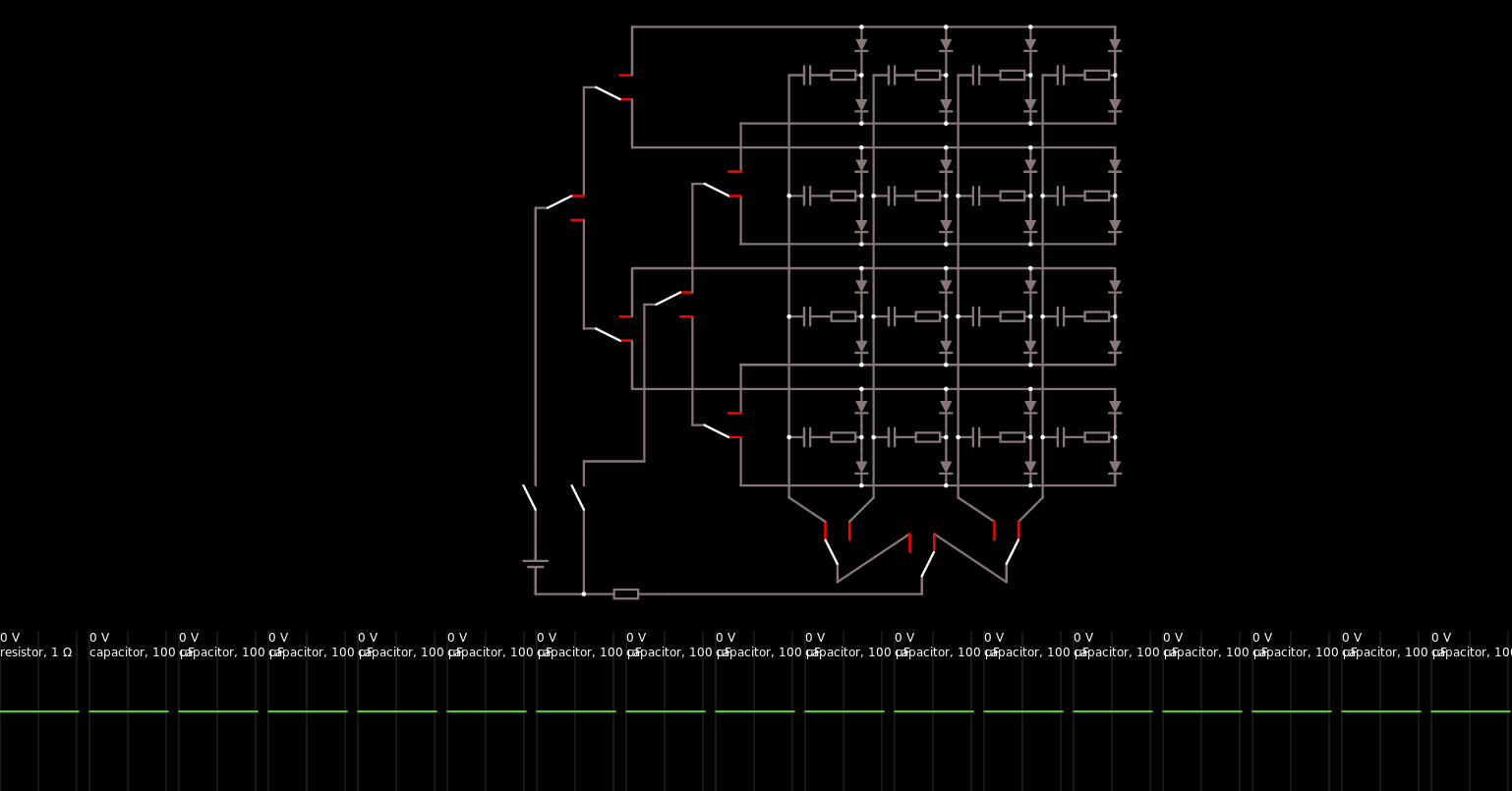
Just go to http://www.falstad.com/circuit/circuitjs.html and "import from local file" the circuit that I have uploaded.

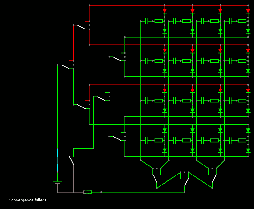
Click on the push buttons and the SPDT switches to steer the current. You'll see the capacitors' charges vary. I added a bit of ESR to reduce the pulses. Be ready for some ... lag. The simulator gets confused after a few manipulations and I have already encountered errors...

I have "probed" all the capacitors (with virtual scopes) to check that charging one doesn't influence the others.

I have chosen a topology of double binary tree because I don't want the data to have too much fanout. Using the recent tree command topologies, the double tree is actually practical and has a fairly balanced fan-in.
Conclusion : I must reorganise the DRAM geometry.
The double-tree that selects the row is a big burden which shouldn't increase so I consider reducing the rows to only 8 per bitplane. In parallel, there are 18 bitplanes with 8 rows each, which amounts to 18×14=252 relays.
As a consequence, the backplane must handle more columns : 512/8=64 columns, or 64 relays. It must withstand the simultaneous switching current of 18×100µF so I consider using a small series resistor to mitigate the transients.
I think about building DRAM modules made of 8 rows and 16 columns.
 Yann Guidon / YGDES
Discussions
Become a Hackaday.io Member
Create an account to leave a comment. Already have an account? Log In.
But you still need the diodes? My DRAM works without diodes. So it seems. I do not understand what the diodes are doing.
Are you sure? yes | no
The best I can say is : run the simulation :-)
What are your parameters ? dimensions, capacitance, number of read/writes between refresh...
Are you sure? yes | no