Audrey Robinel
-
About sensors
03/15/2016 at 02:11 • 0 commentsI used DHT22 sensors for a while. I'll continue to use it in some project, and i'll keep supporting those for this project, because they're cheap and easy to come by. However, those are not really good sensors. Why? Because of their weird communication protocol, low accuracy, and variance between multiple sensors. They are good enough to know if it's hot, wet, etc, but not so much to measure those parameters.
![MCP9808]() We're trying to build a meteorological station/network of sensors here, so let's up the standards. I have bought an MCP9808 from Adafruit, that is given to have a good precision, and a guaranteed 0.5 max error at common temps. It's also I2C, a standard and and widespread protocol. For 5$ it should be more reliable than what we get from the DHT22/DHT11, and we'll see how it compares to the DS18B20.
We're trying to build a meteorological station/network of sensors here, so let's up the standards. I have bought an MCP9808 from Adafruit, that is given to have a good precision, and a guaranteed 0.5 max error at common temps. It's also I2C, a standard and and widespread protocol. For 5$ it should be more reliable than what we get from the DHT22/DHT11, and we'll see how it compares to the DS18B20.![BME280]()
I also ordered a BME280 from Adafruit for 20$, and it is supposed to be much more accurate about temperature, pressure and hydrometry. I also ordered this version of the BME280 from Aliexpress for 7$. When i get all those sensors, i'll make a measurement box with data logging and compare the results of all sensors (including the DHT11, DHT22, DS18B20, etc).
That's for the basic sensors. I don't have a way to compare loads of anemometers, rain meters, or wind direction sensors. I'll use what i have, and what can be easily found : the sparkfun kit.
I decided to make this more of a environnemental measurement station than just a meteorological station, meaning that we won't restrict ourselves to classic sensors.
I will measure the amount of dust in the air, using a cheap sensor with the GP2Y1010AU0F, that i bought from aliexpress at 8$ for a 2-pack. Again, i have nothing to compare those to, but at least i can check for consistency over time and among multiple sensors.
I also plan to include lux sensors, UV radiation sensors, and even a radioactivity sensor.
So, we'll make everything possible to support the most common sensors, but also try to use higher quality sensors if available.
-
Adding interrupt routines for the interface
11/20/2014 at 02:21 • 0 commentsAs of today, i had a little box showing some parameters. After some time, it would show another parameter on the second line. However, what if i wanted to check another parameter when i want?
For that, i need to have a button to change what is shown on the LCD. The problem is that reading the sensors is made in a blocking way, meaning that i can't just poll the button state, because i will often miss the presses. A solution to this problem would be to modify the libraries so that it becomes non-blocking, but i don't feel like doing so. Another solution is to use interrupts.
Indeed, Atmega chips can handle multiple interrupts, and i can have a function executed whenever a pin status change occurs. Nick Gammon wrote a nice tutoriel about it here. Using this trick, i was able to capture the button presses.
In interrupts, delay() is disabled, as it relies on interrupts too. You can enable interrupts within interrupts, but it can be complicated. So to debounce the button, i have declared a variable as "volatile long" to store the last button press time (obtained with "millis()"). If enough time has passed since the last button press, my function does something, otherwise nothing happens.
When a good button press is recorded, i reverse the value of a volatile int variable, and end my function there.
In the loop function, a parameter or another is printed, depending on the value of the int variable.
Variable used by an interrupt must be declared as "volatile", so that the chip loads the variable value each time it uses it, instead of using the previously loaded value. As the interrupt can alter those variables any time, i ensures that the latest value is used.
Thanks to interrupts, one can design an user interface for a project , whatever the chip is programmed to do. It is possible to check any pin in the interrupts.
I will later include github links to the code for this example.
-
Luminosity - lux sensor
08/27/2014 at 01:18 • 0 commentsI have recieved my order from Sparkfun. Among the stuff i ordered was a luminosity sensor, the TLS2561. Sparkfun made a great tutorial for it. Rather than soldering pins to plug it to a breadboard, i soldered female jumper wires. Since this sensor has to be exposed to light, a little lenght of wire will make it much more simple.
This sensor works on I2C, and is easy to use, thanks to the provided library.
Depending on the conditions, you can set a gain, and exposition time, so that it can be used in low light condition as well as in bright light.
I have tested it indoor, but i lack another lux sensor to compare the accuracy. However, it will do for now to obtain an idea of the sun level. I have been able to measure 1 lux up to aproximately 60 000 lux.
I plan on screwing the breakout board on a little support, and add some transparant material in front so that i can measure outdoor luminosity without fear of rain or moisture.
-
new temperature sensor
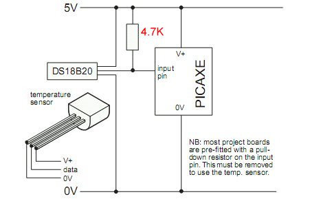
08/23/2014 at 04:16 • 0 commentsToday i added a much better temperature sensor : a DS18B20. It is really simple to interface : the left wire goes to the ground, the middle wire goes to the GPIO and to VCC via a 4.7K resistor, and the left wire goes to VCC. This disposition is for when you look at the flat side of the probe, with the leads on the bottom.
![]()
Of course, in my case, the data pin goes into a Atmega328p rather than a picaxe.
Software side is a bit more complex, hopefully, there are libraries available :
http://www.pjrc.com/teensy/td_libs_OneWire.html
From there i use a function to read the temperature (can't remember where i found it) :
float getAirTemp()
{
//returns the temperature from one DS18S20 in DEG Celsius
byte data[12];
byte addr[8];
if ( !ds.search(addr)) {
//no more sensors on chain, reset search
ds.reset_search();
return -1000;
}
if ( OneWire::crc8( addr, 7) != addr[7]) {
Serial.println("CRC is not valid!");
return -1000;
}
if ( addr[0] != 0x10 && addr[0] != 0x28) {
Serial.print("Device is not recognized");
return -1000;
}
ds.reset();
ds.select(addr);
ds.write(0x44,1); // start conversion, with parasite power on at the end
byte present = ds.reset();
ds.select(addr);
ds.write(0xBE); // Read Scratchpad
for (int i = 0; i < 9; i++) { // we need 9 bytes
data[i] = ds.read();
}
ds.reset_search();
byte MSB = data[1];
byte LSB = data[0];
float tempRead = ((MSB << 8) | LSB); //using two's compliment
float TemperatureSum = tempRead / 16;
return TemperatureSum;
}
From there, i can read the temperature using this function.
The temperatures that i get from this probe are a lot more accurate than those of the DS18B20, or the BMP085. Furthermore, i now have tenths of degrees rather than full degrees steps.
-
Battery power
08/20/2014 at 06:46 • 0 commentsThis first module is not intended to be the "main" module. I will thus probably modify it later on to put it in remote locations. However, as of now, i want to be able to take it wherever i need it, in order to obtain measurements in various places. Hence the need for a battery. I added a 2000mAh LiPo battery (1S, 3.7V), and a "S7V7F5", a 5V pololu switching regulator (step-up and step-down : http://www.pololu.com/product/2119). I like it because it is able to boost the voltage as well as lower it, and has around 80-90% efficiency. It is also straightforward to use, as it can be used in the same fashion of a LM7805.
With the LCD on, and a fully charged battery, i achieved between one an two days of autonomy. I will later measure the current accurately to perform precise estimations of what to expect.
In order to charge it, i'm using a simple circuit from adafruit : https://www.adafruit.com/products/1304 , an "Adafruit Micro Lipo - USB LiIon/LiPoly charger".
I splitted the wires from the battery leads, and thus i can have it plugged while charging. According to adafruit's tech support, it can be done : https://forums.adafruit.com/viewtopic.php?f=22&t=58376
I tested it, and it works.
I thus have a USB or battery powered device.
![]()
I will have to conduct further experiments on battery life, without the LCD backlight, and probably with a 3.3V VCC rather than 5V. Indeed, this drastically reduces the current needed by the atmega.
I may use a solar panel later on to keep the battery charged.
-
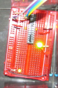
Adding an interface
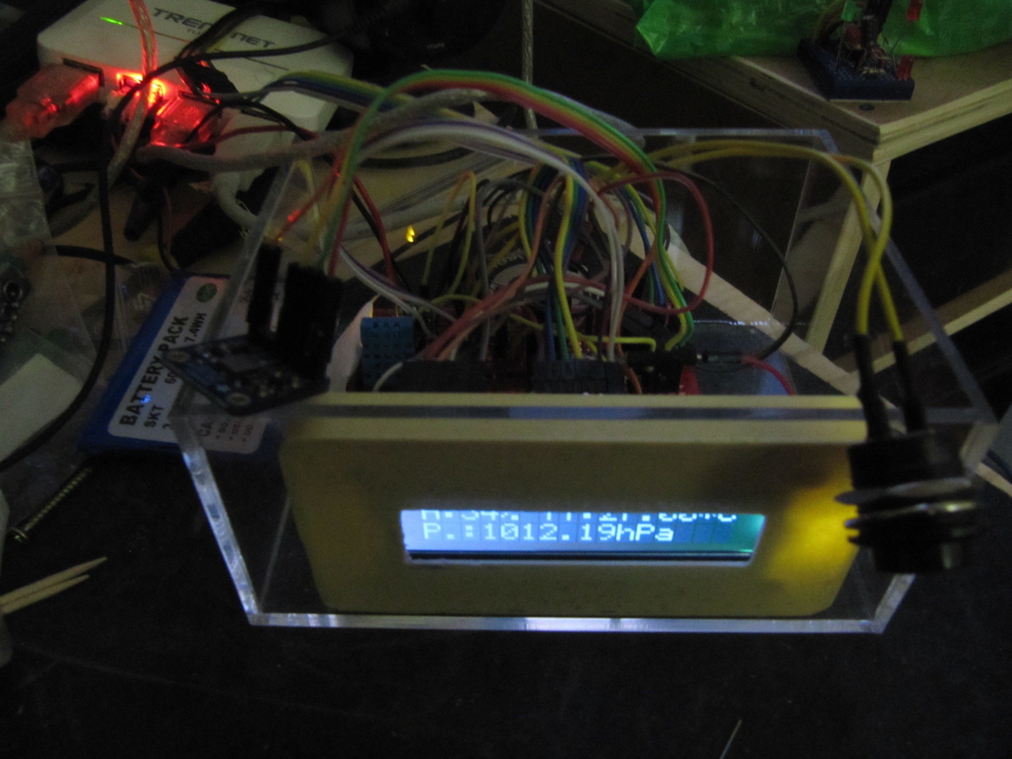
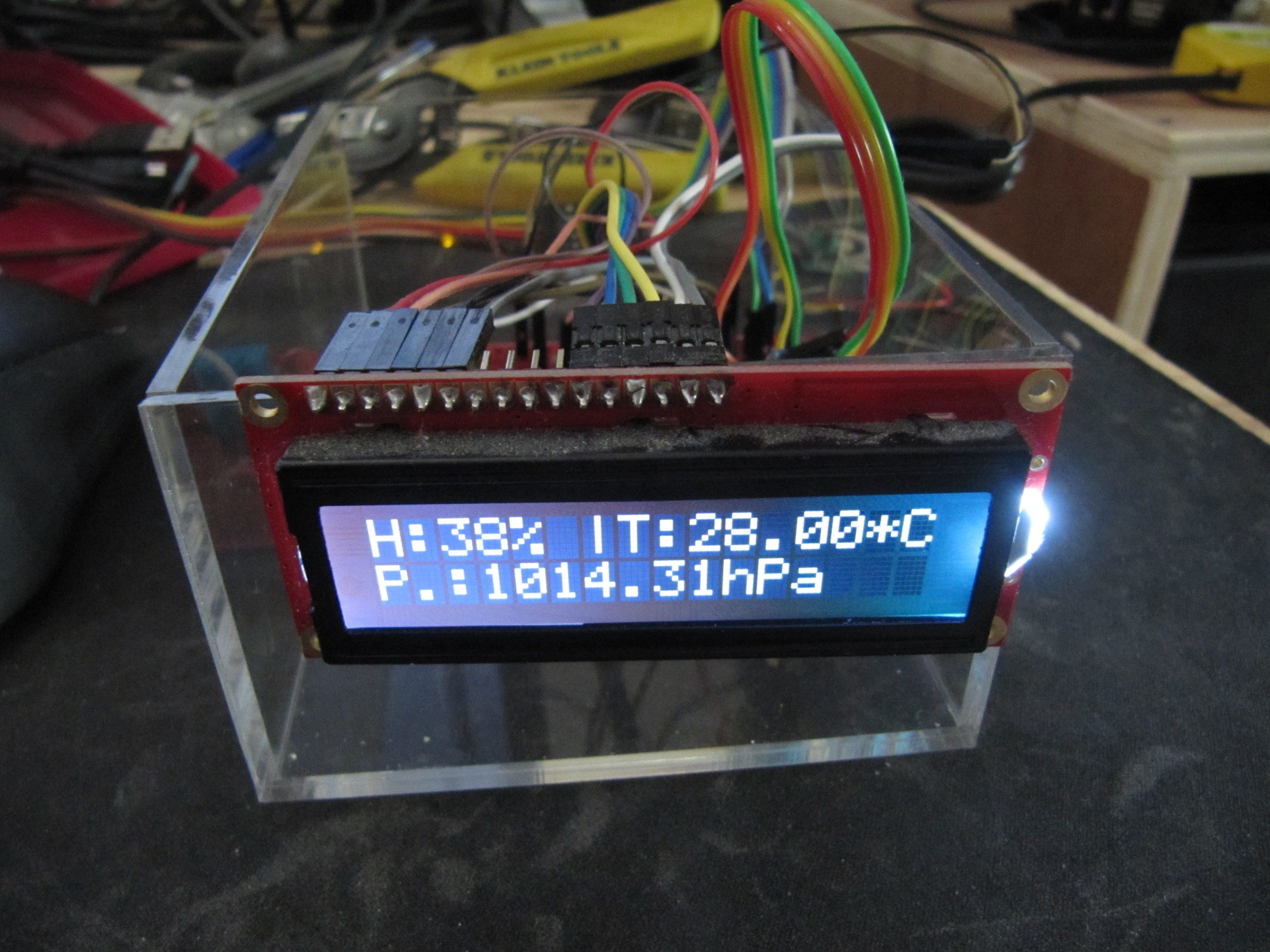
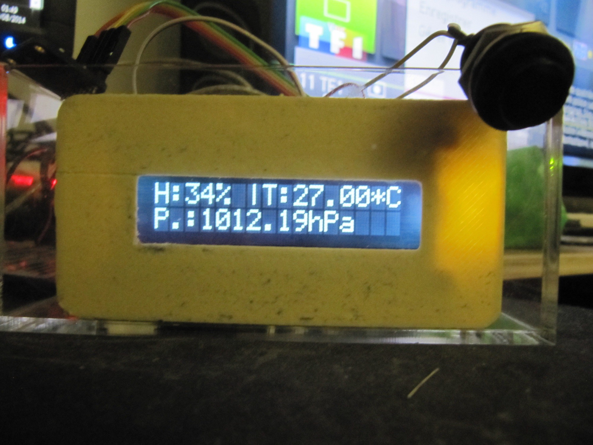
08/20/2014 at 06:31 • 0 commentsIn order to visualize the measurements, i included an LCD screen. I had a few laying around, so i picked a 2*16 char lcd with white backlight. This one has a pretty good contrast, and can easily be read outdoor, even under the sun.
On the first light, i print the humidity and temperature, and on the second line is the atmospheric pressure and the luminosity.
I also did 3D print a bezel for the LCD, found on thingiverse. I will probably design my own later on.
![]()
![]()
I also added a button in order to issue commands to the system, but it doesn't work as of now, for a simple reason : i am using a DHT11 library that is blocking when reading. Indeed, with this library, if i ask a read, it does wait for aproximately 1000ms, before continuing. I thus spend most of the time waiting, rather than reading my button state. I will have to either find a non-blocking version of this, or later modify this library for non blocking readings.
-
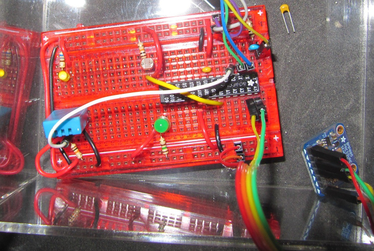
First sensors
08/20/2014 at 06:22 • 0 commentsThe first module measures a few parameters : temperature, humidity, atmospheric pressure, and luminosity.
Temperature and humidity measurements are provided by a DHT11 sensor. However, i'm using the DHT11 mainly for humidity, as the temperature measurement are not really accurate. Temperature measurements will be handled by a DS18B20 later, as i found those to be more accurate and reliable.
Atmoshperic pressure measurements are provided by an adafruit BMP085 module (https://www.adafruit.com/products/391). This sensor is now discontinuated, and can be replaced by the BMP180 (https://www.adafruit.com/products/1603) with the same code, wirering, etc.
The light level measurements are provided by a light dependent resistor. However, i used this because i had a few, and had ADC pins left. Indeed, those sensors are not very accurate, and i don't really see how to translate the measurements in lux. Those can however be useful in order to detect if it is dark or not.
![]()
-
First module : the processor
08/20/2014 at 06:10 • 0 commentsEvery project has to start somewhere. So here, the start is rolling a atmega on breadboard. I am using an ATmega328p, with optiboot. It is set to run an 8Mhz, using the internal crystal, because i don't need more power, and i want to reduce the parts count.
So for this, i have an Atmega328p, 3x 100nF capacitors, a 4.7KOhm resistor, a breadboard, and some wire. I program it with an USB to serial bridge, using Arduino sowftware.
![]()
The main chip unit is not really important here, i used an Atmega because i had a few available, but later on it could be replaced with an ATtiny. I will stay with Atmel chips, because i know how to program those, it is easy to use and powerful, and also the fact that the code can be used easily by other people, be it with a small Attiny, or a full Arduino Uno, Mega or whatever.
Milapli
An open source/hardware meteo station, also monitoring other environemental parameters