-
1Step 1
Ripping Everthing Apart!
This is the fun part.
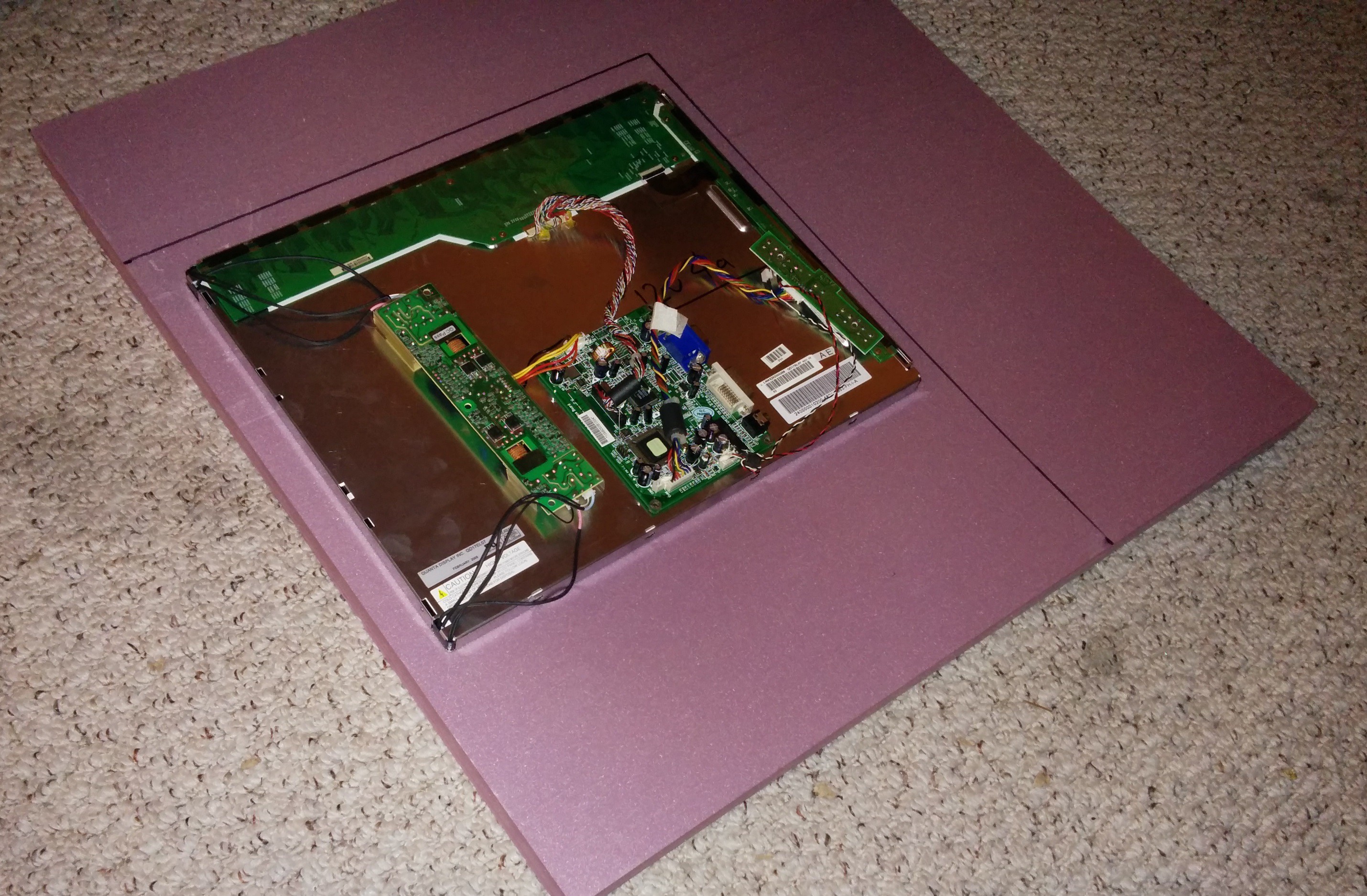
Find yourself an old LCD Monitor.. Thrift Shops are great for this.
I got my LCD Monitor used in the arcade for $8!
I took everything apart on it, to save space, weight, and because I was mounting it into a seperate housing. Be careful when taking the monitor apart, there are a lot of flimsy wires that take finesse to wiggle out of place.
![]()
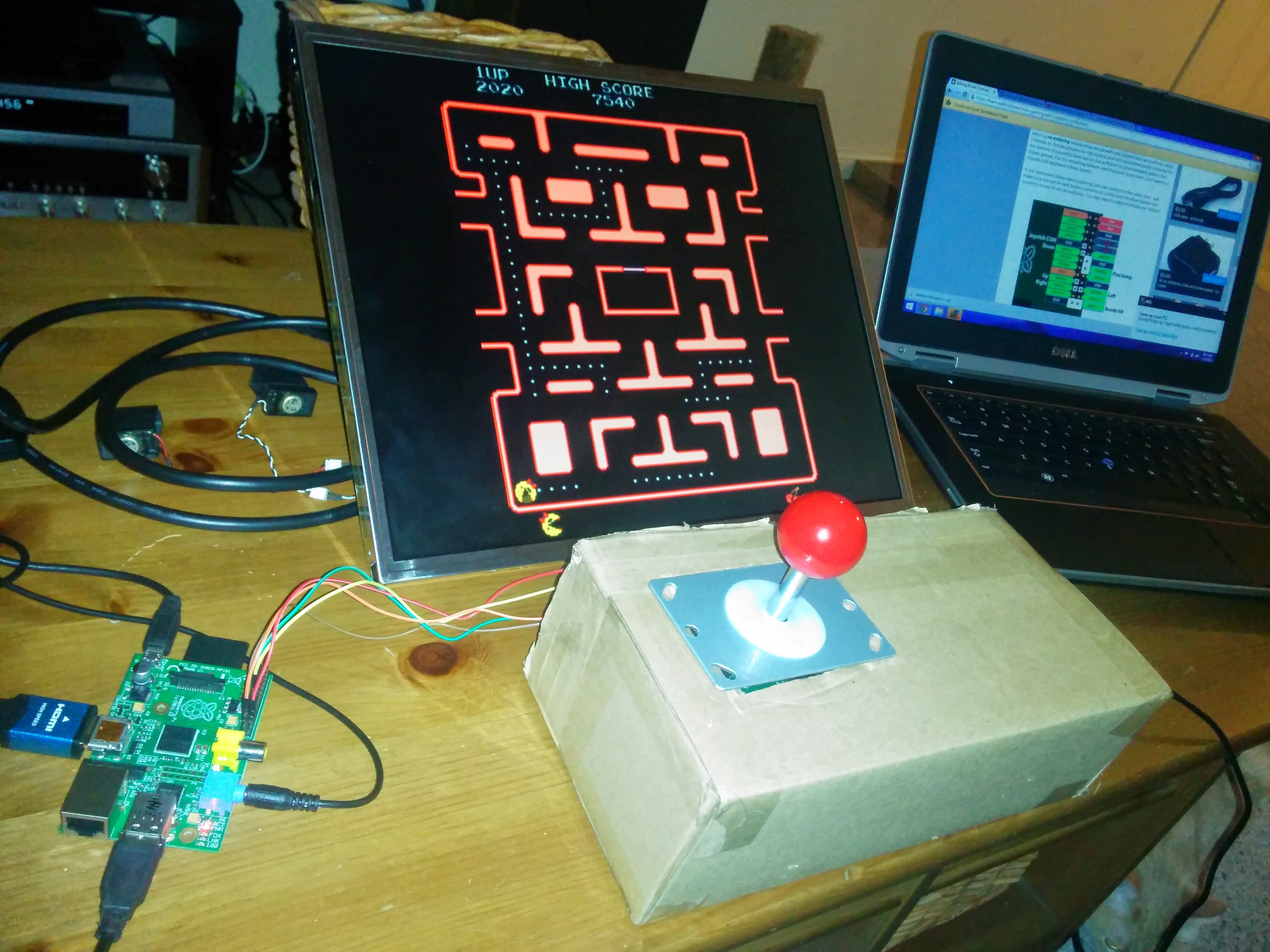
Now that you have a nice terminator style monitor, you can plug it into your Raspberry Pi!
Also on the list of things to tear apart:
Speakers: To mount into your arcade cabinet. (Keep the speaker grills! They make great touches to the final product. If you went with the Logitech Z100 Speakers, here is a great video of a teardown.
Computer Fan: Find an old desktop laying around in your garage and cannibalize every fan you can... if not, buy it on Amazon, or Bestbuy.
-
2Step 2
Wiring the Joystick and Buttons (Optional Soft Mount)
![]()
This will be the start of your amazing Raspberry Pi Arcade System!
First, you must become familiar with the Raspberry Pi GPIO.
![]()
This will be where you plug in all the buttons and joysticks.
The awesome folks at Adafruit have compiled a very detailed walkthrough and library to glue the hardware and software together to get your buttons and joysticks running.
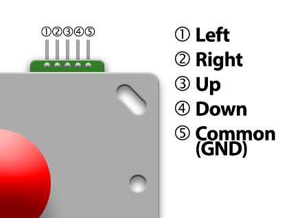
First, take a look at your joystick.
With the pins facing up, this will be the orientation of the joystick.
![]()
Using your Female to Female jumper wires, connect each pin to a corresponding GPIO Pin.
The following is an example of how you can wire your joystick/buttons.
![]()
![]()
If you followed that layout, the next step of the process is quite simple.
Download retrogame from GitHub. Select the “download ZIP” button and uncompress this file on your Raspberry Pi. /home/pi directory.
A pre-built version of retrogame is included in the ZIP file. If using the joystick and button layout described above, this program can be used as-is. Otherwise, the C source code needs some editing, and you’ll need to compile it (a Makefile is provided) after making changes. The GPIO pin to keyboard remapping is currently handled with a table in the source…this should be edited to match your unique wiring setup.
open your terminal and type the following.
cd Adafruit-Retrogamenano retrogame.c
nano retrogame.c
(Of course you can substitute your editor of preference there — “nano” is easier for beginners.)
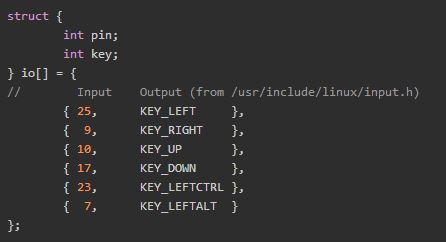
Starting around line 77 you’ll see a table resembling this:![]()
Each line in this table contains two elements. The first is a GPIO pin number (where a button or one direction from a joystick is attached), the second is the corresponding key code to be generated by this control. A list of valid key code names can be found in the file /usr/include/linux/input.h starting around line 178. Remember to enclose each pin/key pair in {curly braces} with a comma between them.
By default, the code is set up to match our example “no solder” controller wiring. This also works directly with the standard MAME controls. So you might not need to change anything; the pre-built version may have you covered.
If you need an extra ground pin (and have extra GPIO pins available that you’re not using for controls), set the key code to GND instead.
Write your changes to the file and exit the editor, then type:make
This should build the executable retrogame utility. If you instead get an error message, there’s a problem in the edited table — most likely a missing curly brace, comma or semicolon.
But wait…we’re not ready to run yet! Retrogame requires the uinput kernel module. This is already present on the system but isn’t enabled by default. For testing, you can type:sudo modprobe uinput
To make this persistent between reboots, append a line to /etc/modules:
sudo sh -c 'echo uinput >> /etc/modules'
Now we’re in good shape to test it!
Retrogame needs to be run as root, i.e.:sudo ./retrogame
Give it a try. If it seems to be working, press control+C to stop the program and we’ll then set up the system to launch this automatically in the background at startup.
sudo nano /etc/rc.local
Before the final “exit 0” line, insert this line:
/home/pi/Adafruit-Retrogame/retrogame &
If you placed the software in a different location, this line should be changed accordingly. “sudo” isn’t necessary here because the rc.local script is already run as root.
Reboot the system to test the startup function:sudo reboot
The software will now be patiently waiting in the background, ready for use with any emulators.
Each emulator will have its own method for configuring keyboard input. Set them up so the keys match your controller outputs. Up/down/left/right from the arrow keys is a pretty common default among these programs, but the rest will usually require some tweaking.Congratulations, you have just successfully wired hardware to your Raspberry Pi and glued it together with a little C Code! Go you!
I got stuck at this stage of the process because I couldn't stop playing the games!
KEEP CALM AND TINKER ON.
-
3Step 3
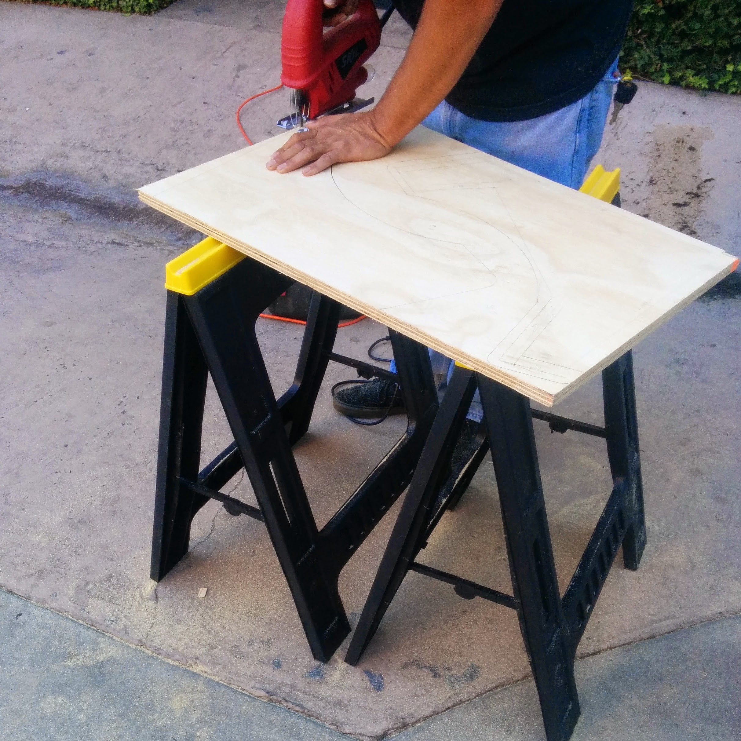
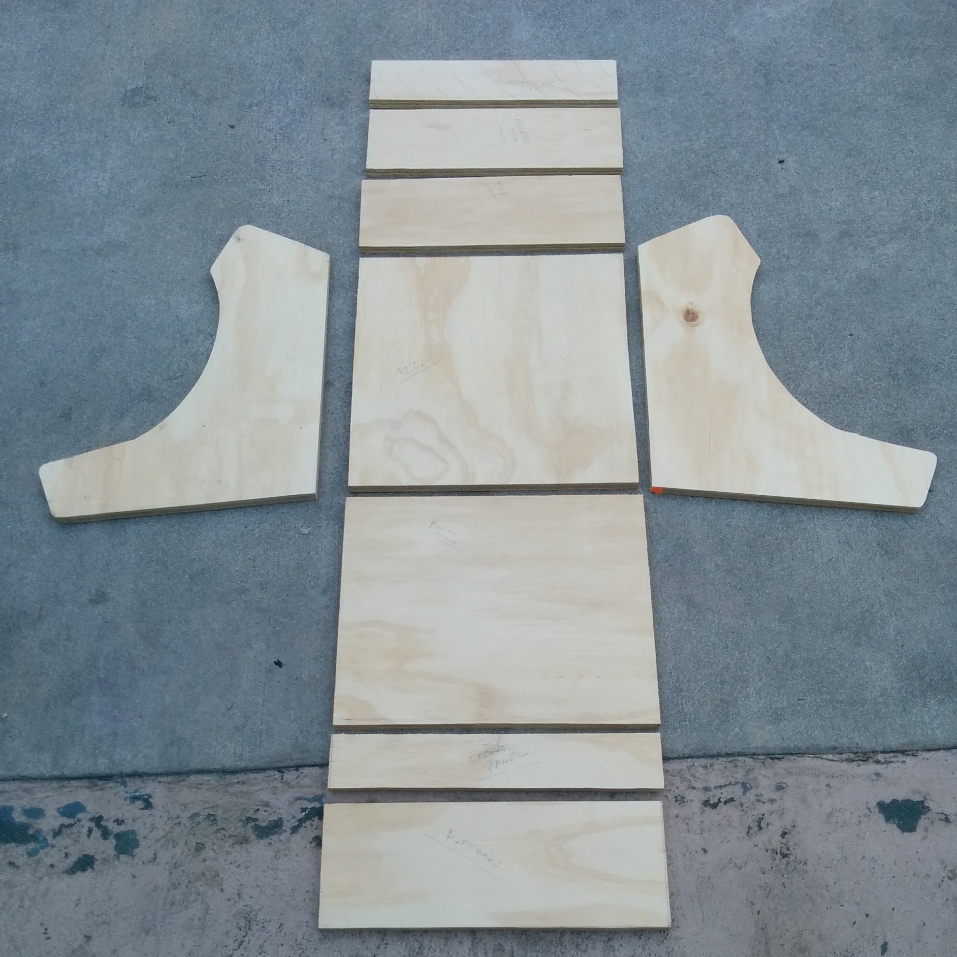
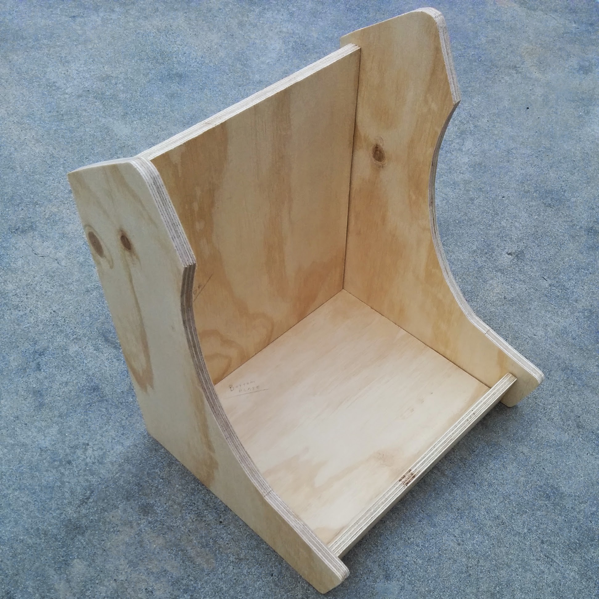
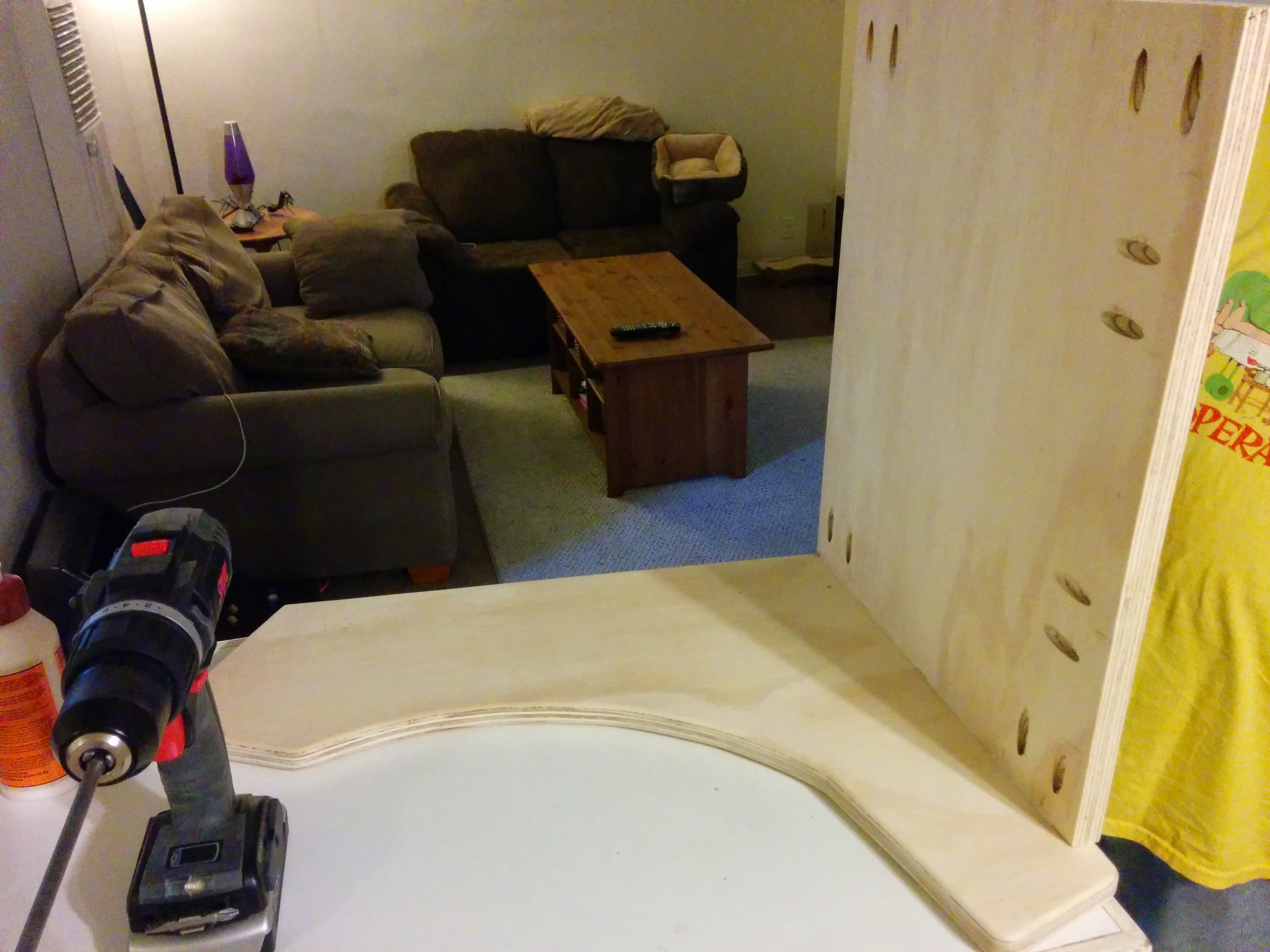
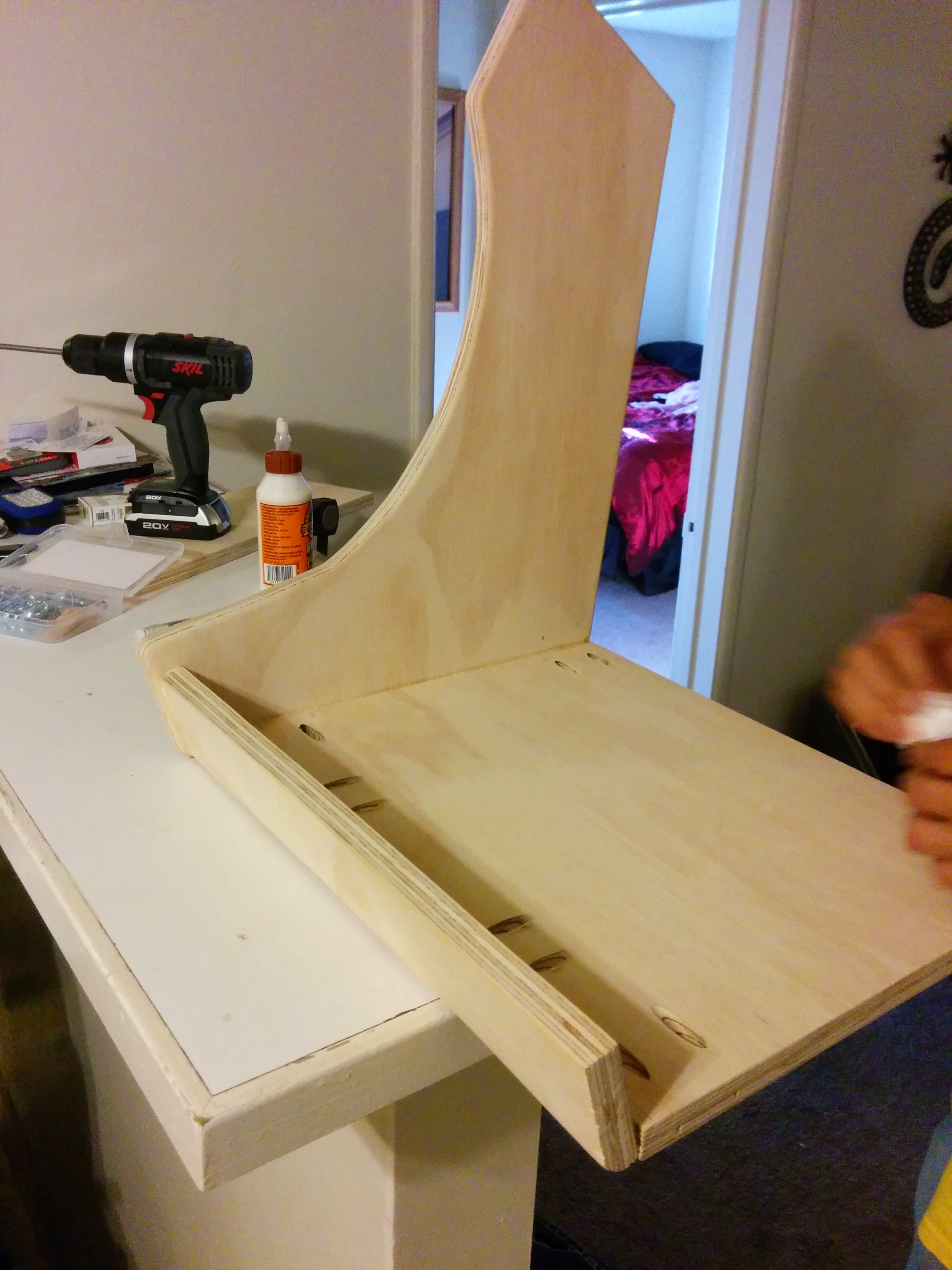
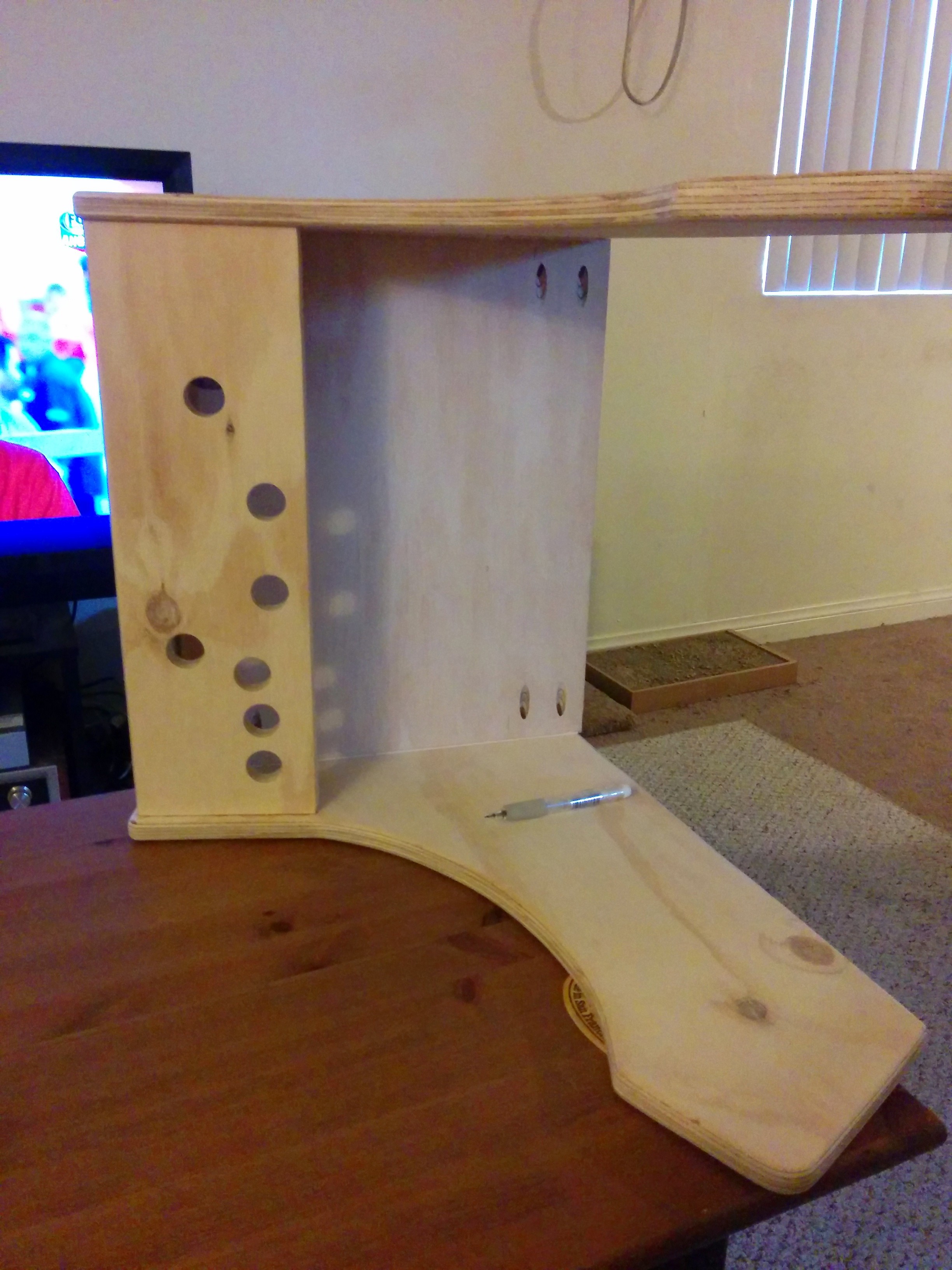
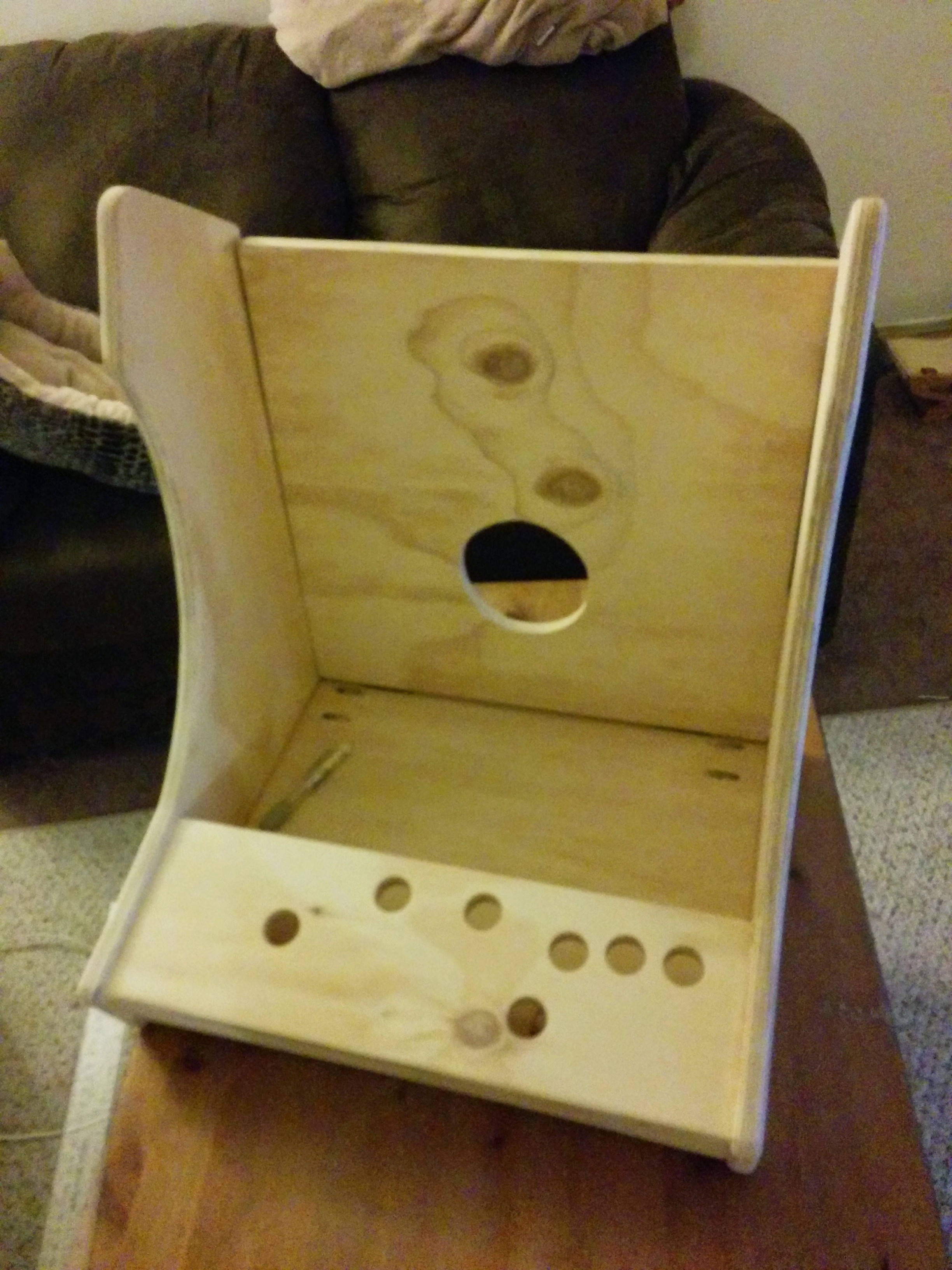
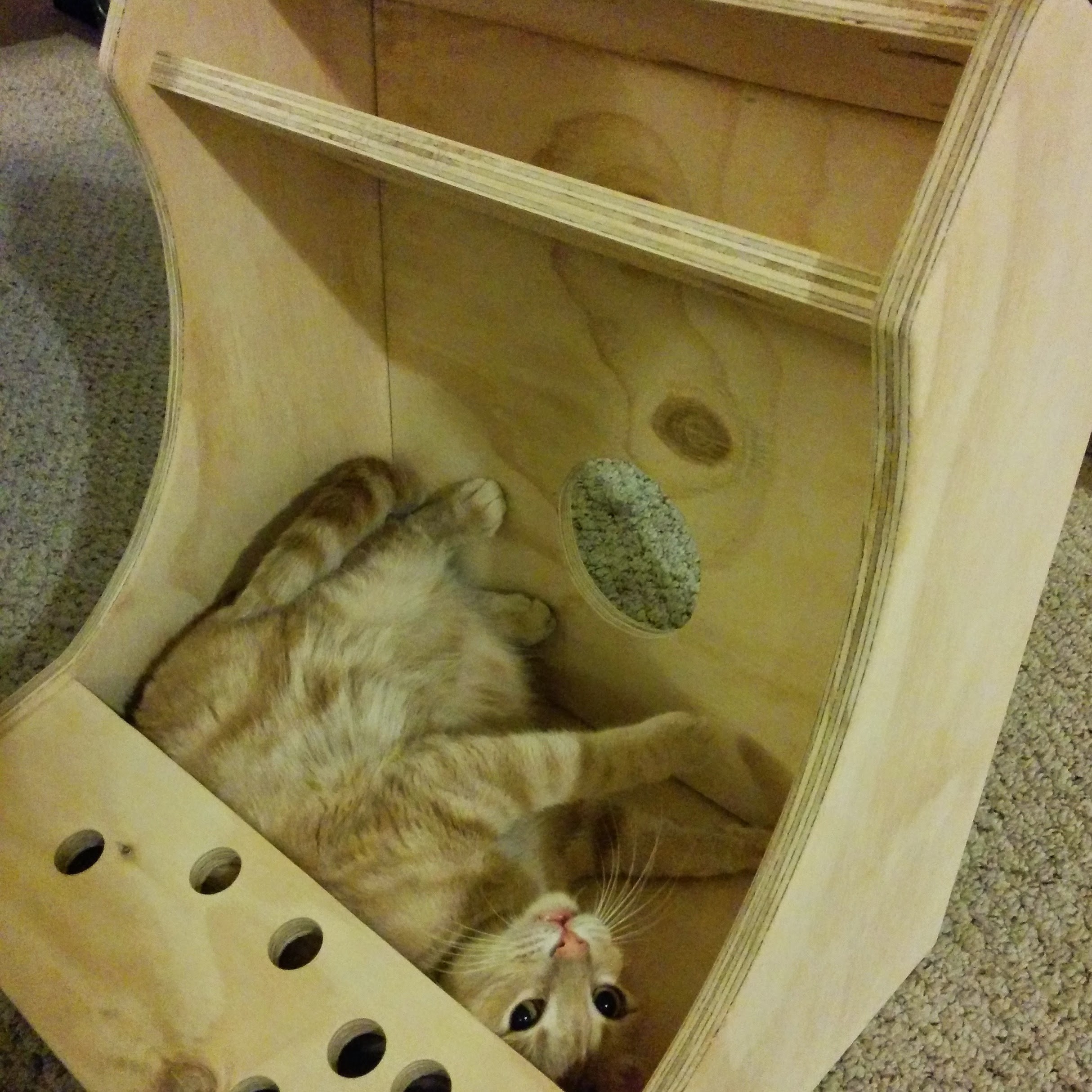
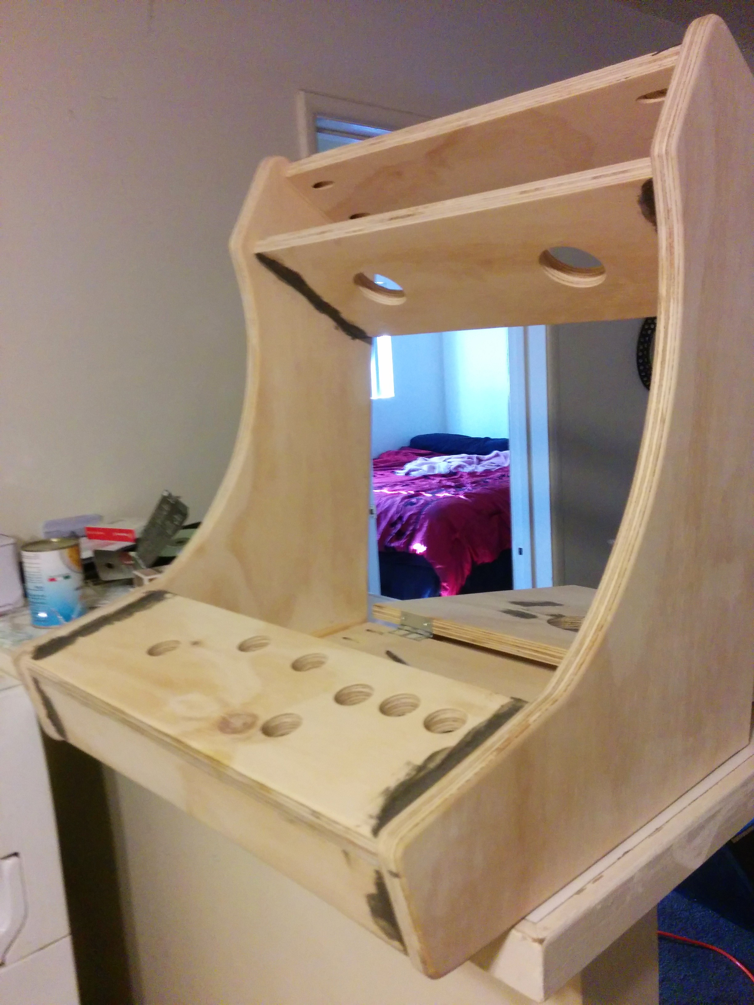
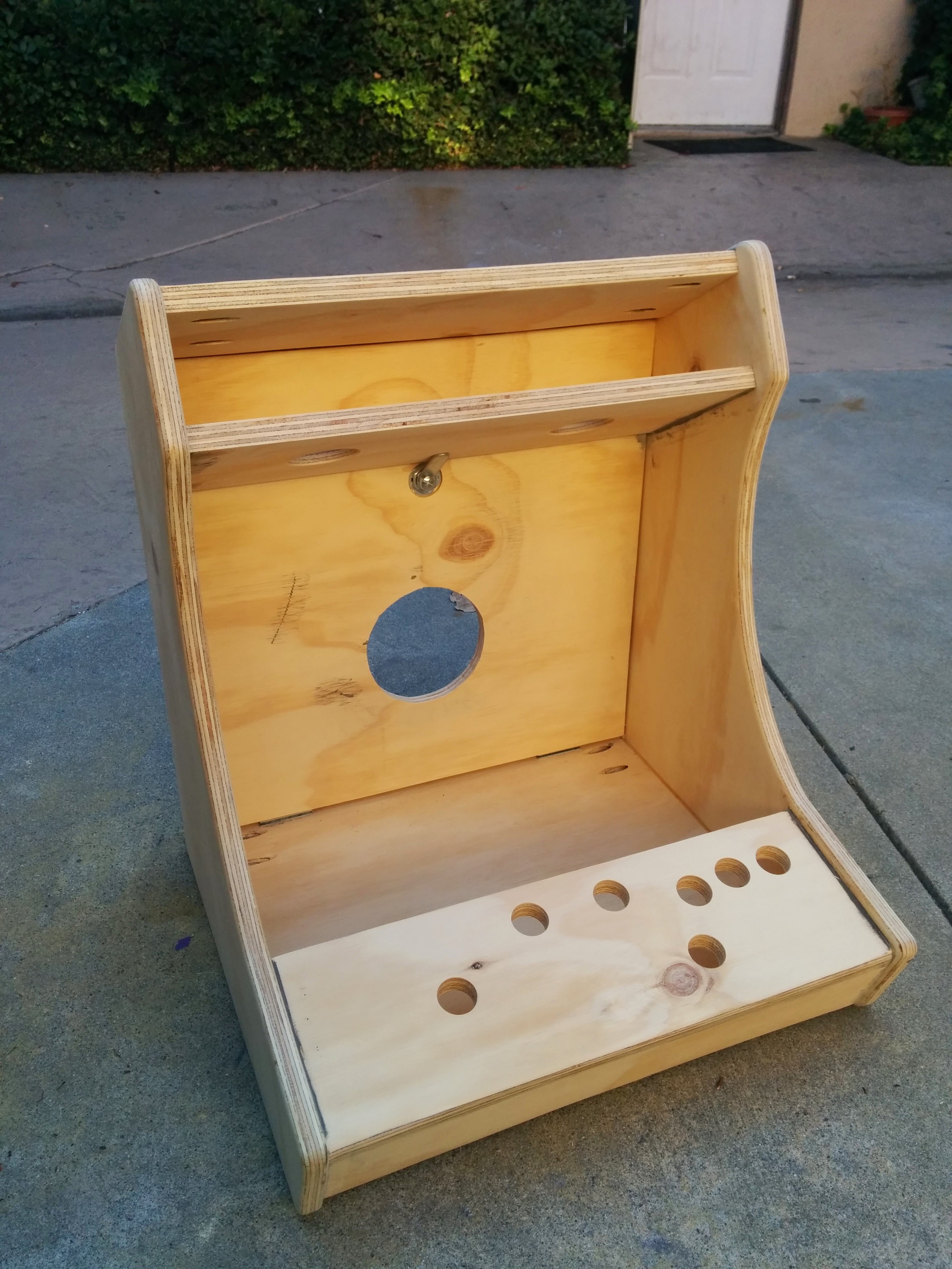
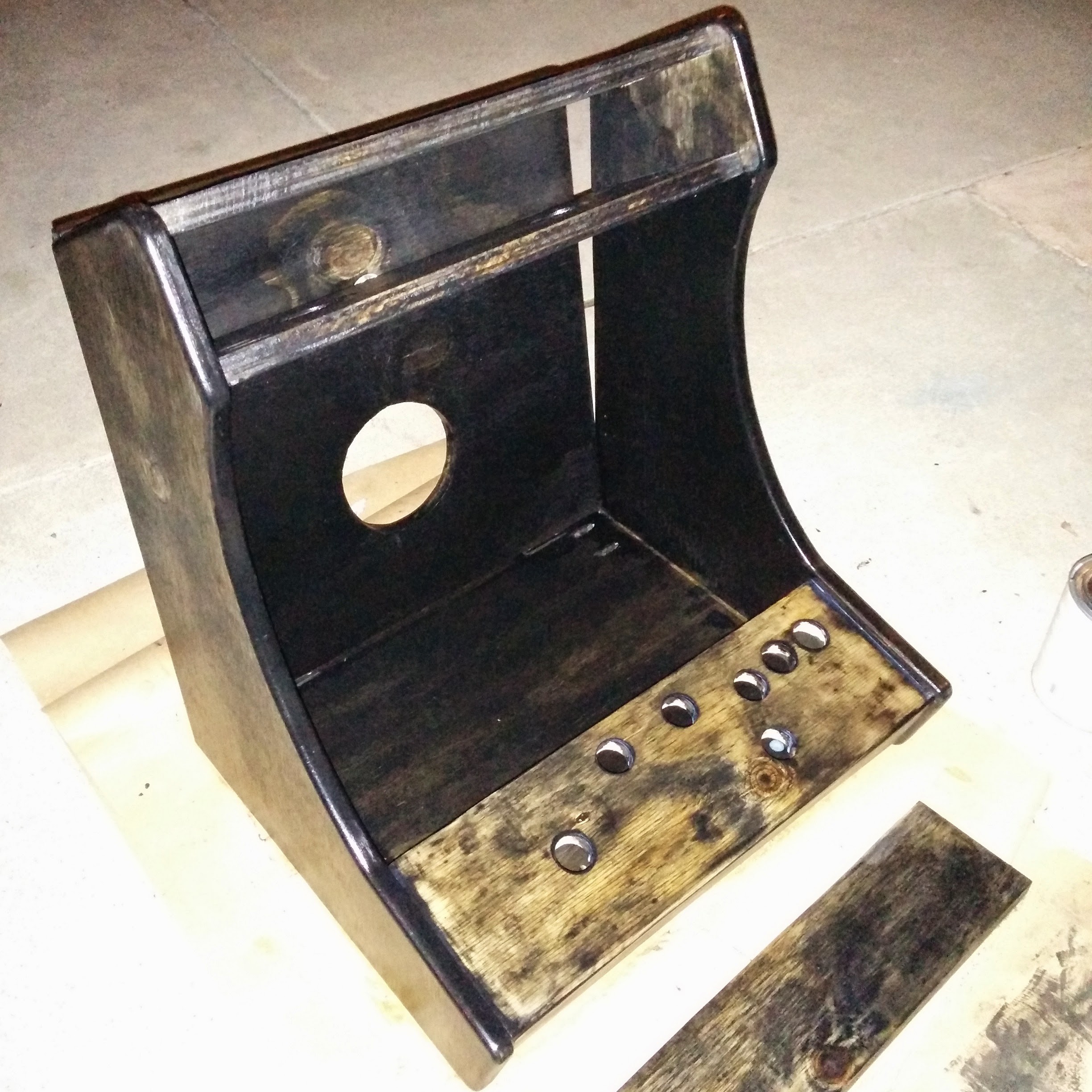
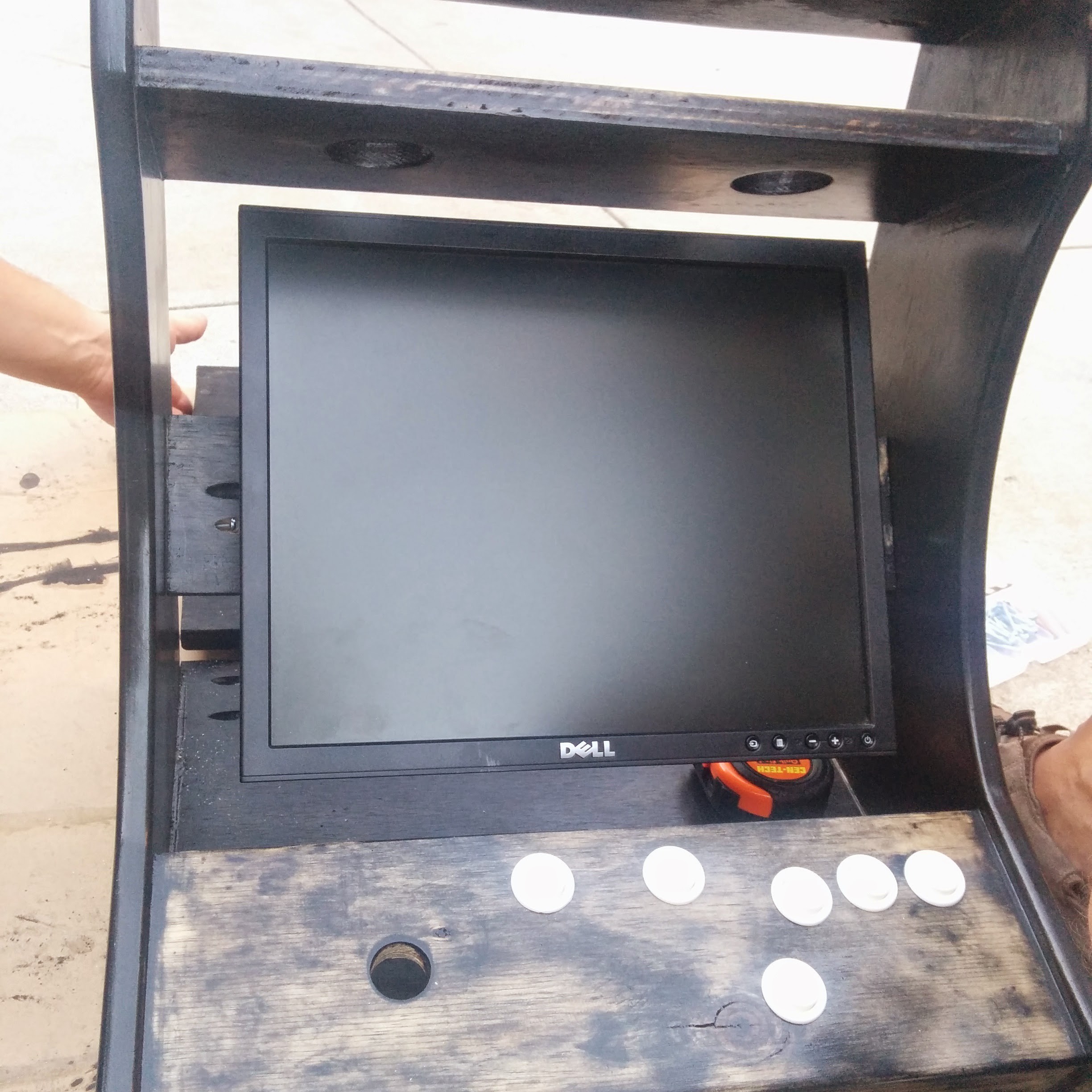
Building the Cabinet
At this point, you should have a fully functional Arcade System!
But you're going to want to mount the nest of wires and plugs into something nice looking, right?!
This part is mainly artistic, and will look as good as the effort you put into it!
I will provide insight, but it's mostly up to you!
![]()
![]()
![]()
![]()
![]()
![]()
![]()
![]()
![]()
![]()
![]()
![]()
![]()
![]()
Whats next? The Electronics of course. See all instructions for the Electrical.
-
4Step 4
Wiring the Joystick and Buttons into the Cabinet.
This will probably be the most time consuming part of the process, as you will want to customize your setup. Bust out your soldering iron and get to work!
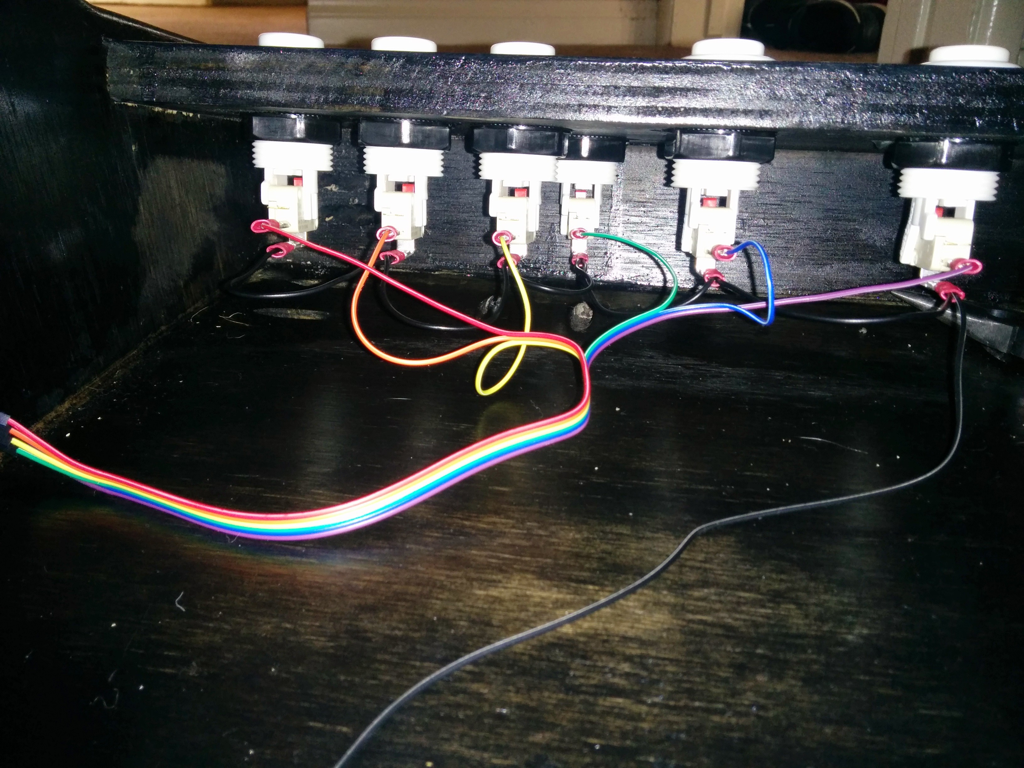
I chose to crimp the quick disconnect terminals to a female quick connect.
This will be a semi permanent setup that can easily be broken down if need be.
![]()
![]()
One end connects to the Arcade button, the other directly into the GPIO of the RPi
As for the other arcade button connection, it will be wired in a "daisy chain" for grounding all the buttons.
Check out that easy wiring setup ;)
![]()
![]()
![]()
![]()
Refer back to the GPIO diagram, and Retrogame file for button programming and wiring. Please feel free to comment if you get stuck or have any questions!
Write down which GPIO port you are plugging all the buttons into, you will need this later for programming the Retrogame file.
Please contact me if you have any questions or concerns
If you feel I left out a very important step in this build, let me know and I will add it ASAP!
I would be happy to assist anyone with technical help or build advice!Thank you for following!
Raspberry Pi Vintage Arcade
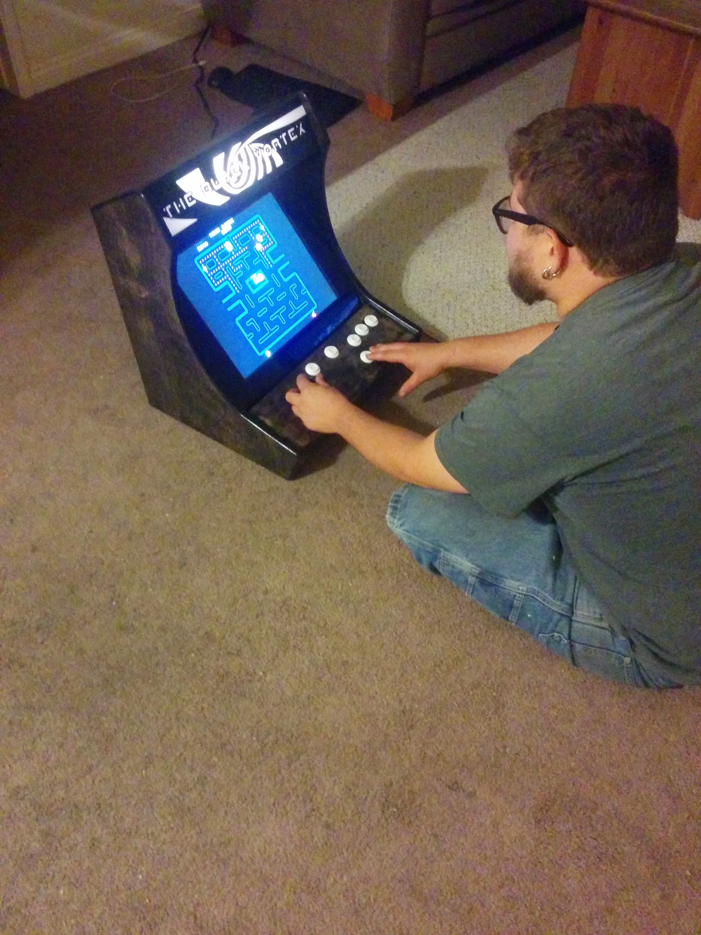
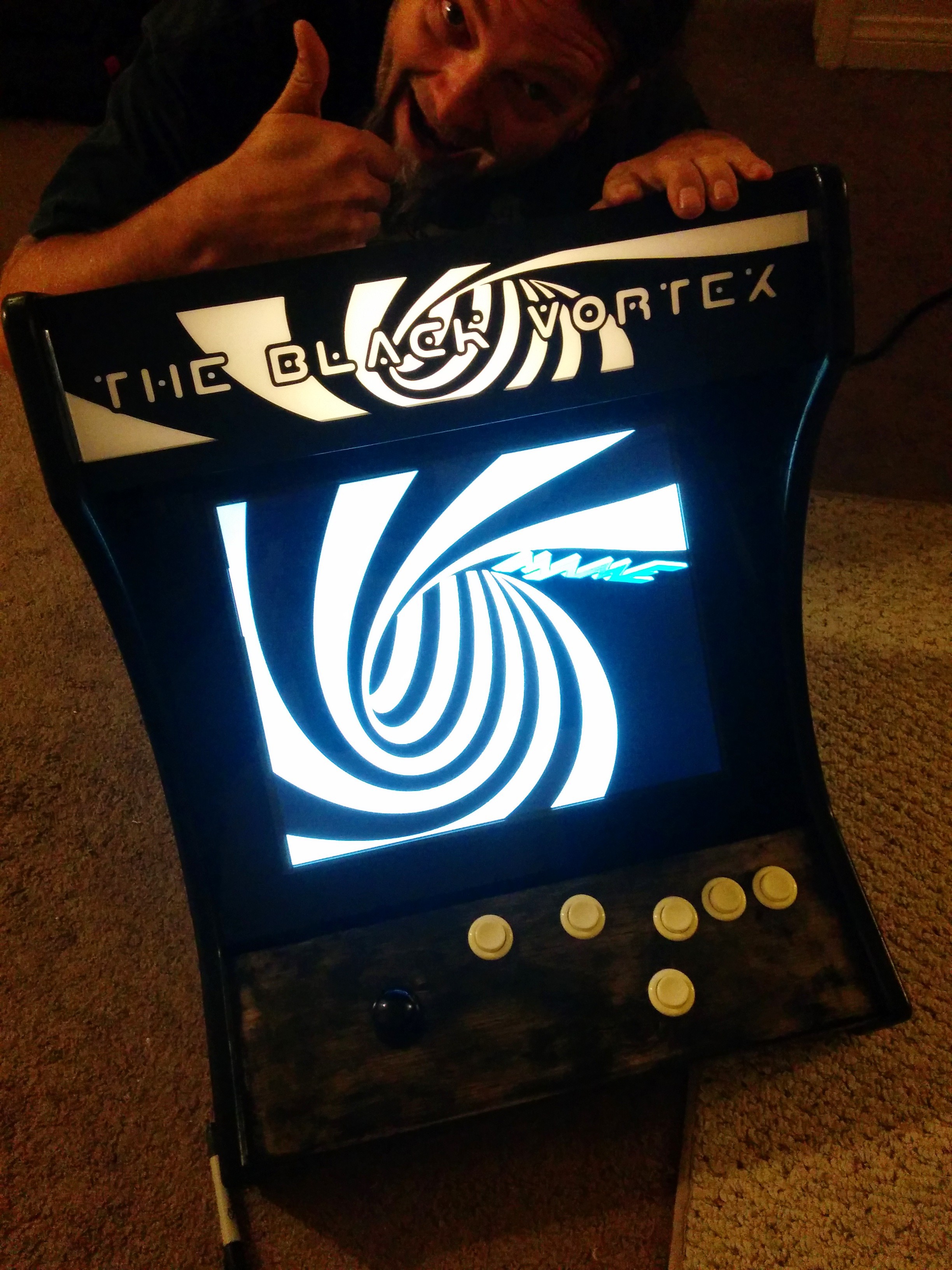
Classic yet original Arcade System built from the ground up, using a Raspberry Pi.
 Brayden DeVito








Discussions
Become a Hackaday.io Member
Create an account to leave a comment. Already have an account? Log In.
Hello , i have same question that zorblug about joystick software. Can you show how you did you acitved ?
Are you sure? yes | no
Can you give more information about the buttons, on the GPIO pinout, I see 1 joystick+2 buttons and on your front panel: 1 joystick and 6 buttons.
Thx,
Are you sure? yes | no