-
1Step 1
Setup:
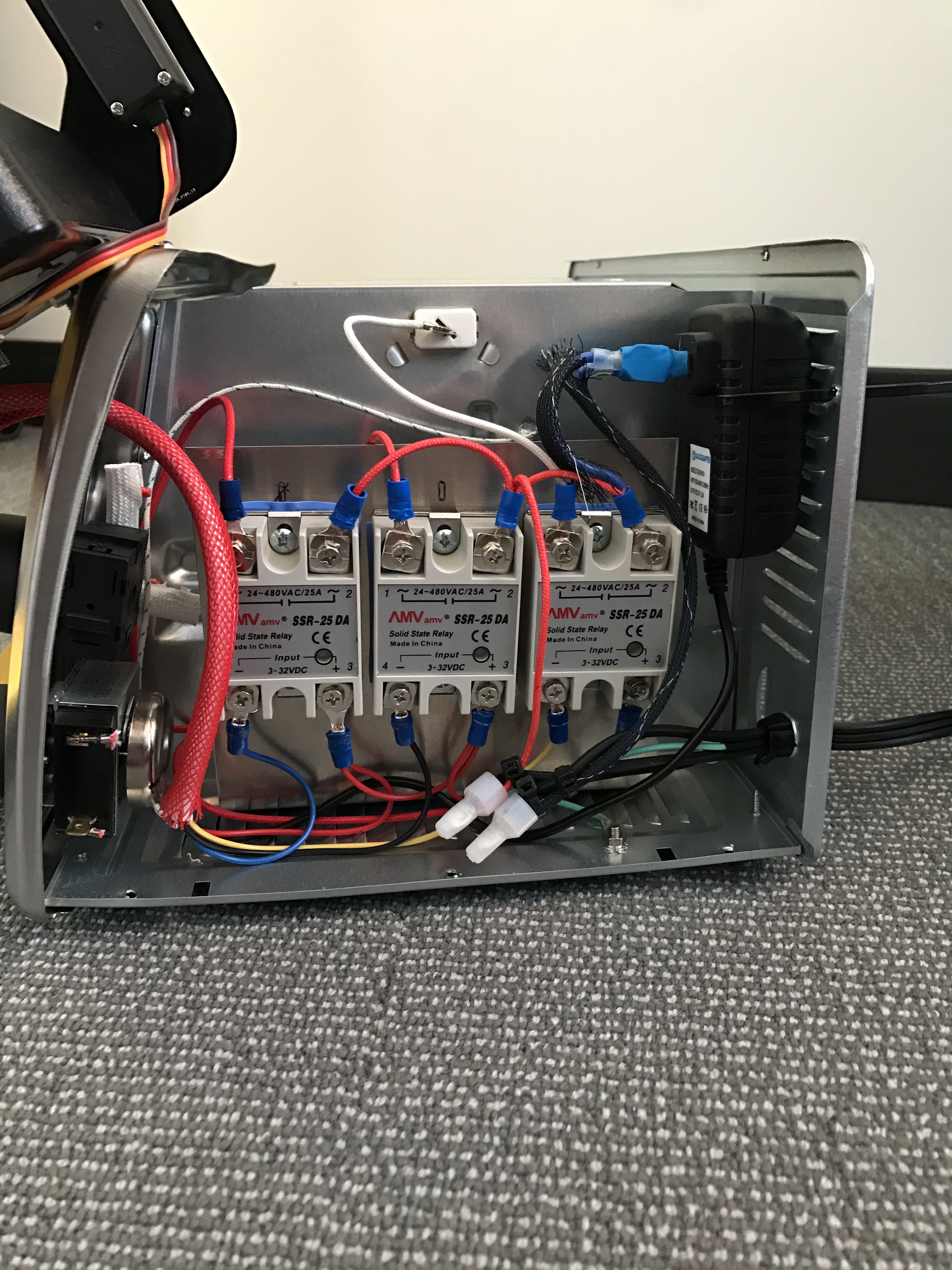
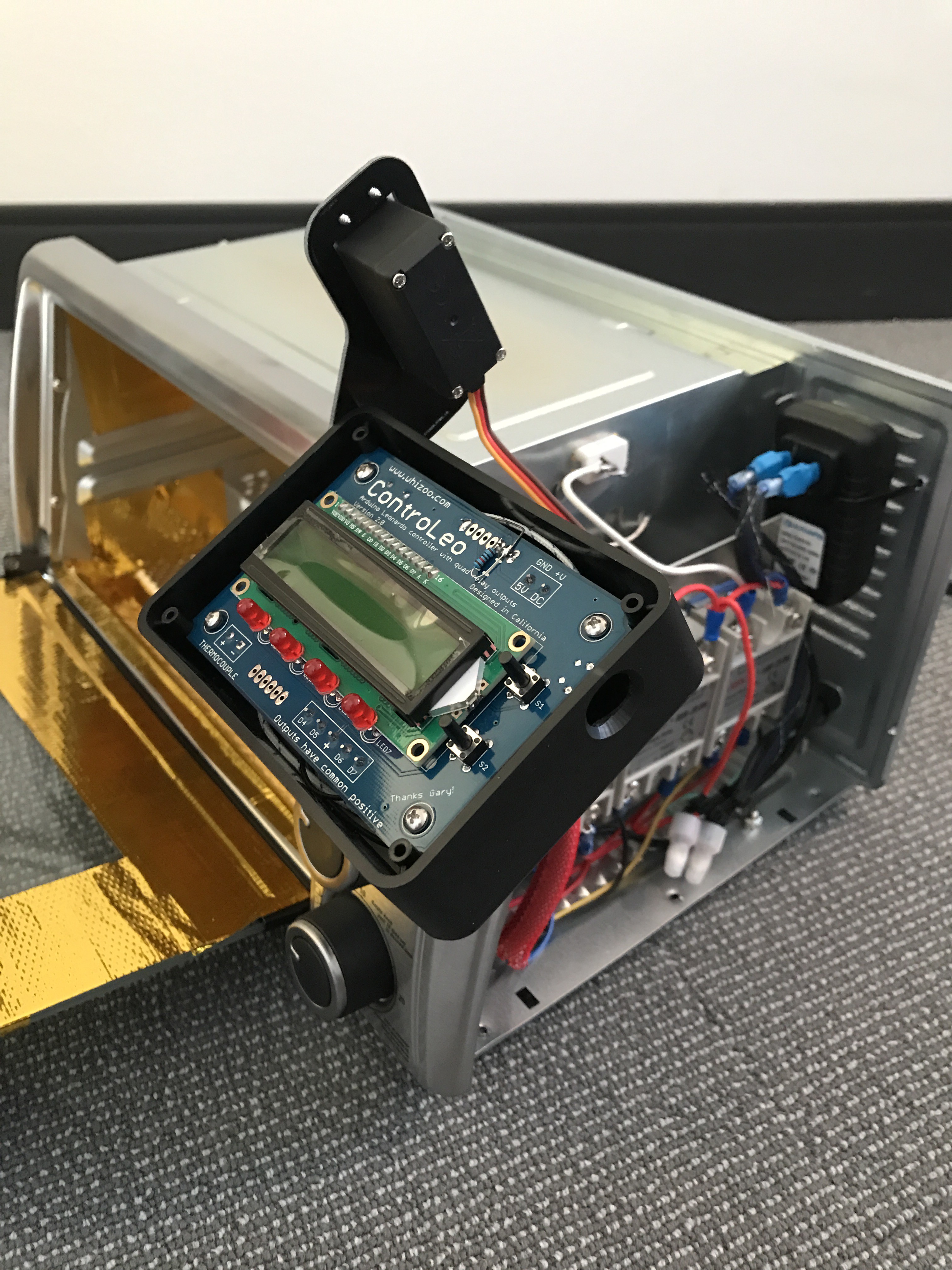
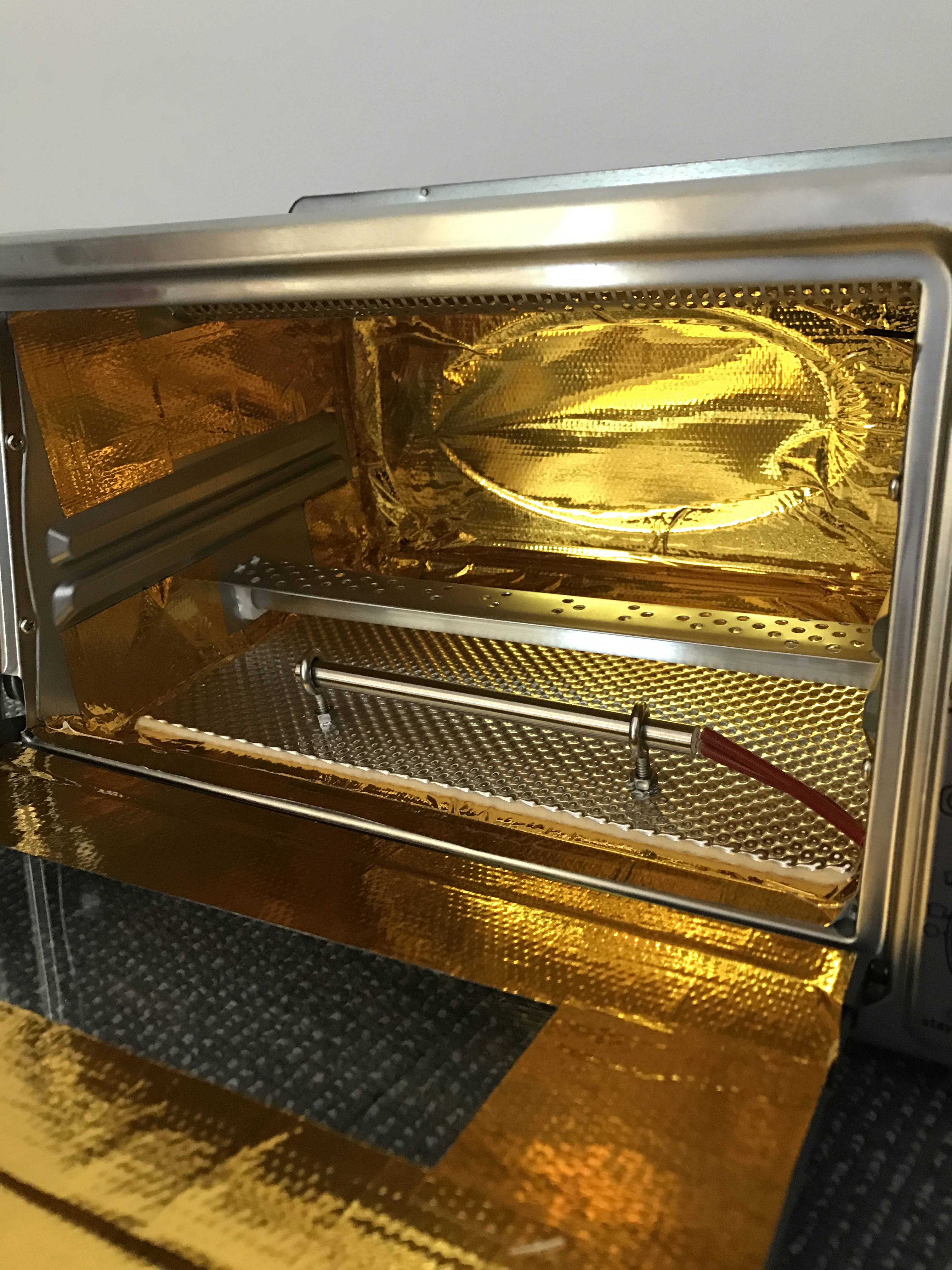
A requirement of this project is having the ability to reflow surface mount components on a PCB. I chose to go with the ControLeo2 Reflow Oven Controller. I ordered the full kit from their website Whizoo. I decided to use the exact same toaster oven that the tutorial on their website uses. This took some of the major unknowns out of the equation for the build. I bought the toaster oven off of Amazon for pretty cheap.
Some tips based on my experience of putting together the reflow oven:
- Read the full tutorial multiple times before starting to make sure you understand the process.
- Look at the pictures in the tutorial carefully. A couple of times I assumed I knew what the instructions were saying only to look at the pictures after doing something to realize I had done the step incorrectly.
- Avoid the temptation to work on steps out of order. I tried to skip ahead a couple of times thinking that I could save some time. This did not always work well. The tutorial has the steps in the best order.
- DON'T CUT THE WIRES UNTIL YOU ARE CERTAIN. You will need to reuse the wires you remove from the oven so do not cut them into sections for reuse without first making sure they are the correct length.
Here are some pictures of my final build of the reflow oven:
-
2Step 2
Raspberry Pi Compute Module 3 Lite:
The only design needed for using the Raspi CM3L is the power supplies, pull-up resistors for some of the I/O, and the micro-SD card slot. This setup is pretty straightforward following the schematics for the I/O board given here. A KiCAD project with a blank schematic for the CM3L can be found here. Customizing the board for a particular use then only requires adding whatever else is needed for the specific application.
-
3Step 3
Enabling the DPI on the Raspi CM3L:
I decided to drive the LCD display with the GPIO in case I wanted to make a dock for the handheld in the future. The dock would allow for HDMI out to a larger screen as well as a USB hub for Wifi and Bluetooth. This would enable updates to the device as well as wireless controllers for playing games on a bigger screen. To this end, using the GPIO to drive the screen keeps the HDMI lines free for future use.
Getting the screen to be driven by the GPIO was pretty straightforward. I suggest looking at the Raspi documentation here and a good tutorial here. The thing that I had to spend the most time on was the pixel timings. I tried using the exact frequency as suggested by the data sheet for the screen I was using. However, it turns out that the Raspi does not support arbitrary clock frequencies for this purpose. The only explanation I found is given here.
-
4Step 4
LCD Backlight Circuit:
Instead of trying to design my own circuit, I decided to take advantage of the open source nature of Adafruit. They have a boost circuit designed for their TFP401 board here. The only thing I discovered is that they did not update their schematic after the board went to production. The product number for the Zener diode they used is incorrect. Version 3.0 of my board uses the exact diode the schematic mentions but it burned out the diode. After reading some data sheets and doing some math, I discovered that the Zener diode in the Adafruit schematic does not have a high enough power rating. It should be rated for at least 600mA and the one reference in the schematic is only rated for 300mA! Just something to keep in mind.
For those wondering, the Zener diode is only there to prevent the boost IC from frying itself in the feedback loop is left open. If you plan to always have the screen plugged in when the IC has power, then the Zener diode is not necessary. Check the data sheet for the boost IC.
-
5Step 5
Enabling GPIO Keyboard:
There are a couple of different ways to get the GPIO pins to function as a keyboard. The first is to follow the guide posted by Adafruit. I didn't love this approach since it requires third party software running on the device. I therefore decided to use a device tree overlay that is supported by Debian Linux. A great explanation of device tree overlays is given here. The trick to getting the keyboard recognized by EmulationStation is to add a udev rule as outlined on the Adafruit GitHub page linked above.
Here is a video of the buttons working in RetroPie:
Raspberry Pi CM3L Single Board Handheld
Single board design for a RetroPie handheld gaming device.
 tmtr creations


Discussions
Become a Hackaday.io Member
Create an account to leave a comment. Already have an account? Log In.