 Adellar Irankunda
-
1Step 1
Building the Circuits
The project requires the assembly of 4 fairly similar sensor/emitter circuits (which will be referenced as Hubs 1-4) and a mouse circuit (which will be referenced as Hub 5). Luckily enough, you are not tasked with designing these circuits (that was my job J), I have provided circuit diagrams to aid with the assembly process as well as code specified to run on each hub. What is required of you is to follow the circuit diagrams and build the circuits, then to upload their respective programs and start using the interface. Hubs 1-4 are similar in that they all use the Arduino Nano and they contain infrared phototransistors and emitters. The job of these hubs is to create an XY grid of infrared sensors and send information to Hub 5 when they ‘think’ there is a touch present.
As mentioned before, Hubs 1-4 are similar in design, so their Fritzing diagrams are similar, save for a few differences in wiring, please pay attention to the different wiring, especially between Hubs 1 & 2 the rest (Hubs 1 & 2 are a little more intricate than Hubs 3 & 4); these differences are due to functionality differences which will be explained later on. In the process of assembling Hubs 1-4, it is wise to start by referencing Fritzing diagrams 1-4 as the different diagrams represent different steps in the building process, with more components being added onto the breadboards. The best way to build the four hubs efficiently is to build the 4 hubs all at once, instead of finishing one and then moving to the next (start building all 4 at once and make equal progress on all 4 as you are observing the diagrams). The Fritzing Diagrams with details on how to build the 5 hubs can be found in the images alongside each step. Please do not concern yourself with matching the wire colors as they appear in the schematics.
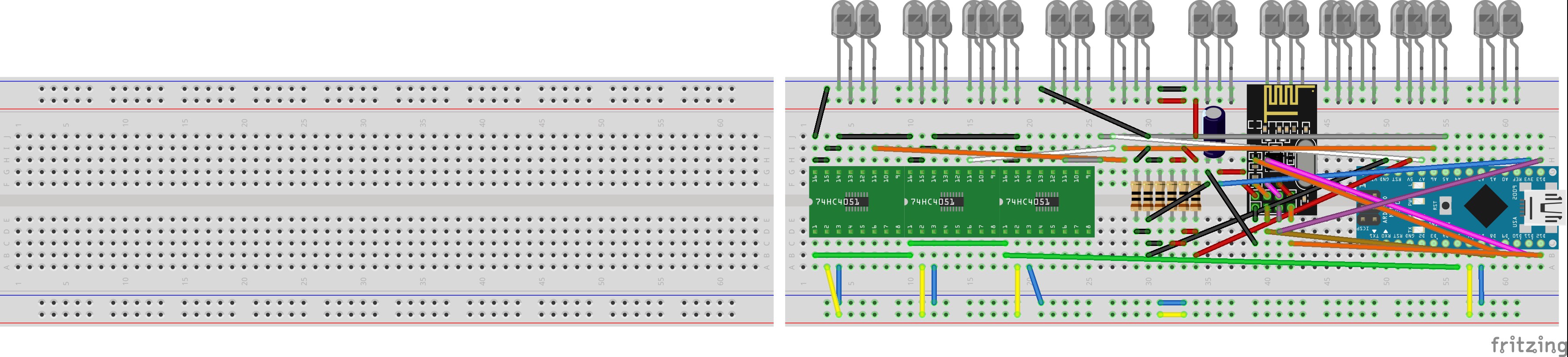
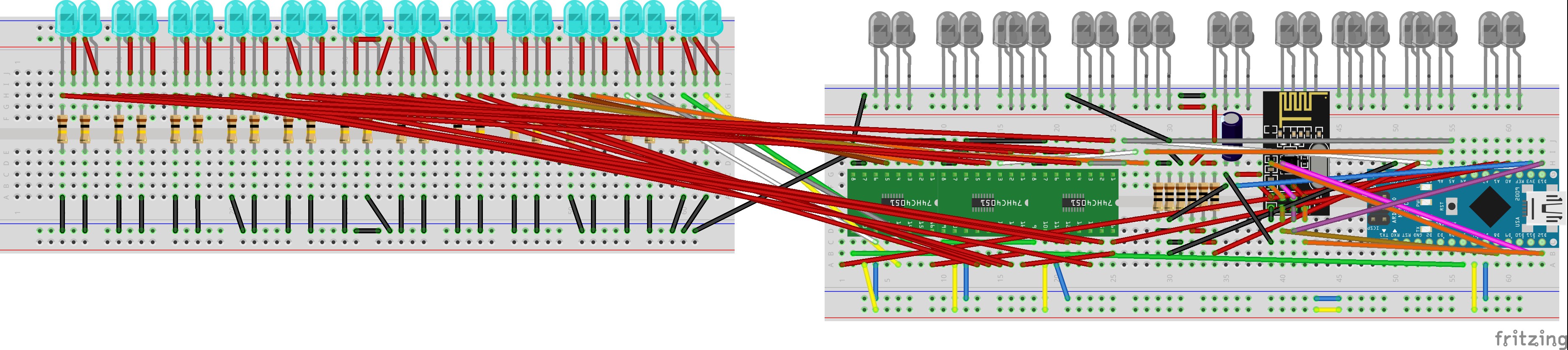
- Step1 -This is the first step in building the 4 primary hubs, they should all start out looking like this. The green ICs that are marked 74HC4051 represent the 4051 multiplexers, yours should look like completely black ICs, despite the difference in looks, the wiring is the same.
![]()
- Step 2 -This is the second step to the 4 primary hubs, in this step we just add more components to the circuits for Hubs 1-4 we have started to make. At this point, all the Hubs are identical in the wiring.
![]()
- Step 3 (Hubs 1 & 3) - On this step, hubs 1&3 start to look different from 2&4, wiring the phototransistors to the multiplexers is different for hubs 1 &3 so please make sure you only make these adjustments for 2 of the 4 circuits you are working on. Those 2 circuits you make these adjustments to are now going to be referred to as 'Hubs 1 & 3'.
![]()
- Step 3 (Hubs 2 & 4) - In the last step (step 3 (hubs 1 &3)) we made adjustments to hubs 1 & 3, now we have to make changes to Hubs 2 & 4 so that they are unique from 1 & 3. Take the remaining circuits (excluding 1 & 3) and make the following adjustments to them. Those 2 circuits you make these adjustments to are now going to be referred to as 'Hubs 2 & 4'.
![]()
- Step 4 (Hubs 1 & 3) - In Step 3 (Hubs 1 & 3), we wired up half of a multiplexer with 4 phototransistors, now we are going to hook up another 4 for Hubs 1 & 3 each. Notice that the previous connections we made on Hubs 1 & 3 do not appear in this image, some connections were taken off so that you may clearly view the connections for the second set of 4 transistors. You should not remove the connections made for the first 4 phototransistors in step 3 (Hubs 1 & 3), merely add these connections to the hubs.
![]()
- Step 4 (Hubs 2 & 4) - In Step 4 (Hubs 2 & 4), we wired up half of a multiplexer with 4 phototransistors, now we are going to hook up another 4 for Hubs 2 & 4 each. Notice that the previous connections we made on Hubs 2 & 4 do not apper in this image, some connections were taken off so that you may clearly view the connections for the second set of 4 transistors. You should not remove the connections made for the first 4 phototransistors in step 3 (Hubs 2 & 4), merely add these connections to the hubs.
![]()
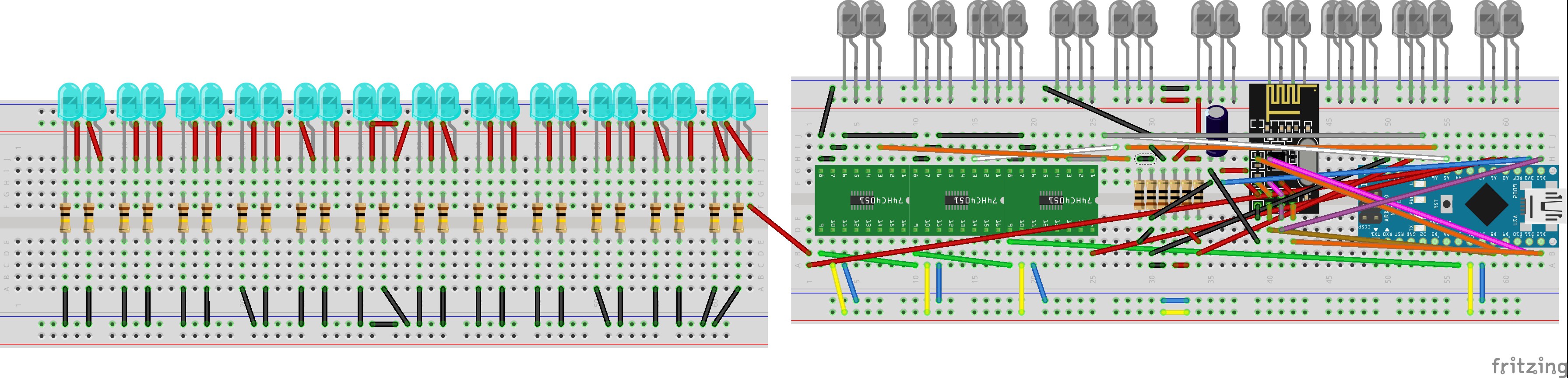
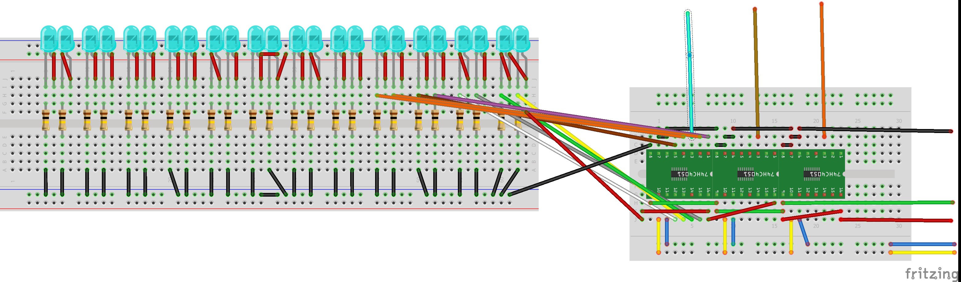
- Step 5 (Hubs 1 & 3) - In step 4 (Hubs 1 & 3), we completed the connections for one multiplexer and 8 corresponding phototransistors. Now, we are going to connect the 3 remaining multiplexers to the 16 remaining phototransistors in the same fashion we hooked up the first 8 phototransistors to the first multiplexer. The image is crowded with wires, but this is to show how the finished product of all the multiplexers hooked up to the phototransistors should look like. If you cannot remember how to hook up the rest of the phototransistors, please refer back to step 3 (Hubs 1 & 3) and step 4 (Hubs 1 & 3).
![]()
- Step 5 (Hubs 2 & 4) - In step 4 (Hubs 2 & 4), we completed the connections for one multiplexer and 8 corresponding phototransistors. Now, we are going to connect the 3 remaining multiplexers to the 16 remaining phototransistors in the same fashion we hooked up the first 8 phototransistors to the first multiplexer. The image is crowded with wires, but this is to show how the finished product of all the multiplexers hooked up to the phototransistors should look like. If you cannot remember how to hook up the rest of the phototransistors, please refer back to step 3 (Hubs 2 & 4) and step 4 (Hubs 2 & 4).
![]()
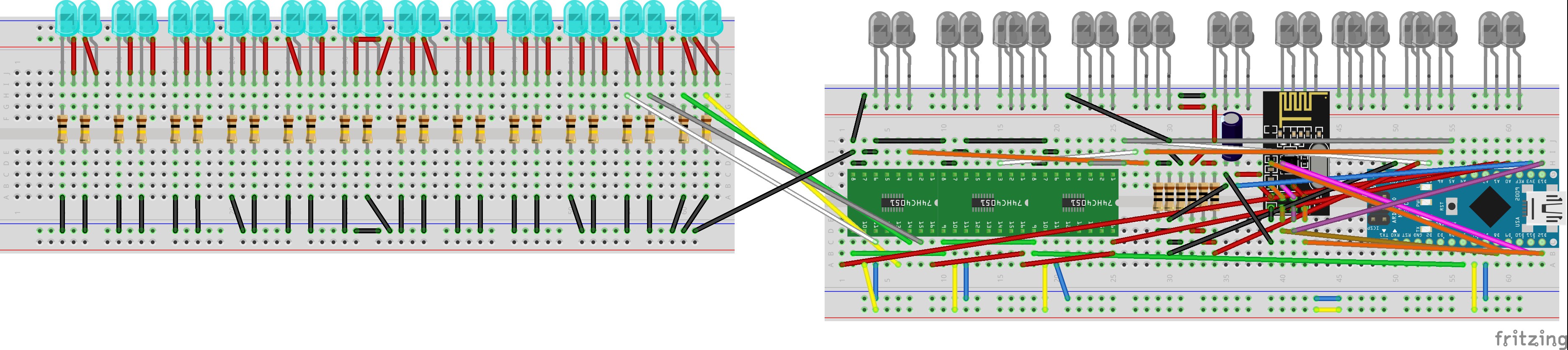
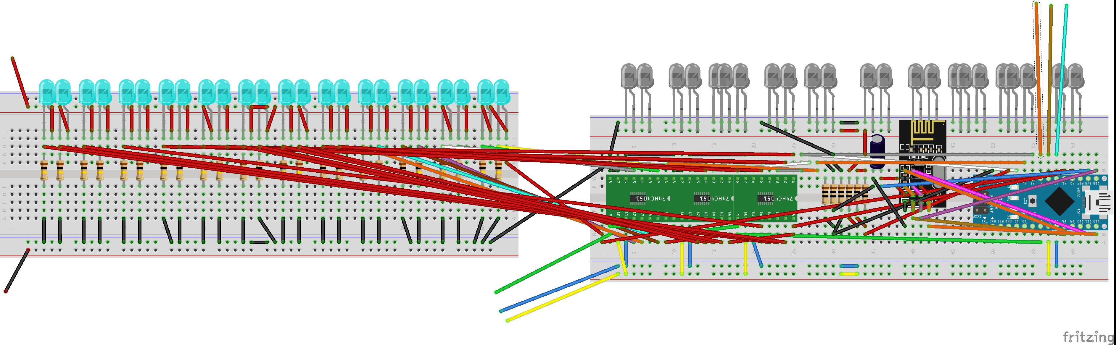
- Hub 1 Modular - In order to build a modular system, we need to make adjustments to Hub 1 (you can pick which one of Hub 1 and 3 is "1" because they should be identical at this point) so that it can accept more receiver hubs. In order to do this, we extend some of the connections and leave the wires hanging off of the breadboard using male to female wires (the male end should be in contact with the breadboard and the female end should be hanging off of the breadboard). We do this for 8 connections as shown.
![]()
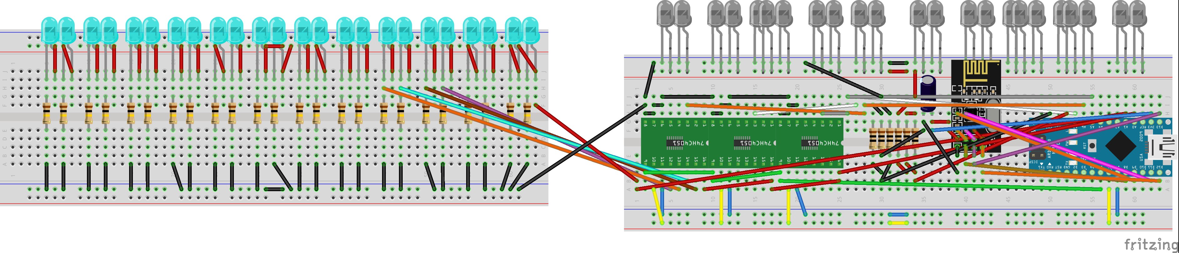
- Hub 2 Modular - In order to build a modular system, we need to make adjustments to Hub 2 (you can pick which one of Hub 2 and 4 is "2" because they should be identical at this point) so that it can accept more receiver hubs. In order to do this, we extend some of the connections and leave the wires hanging off of the breadboard using male to female wires (the male end should be in contact with the breadboard and the female end should be hanging off of the breadboard). We do this for 8 connections as shown.
![]()
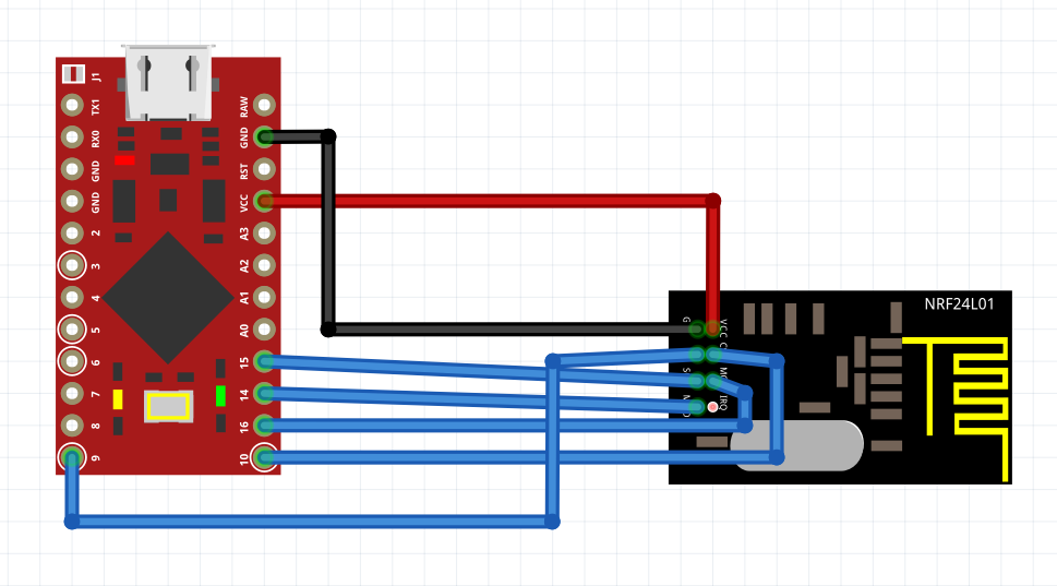
- Hub 5 - This is the wiring for Hub 5, it is the most straightforward as it is composed of the Pro Micro and the NRF24L01. You may use the female to female jumper wires to connect the two devices together.
![]()
- Step1 -This is the first step in building the 4 primary hubs, they should all start out looking like this. The green ICs that are marked 74HC4051 represent the 4051 multiplexers, yours should look like completely black ICs, despite the difference in looks, the wiring is the same.
-
2Step 2
Building Extension Modules
- Receiver Extension Module (Hub 1) -Now that Hubs 1-4 are complete in wiring, we can create the extension receiver hubs that can attach to hubs 1 and 2 to increase the number of receivers on the system (effectively increasing the physical resolution of the system). We create an extension module with the multiplexers on the small breadboard. Complete the connections for the multiplexers to the phototransistors the same way you did for Hub 1 and its phototransistors and multiplexer connections.
![]()
- Receiver Extension Module (Hub 2) -
Now that Hubs 1-4 are complete in wiring, we can create the extension receiver hubs that can attach to hubs 1 and 2 to increase the number of receivers on the system (effectively increasing the physical resolution of the system). We create an extension module with the multiplexers on the small breadboard. Complete the connections for the multiplexers to the phototransistors the same way you did for Hub 2 and its phototransistors and multiplexer connections.![]()
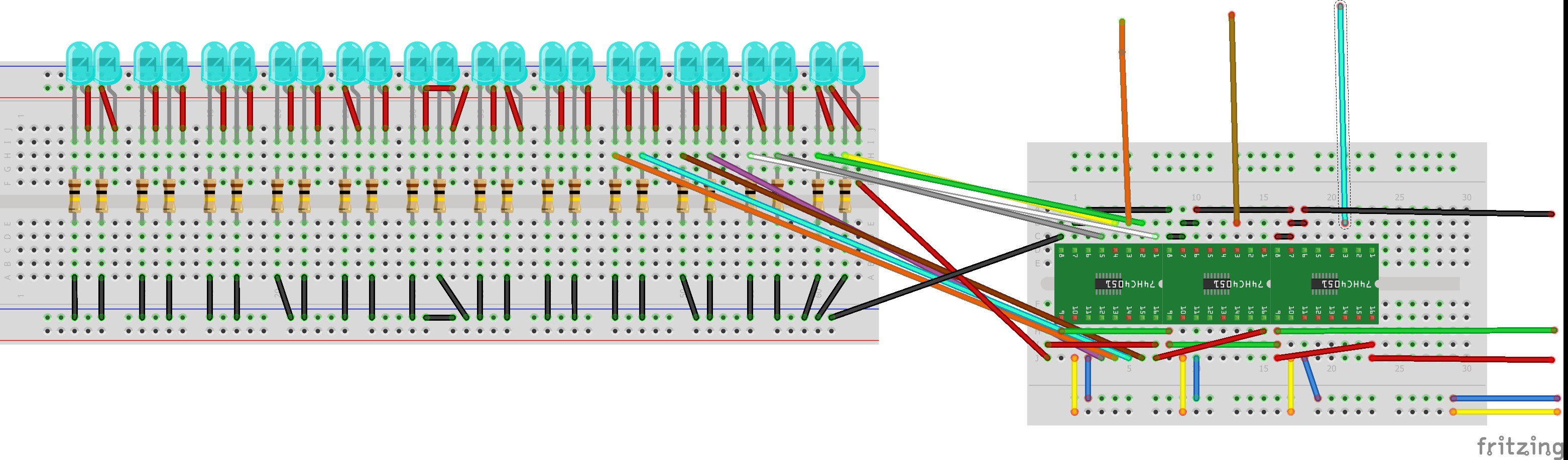
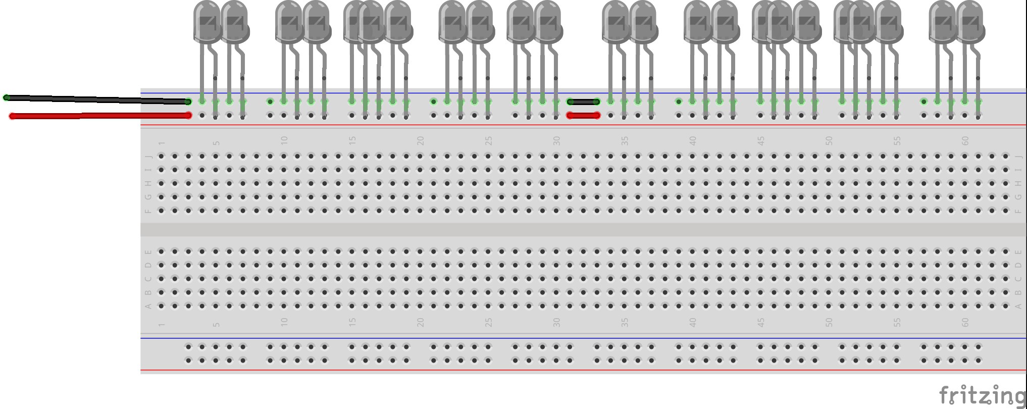
- Emitter Extension Module (Hub 3 & 4) -
We have created Hubs 1-4 and receiver extension modules for Hubs 1 and 2, now we need to create emitter extension modules for Hubs 3 & 4. The wiring for these modules is fairly straightforward, just make sure that you leave two wires hanging off of the two terminals as shown in the images. Create two of these circuits (for Hub 3 and 4) and ensure they each have the two wires so that they may attach to their respective hubs.![]()
- Receiver Extension Module (Hub 1) -Now that Hubs 1-4 are complete in wiring, we can create the extension receiver hubs that can attach to hubs 1 and 2 to increase the number of receivers on the system (effectively increasing the physical resolution of the system). We create an extension module with the multiplexers on the small breadboard. Complete the connections for the multiplexers to the phototransistors the same way you did for Hub 1 and its phototransistors and multiplexer connections.
-
3Step 3
Hub, Module, and Extension Orientation
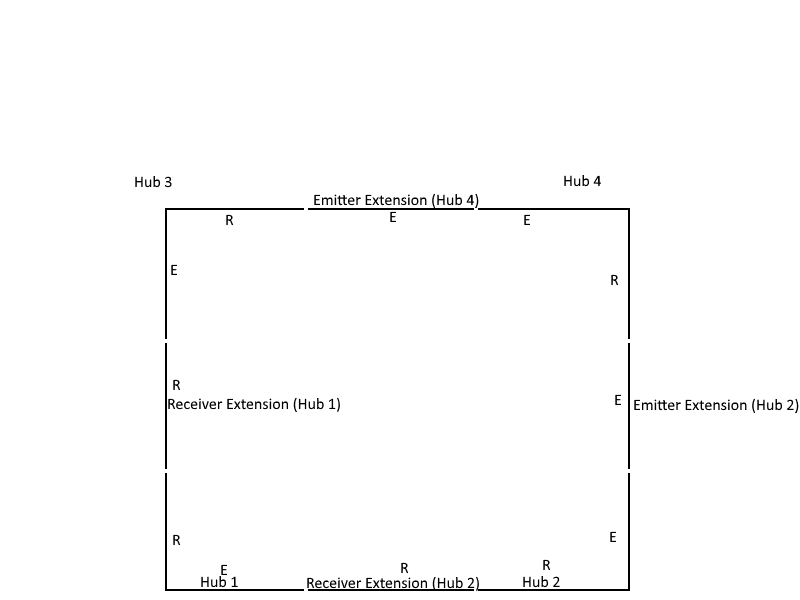
In order to orient the modules and the hubs correctly, I created a visual that shows how the different modules face each other. The modules are oriented with Hub 1 being in the bottom left, Hub 2 in the bottom right, Hub 3 at the top left, and Hub 4 at the top Right. Connect receiver extension modules to their respective Hubs via with the male headers coming off of the extension matching their female counterparts (visible through color coding of the diagrams) and the emitter extensions with their respective hubs in the orientation in the image (use the color coding again to determine how to connect the modules together). The photo in this step exists to help you see a real life depiction of the modules and their extensions connected together.
![]()
![]()
-
4Step 4
Uploading Programs
Code -
After building the different hubs and the extension circuits that go with them, please download the zipped files in this section, "touch_interface.zip". In this archive, there are 5 programs, use the Arduino IDE to upload them to their respective hubs.
Code links (If you do not want to download the zipped archive)
Hub 1:
Hub 2:
Hub 3:
Usage -
In order to use the Hubs and their modules, it is necessary to open up each one of the Arduino’s (Hub’s) serial monitor. Within the code there are some commands that allow the user to calibrate the touch interface via serial communication (serial monitor). After getting the orientation right, and having the serial monitor open, send the letter ‘n’ in the serial monitors corresponding to Hubs 1-4. Ensure that the output of each hub has a table that matches the number of sensors that it covers (if the hub has a receiver extension module, the table should display 48 elements, and otherwise it should be 24). Send the command ‘ar’ and create shadows over the interface (do not obstruct the path between a receiver and emitter), merely create shadows over the receivers and the ambient light (not from the emitters). After 1 minute, calibration will be finished and the 4 Hubs will transmit touch data between themselves and the computer that Hub 5 is connected to. Hub 5 does not have to be connected to the same computer Hubs 1-4 are connected to, but the serial monitor for Hub 5 has to be open on that computer.
Inexpensive Wireless Interactive Touch Interface
This is a wireless touch interface that costs $50 make. The interface is also modular which means it can be expanded or shrunk.


Discussions
Become a Hackaday.io Member
Create an account to leave a comment. Already have an account? Log In.