Here you can see all the functions. You can turn on the indicator for the second or turn it off. When the LED in the middle blinks at 1Hz you can see the status of the battery (here around 75%), when it blinks at 2Hz you can set the time (hours, minutes, seconds), then set the on-time (how long does the watch show the time, after the button was pressed), the time correction (manual time correction to increase the gang accuracy) and you can change the way how the time is displayed (one point or everything filled up starting at 12). The last menu is just for testing the LEDs.
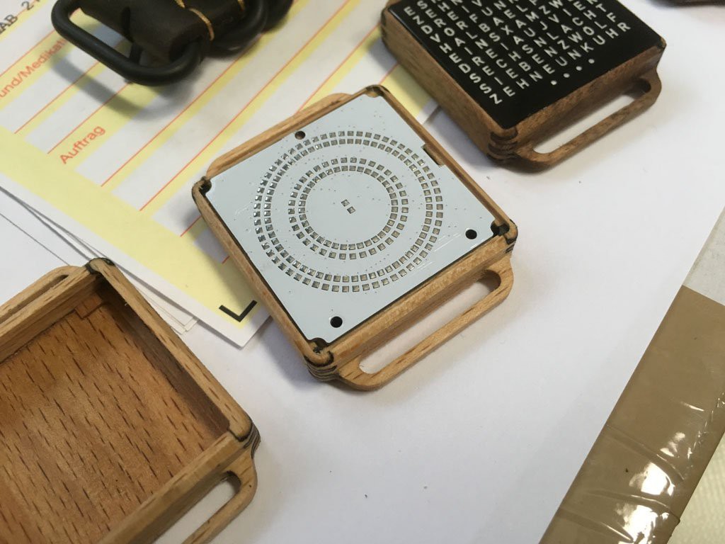
I've also some new PCBs with a better battery holder. There is also a new version with squared shape.
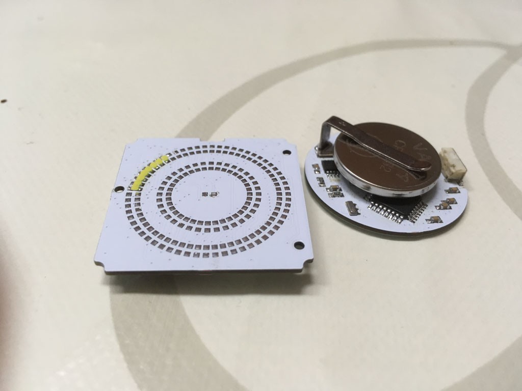
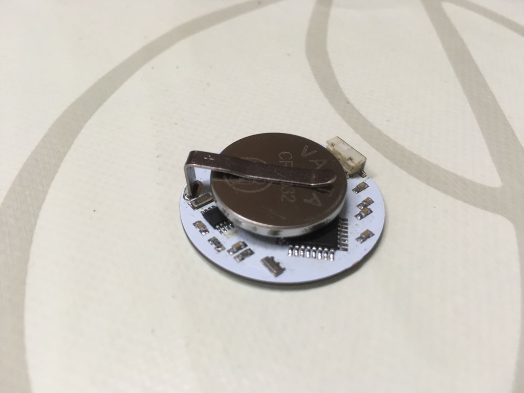
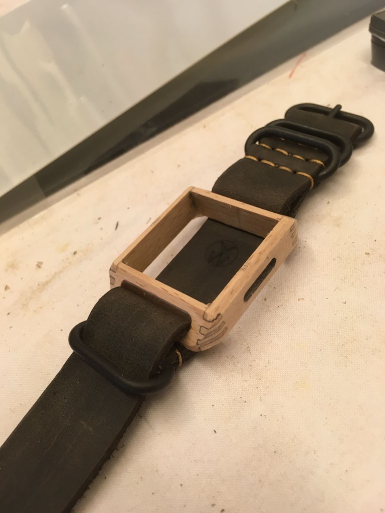
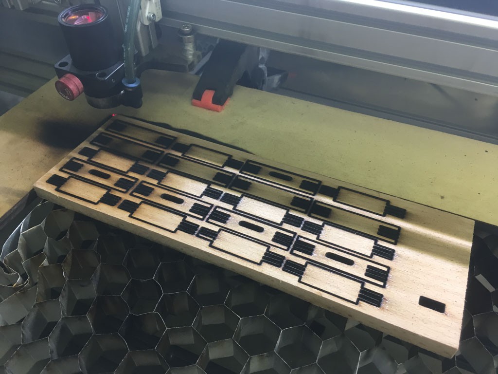
A first test for new housings for the squared PCB:
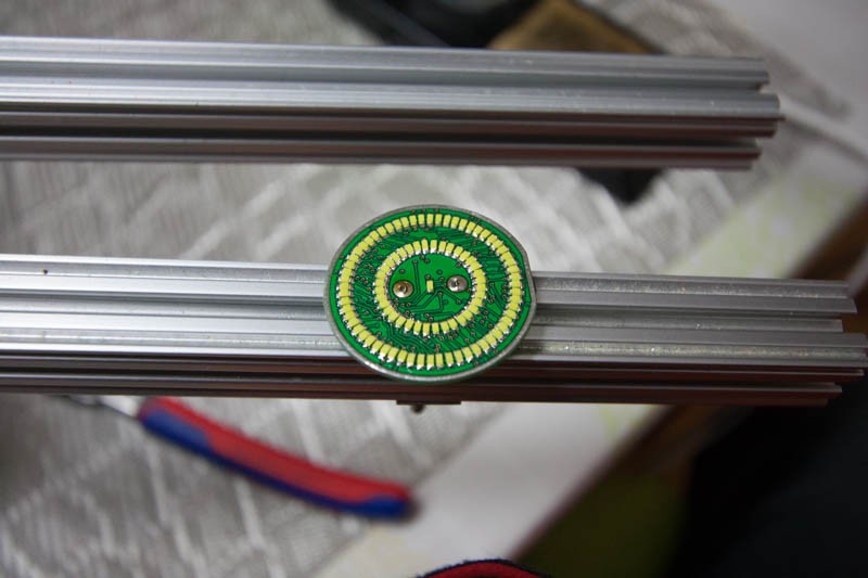
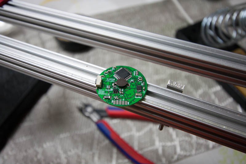
Pictures of the soldering instruction:


 bobricius
 Raunaq Bose
 Paul Stoffregen
Hey, I am curious to know how did you get the led's to be that tiny on the board? Is it possible to direct me toward any possible source where I can learn to implement a similar pcb layout in horizontal form instead of the circular dial design that you have there.