 Miroslav Zuzelka
This is my last revision which a did so far.
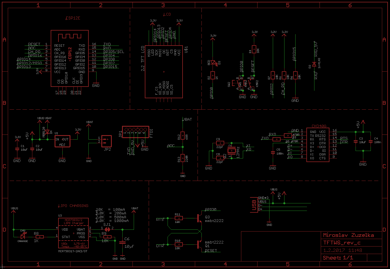
It contain following parts:
- ESP12E
- 3.3V voltage regulator LM1117
- Reset button
- Flash button
- FTDI connector
- LCD connector
- Some resistors
- Some capacitors
- LED for flash state
- build in charging with MCP73831T + LED indicator
- auto-reset feature
- USB to Serial converter chip CH340G
Charging & auto reset circuit is copy of same circuit which Adafruit have on Adafruit Feather HUZZAH with ESP8266 WiFi . USB to Serial part is from Nodemcu github documentation page. Because I want in the future monitor battery voltage (when board is not connected to power source), I placed 2 resistors on analog input of ESP and connect it to battery positive contact. This way I can monitor how much voltage is comming from battery and possibly send message that battery should be connected to power source.
Here is schematic:
Board design:
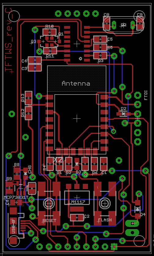
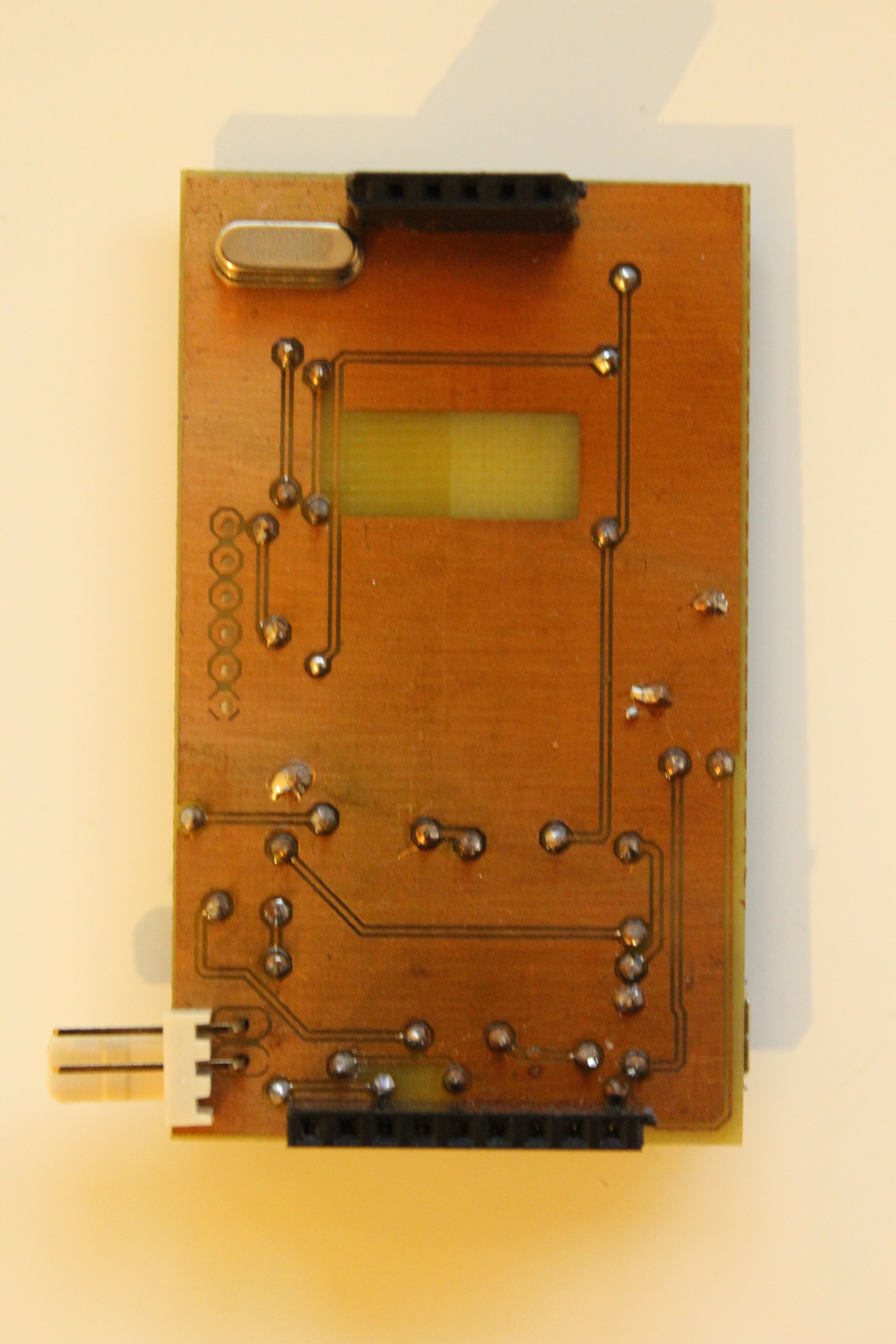
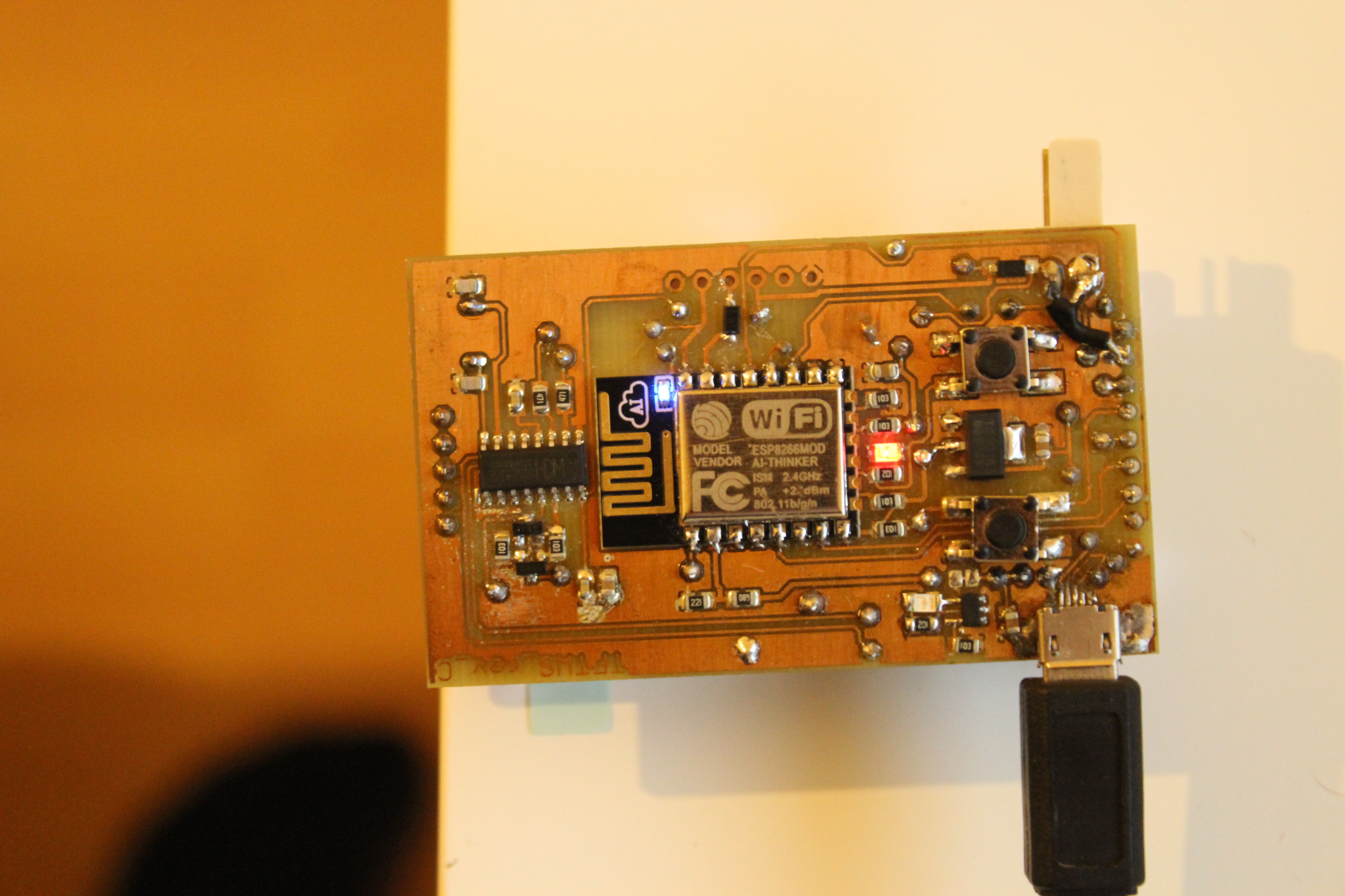
Here is how board look when is populated. Both previous revision have wire connections, this board is double sided becuase it would be to many wire connections.
I assembled board in this manner:
- I placed solder paste on pads which will be populated with SMD parts (resistors, capacitors, LEDs, buttons, ICs, etc.)
- I placed all SMD components on the board and run it through the reflow owen
- I checked all components for shorts after reflowing
- I checked voltage on pads where should be 3.3V and I found out that half of the board is without power
- Made test with continuity meater and find out that ground is not completely connected -> fixed problem with black wire in right low corner
- I soldered crystal for USB to serial chip and tested if PC will recognize it -> PASSED
- I soldered ESP12E and tryed programm it with USB -> NOT PASSED
- I tryed to programm it with flash button -> PASSED
- I soldered header for LCD and tested board with it -> PASSED
- I soldered header for battery and tryed to charge it -> PASSED
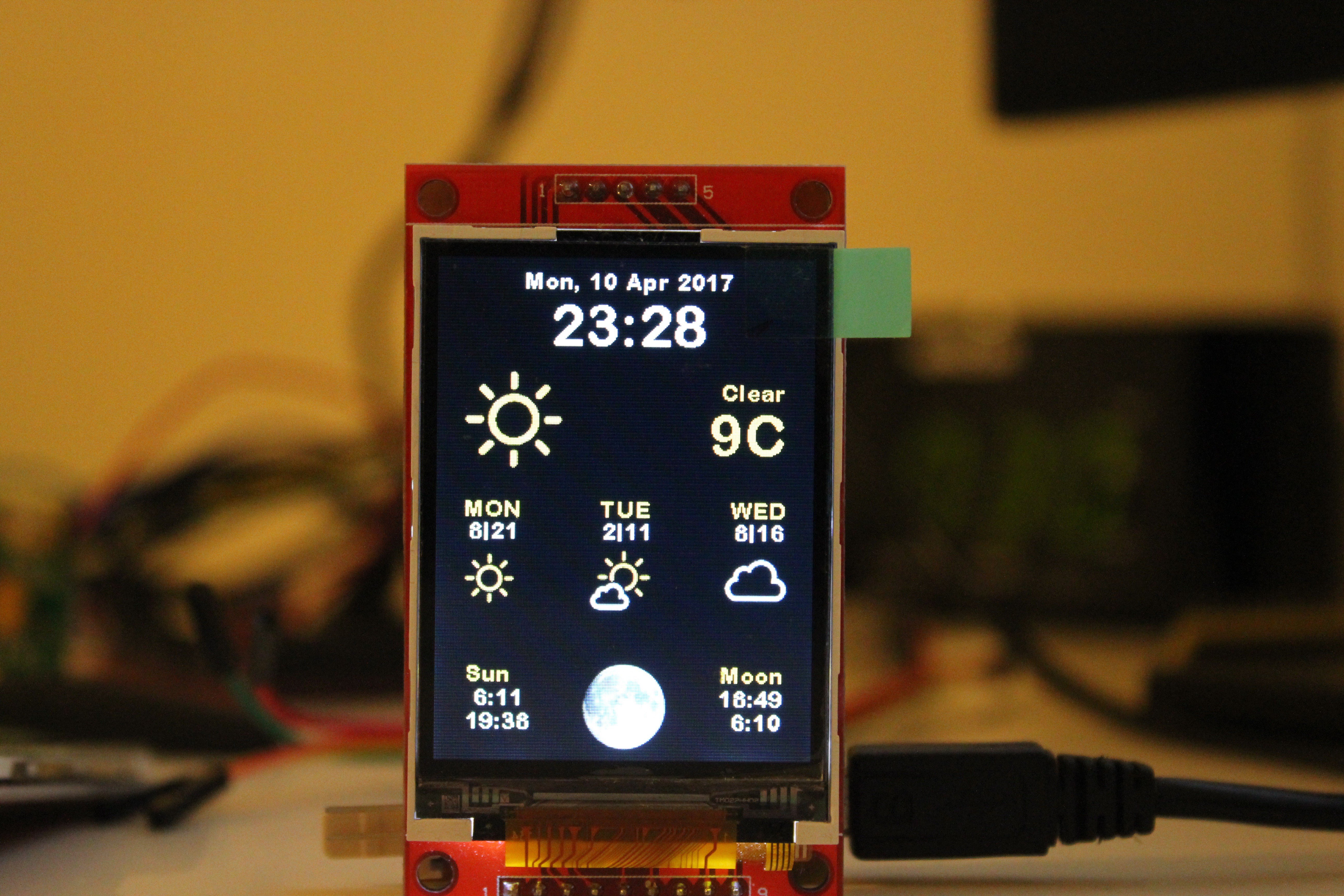
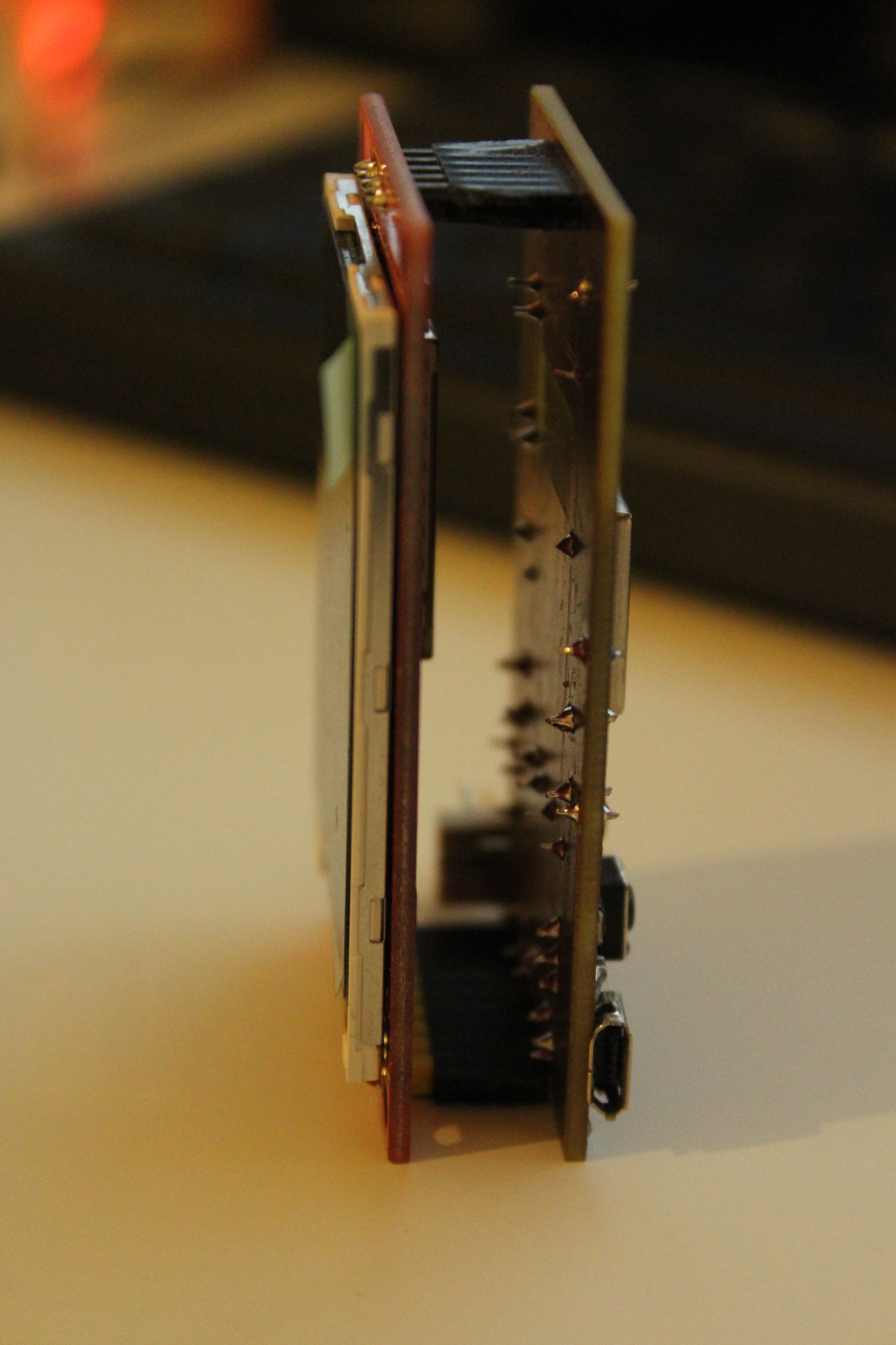
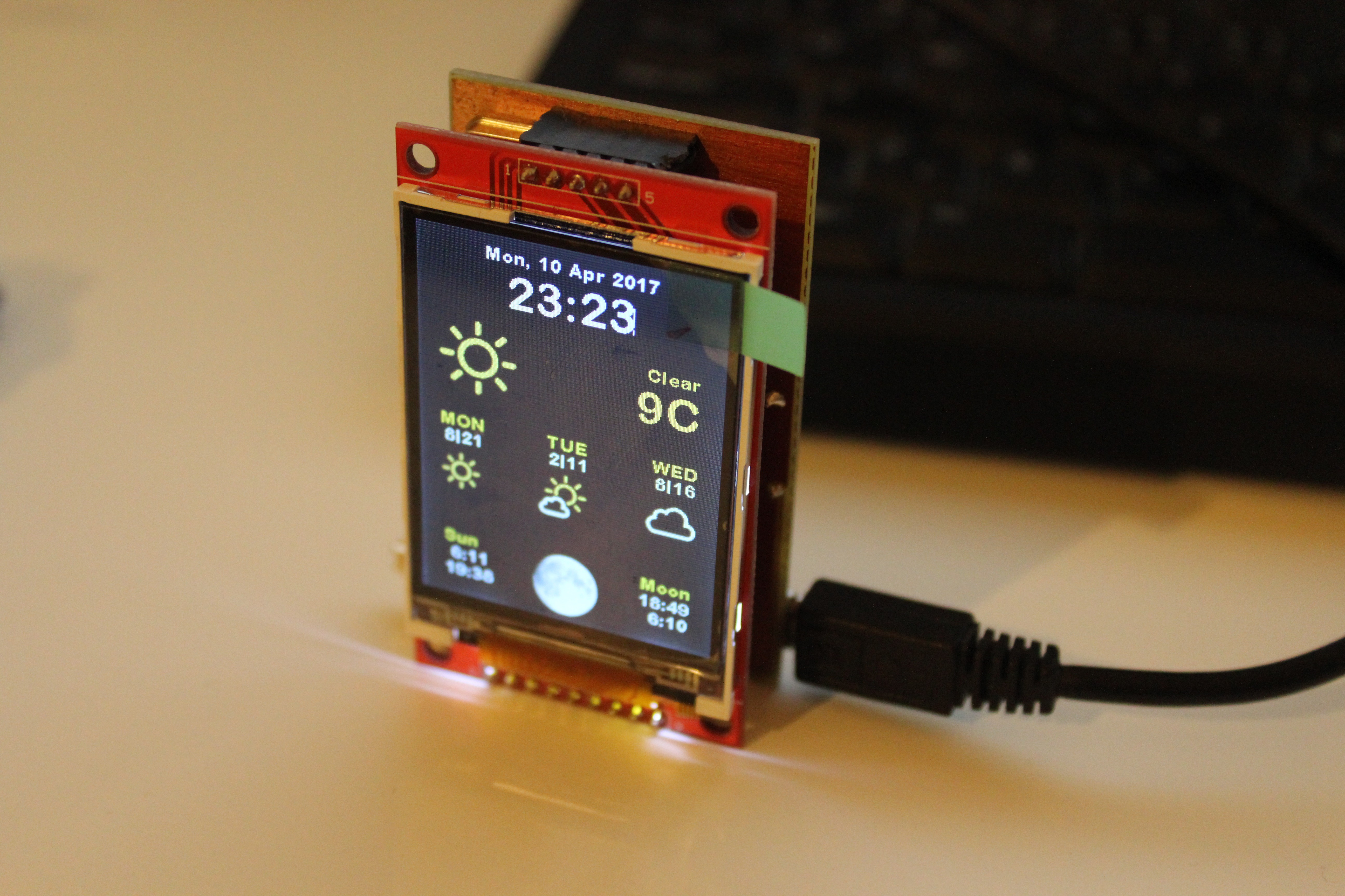
So far so good. Here is how fineshed board look like:
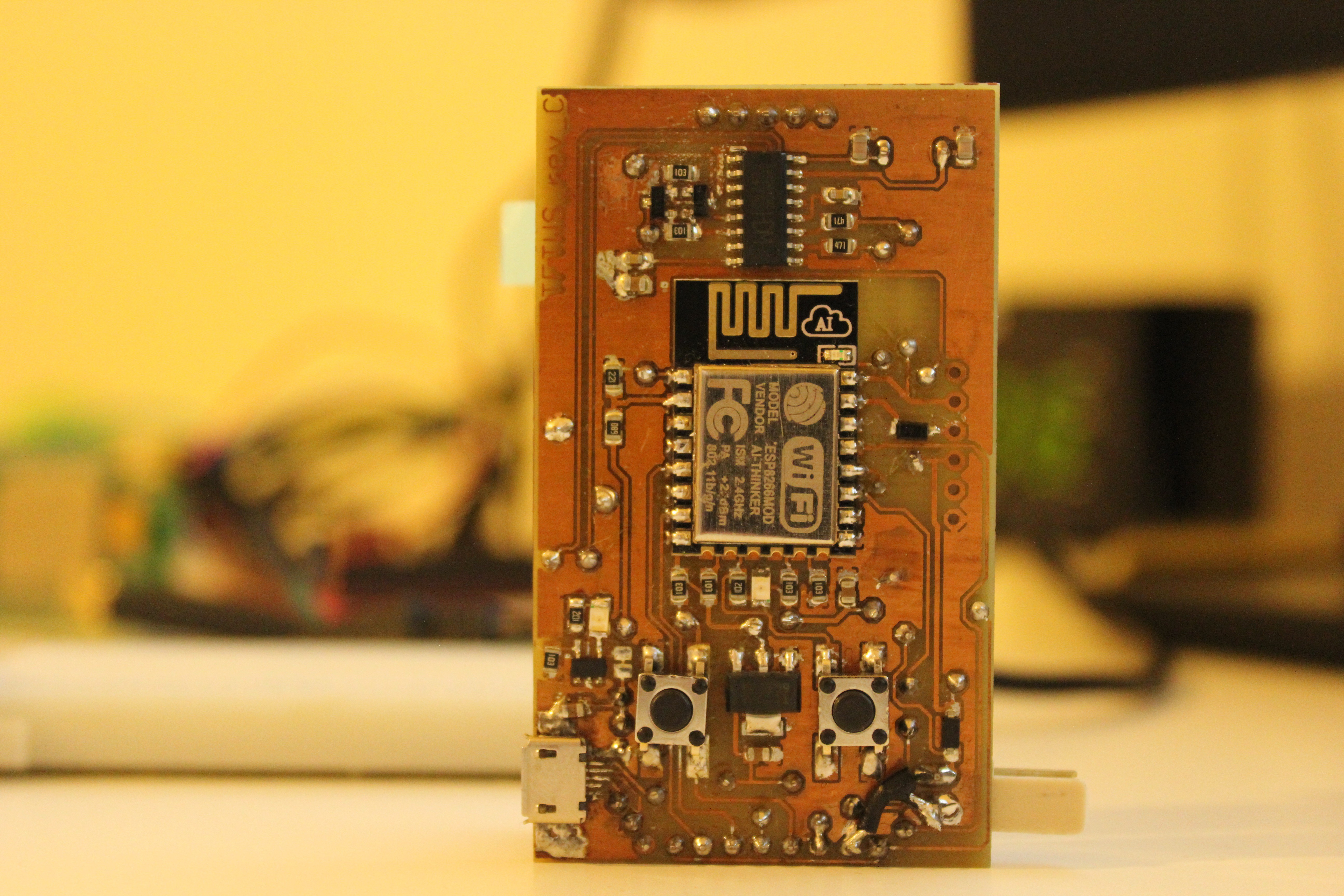
Ok, board is working, but is everything OK? No.
- I found out that one transistor from auto reset circuit was not centered enough on pads and it was not working, thats why auto-reset did not work. I desoldered it and solder in right way and that fixed this problem. Next try of programming through USB fineshed without problem.
- When battery is connected and charging is in progress, LED for charging should light up but it is not working -> I had no time to fix this yet.
- Battery power monitor is not working -> I measured voltage on analog pin of the ESP and there is something like 9V!! I was thinking why and after while a realized that I soldered wrong value of resistors on analog pin line. I placed 68R and 220R insted of 68K and 220K resistors. I had no time to fix this yet.
Here is more pictures of finished board:
Conclusion
Revision C board is finished and I think it is success. If I want simple board which will have same functions as orginal project from Squix78 and Ruiz Brothers it would be done, but so far I completed 3 from 7 tasks.
Thanks for your time with my project and that´s all for this revision, if you have any question, let me know in discussion ;-).
Discussions
Become a Hackaday.io Member
Create an account to leave a comment. Already have an account? Log In.