 Miroslav Zuzelka
In my first revision I decided to go easy at first, so I made simple board which will contain these components:
- ESP12E
- 3.3V voltage regulator LM1117
- Reset button
- Flash button
- FTDI connector
- LCD connector
- Some resistors
- Some capacitors
- LED for flash state
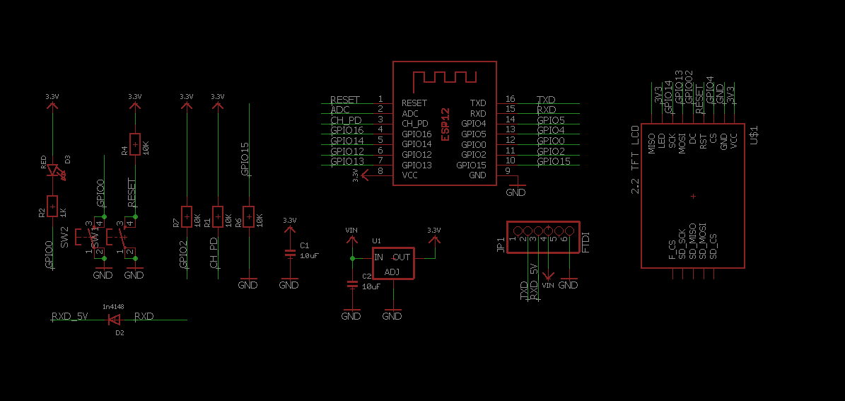
I draw everything in Eagle and schematic looks like this:
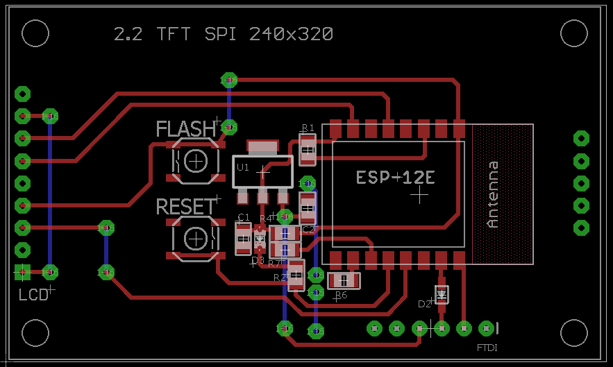
Then I placed all parts where I thoughed will be appropriate :
After that I send my design to one of my friend which make PCB here in Czech Republic (www.plosnaky.cz) , waited for few days and pick one up. Sadly I have no picture before I start assembly of the board so here is how first board look like when I fineshed it.
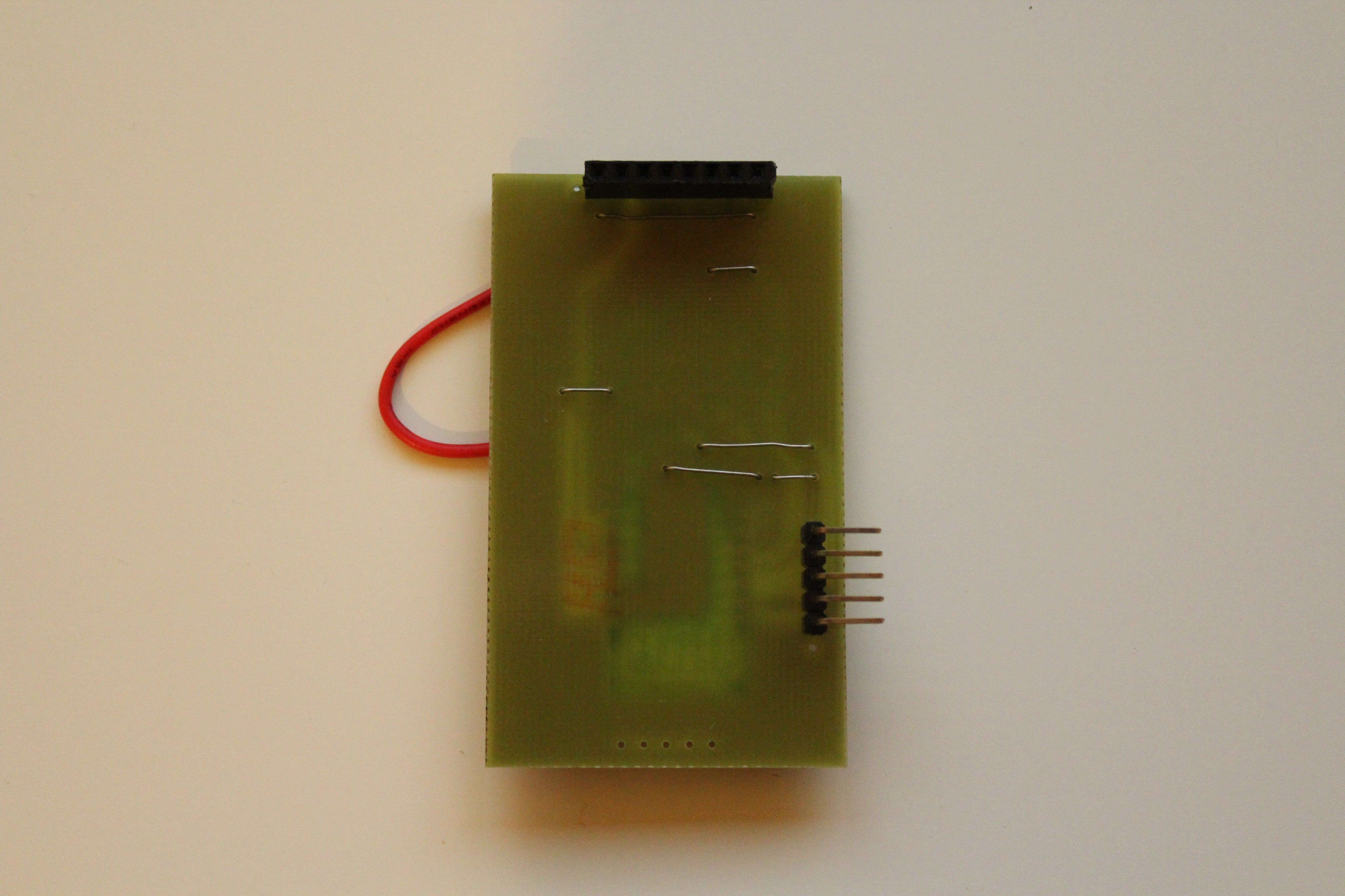
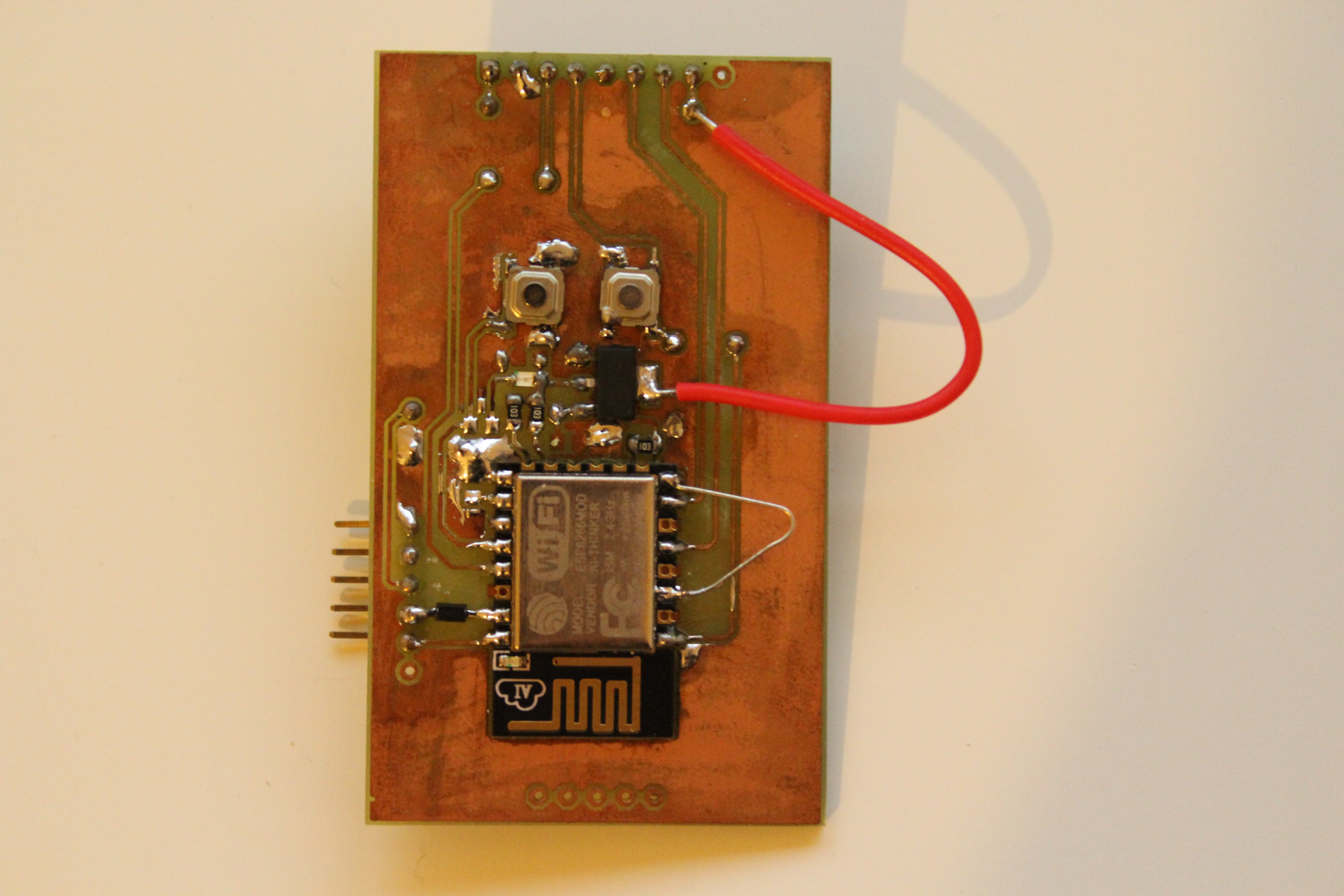
This board take power from FTDI connection which you can see on left side of the board.
Discussions
Become a Hackaday.io Member
Create an account to leave a comment. Already have an account? Log In.