JohSchneider
-
MK2: final assembly
01/11/2024 at 17:57 • 0 commentsThis one is meant as "split, but monoblock" - with the MCU and two halves screwed down do a small board
![]()
untreated laminated wood: good surface grip = ideal for "literal laptop" use
another option is to keep the halves separate, for a "desktop use"where it is beneficial to slide them around for a relaxed/straight wrist position
-
MK2: (hand)soldering
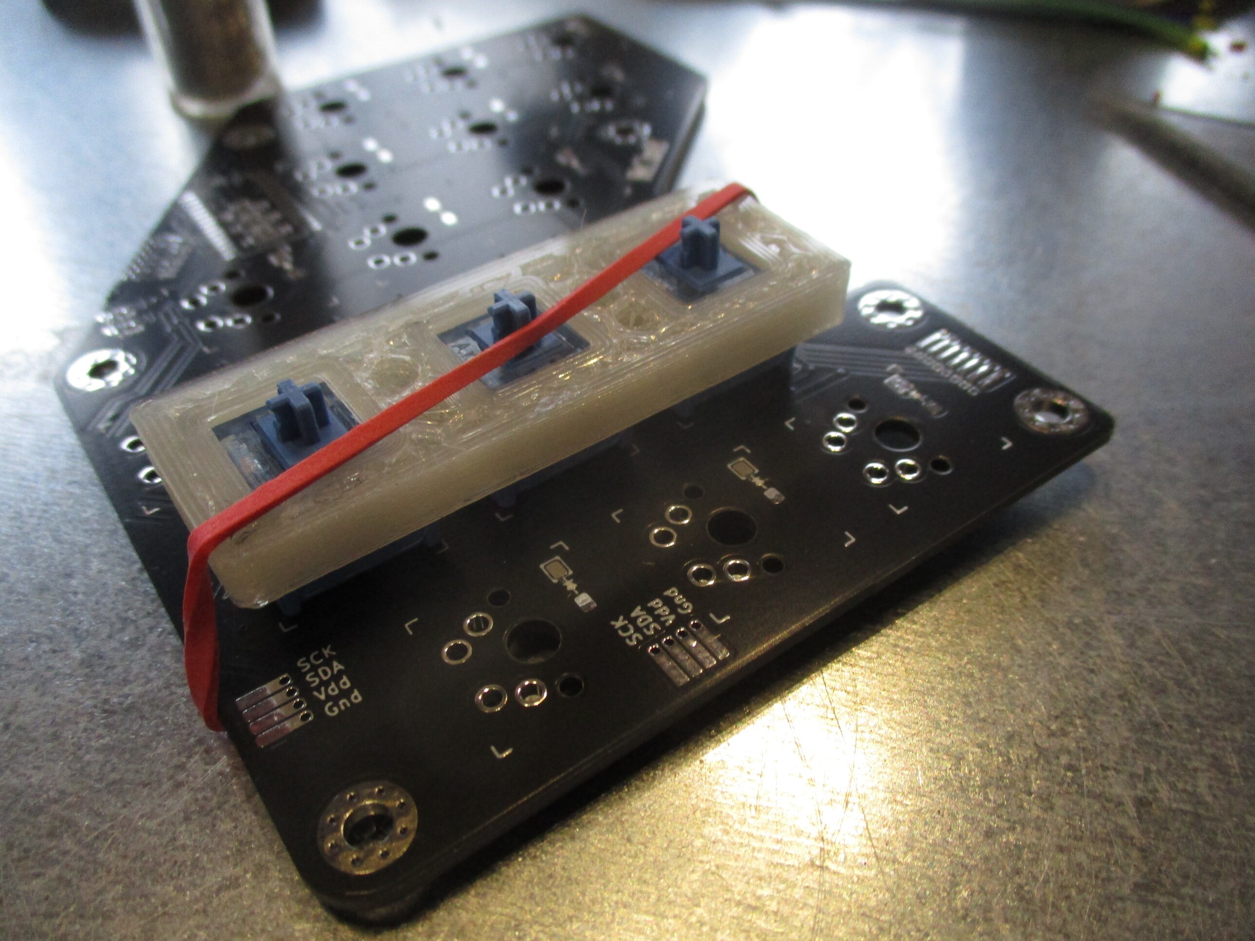
01/11/2024 at 17:50 • 0 commentsthe pcb is straight forward
- smd diodes: according to their markings, bottom side
- io-expander: only one per pcb, bottom or top
- switches: in triplets, aligned with the help of a small jig
![]()
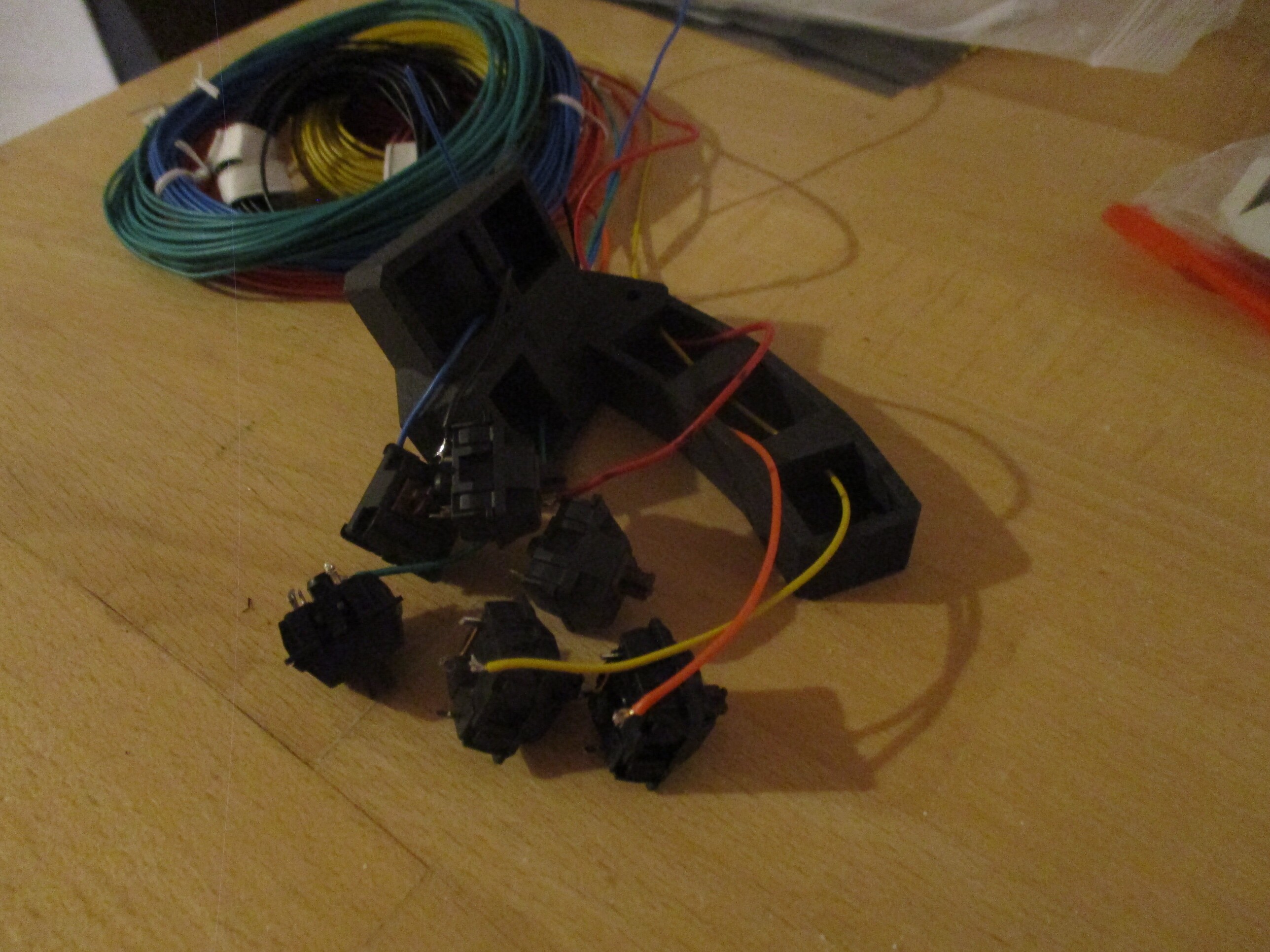
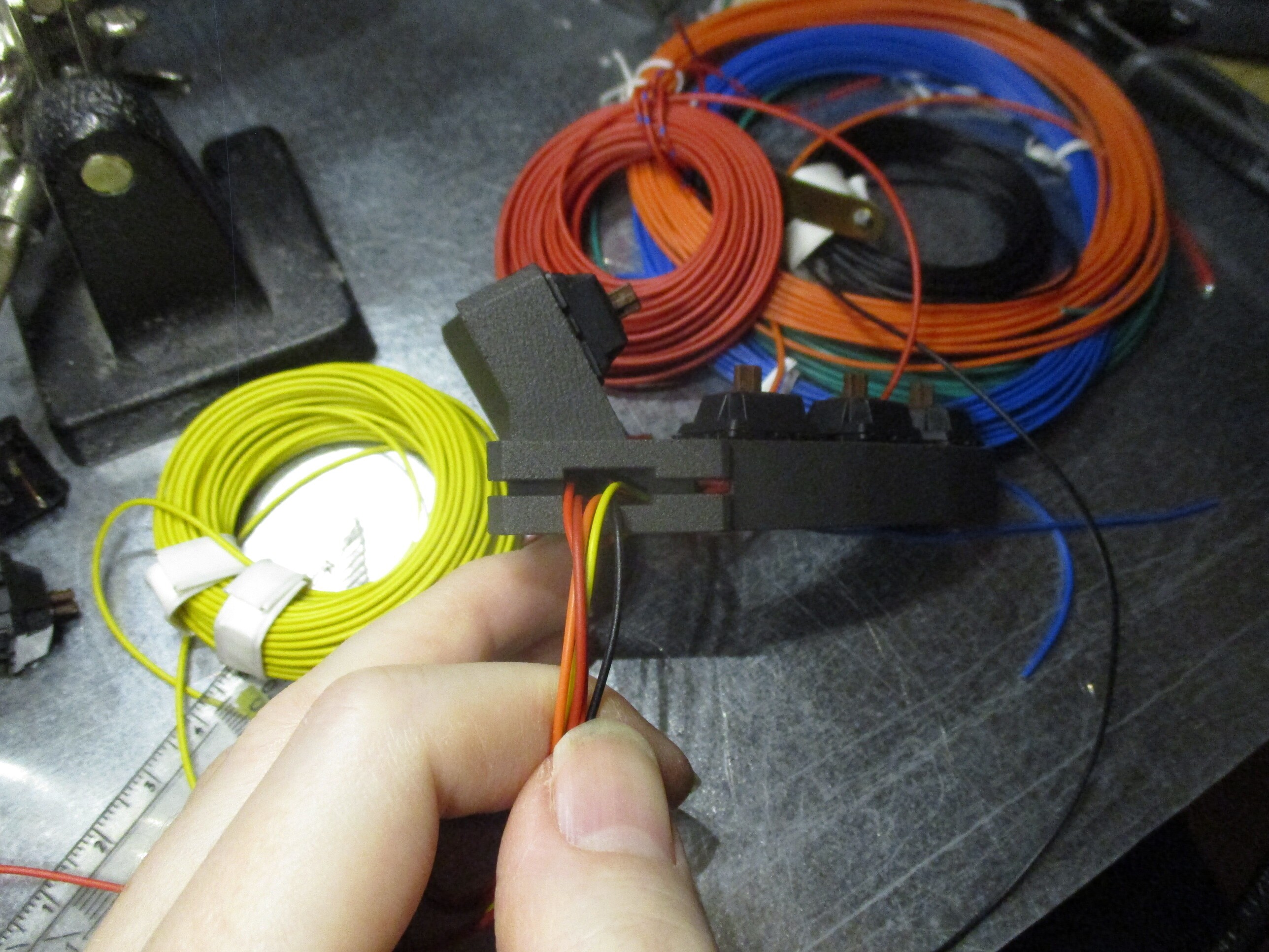
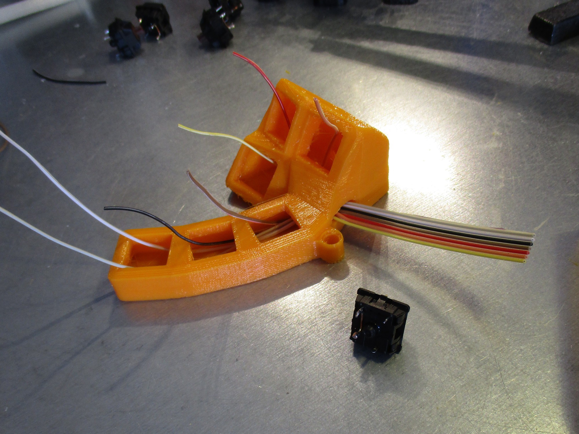
the thumbcluster is a little more effort :-)
1. the printed part has M3 screw holes, which need to be tapped
2. each switch is prepared with a THT diode
3. each switch gets it's own "column" wire, threaded through the PCB slot
![]()
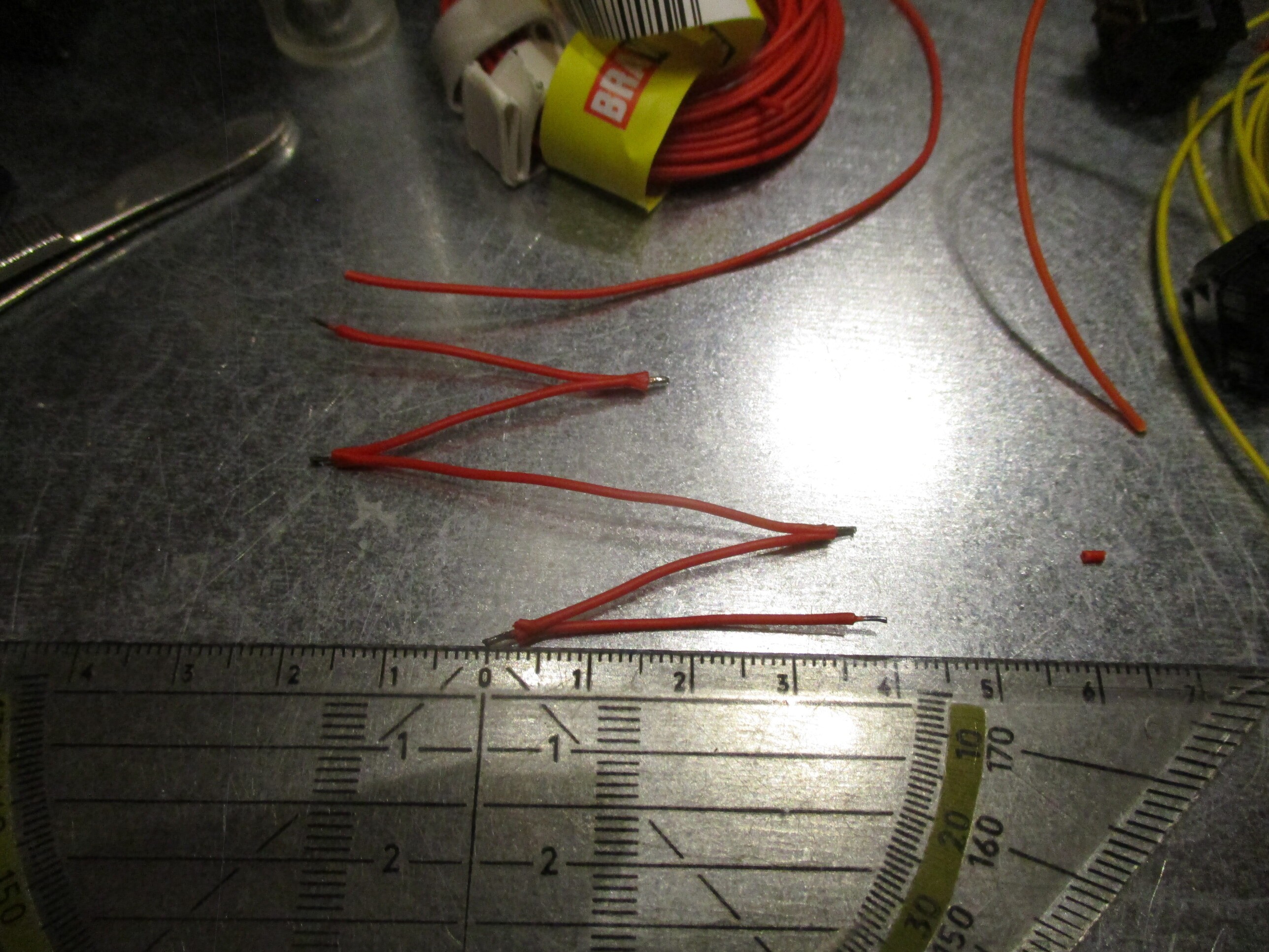
4. the "row" wire is prepared: 4cm+4cm+6cm+4cm+4cm+spool
![]()
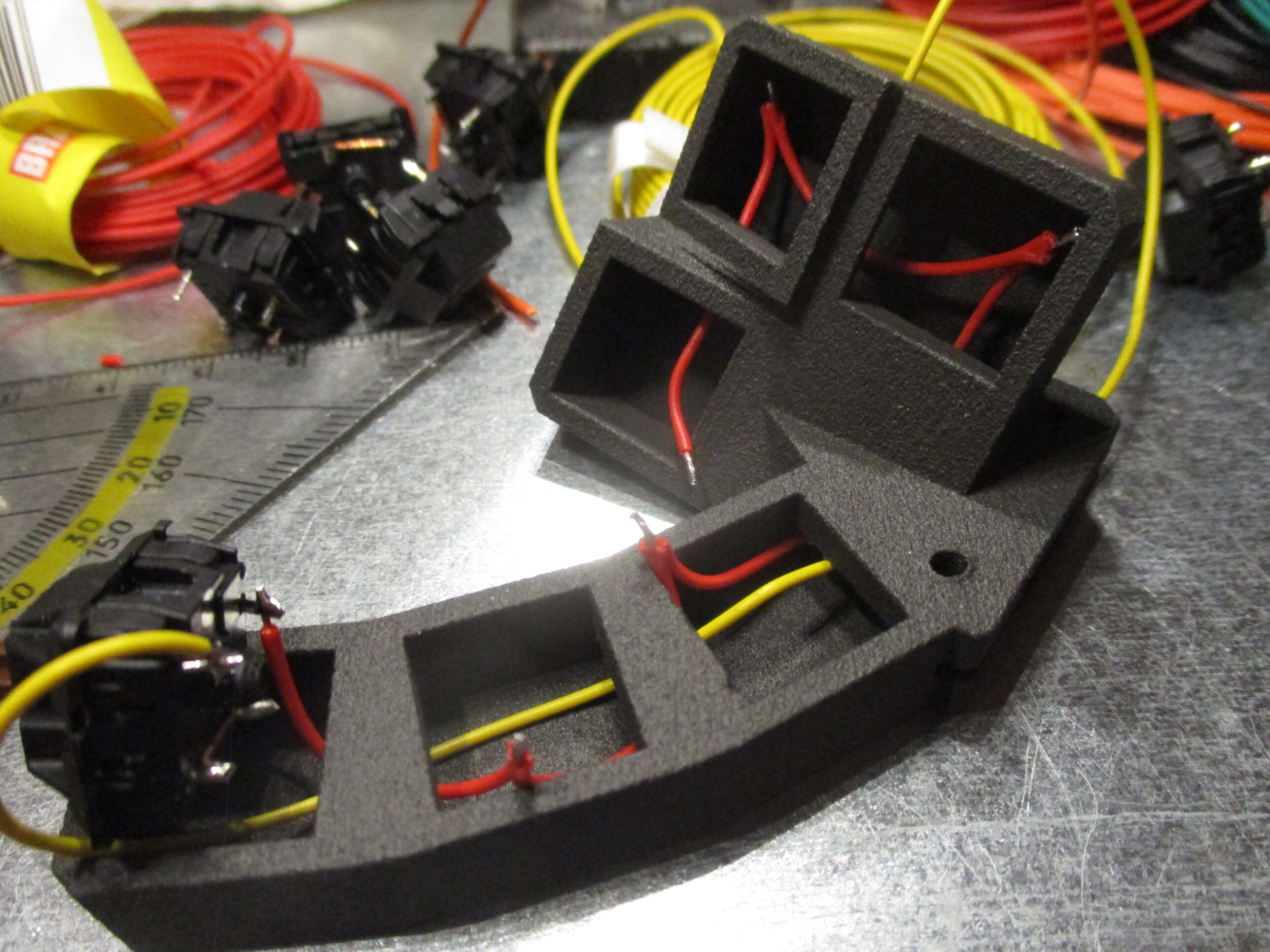
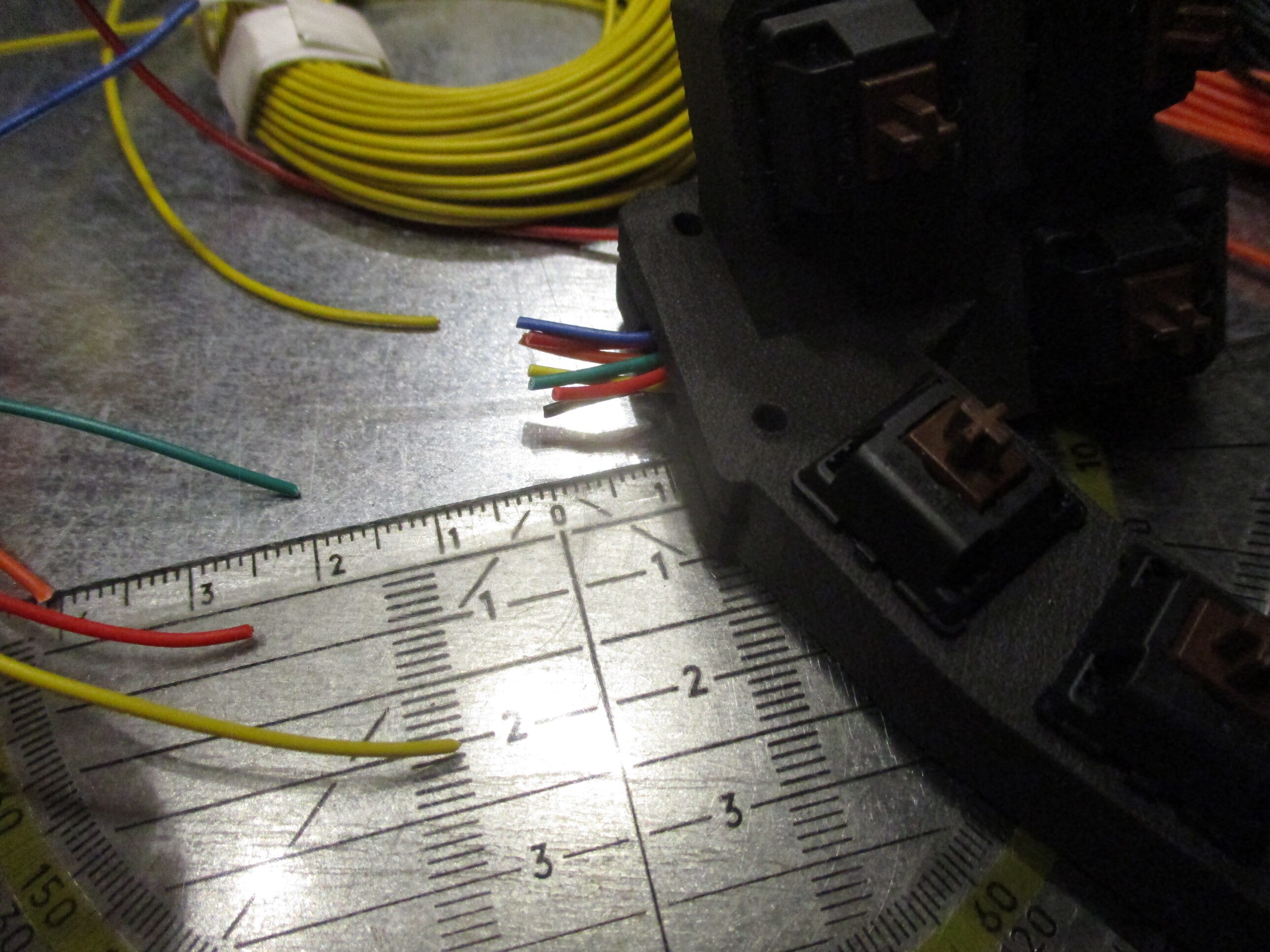
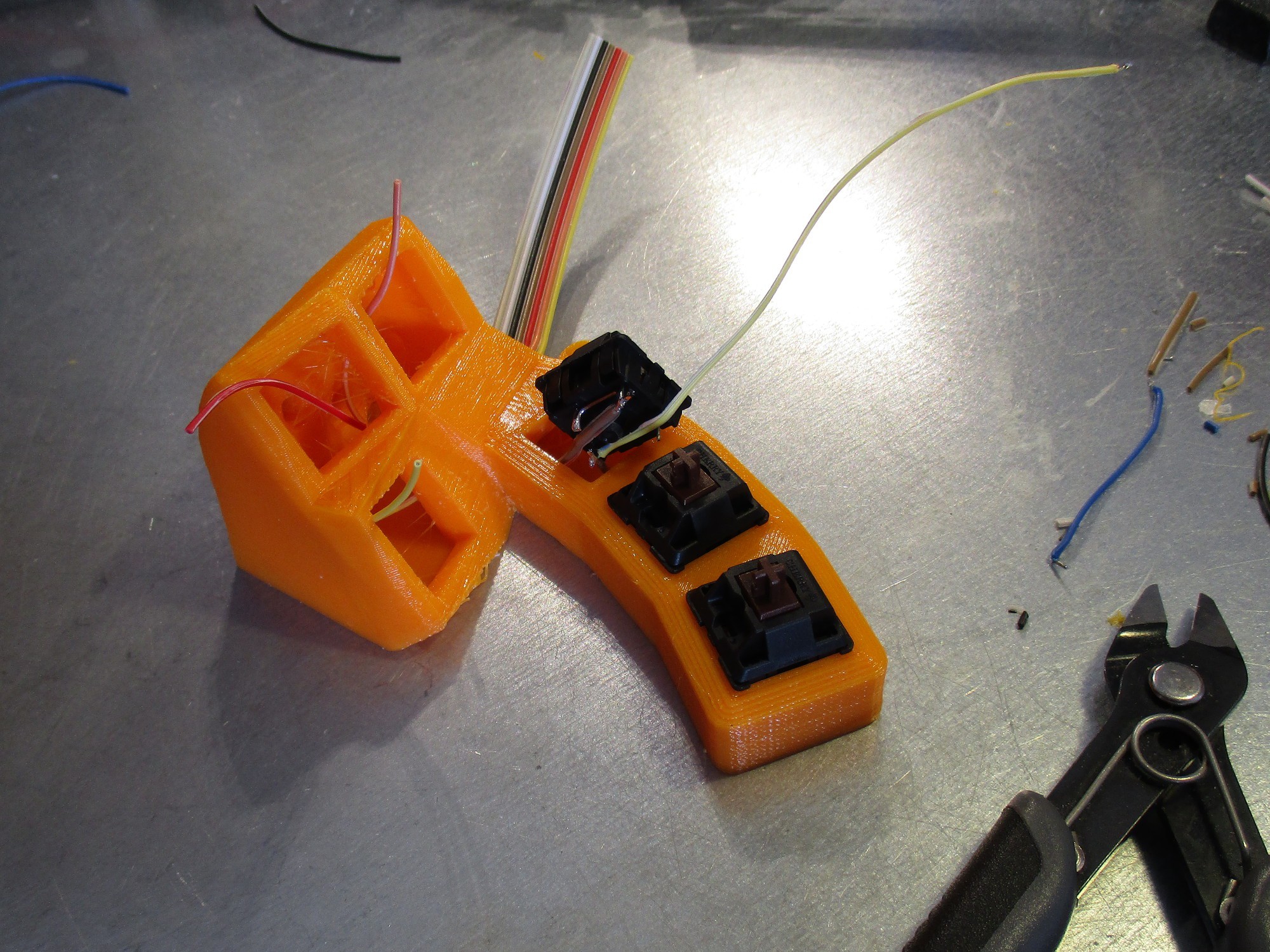
5. threaded through and soldered to the switches
![]()
6. the wires are cut to length, checked that they run all through the central hole (and not any small adjacent ones) and stripped
![]()
![]()
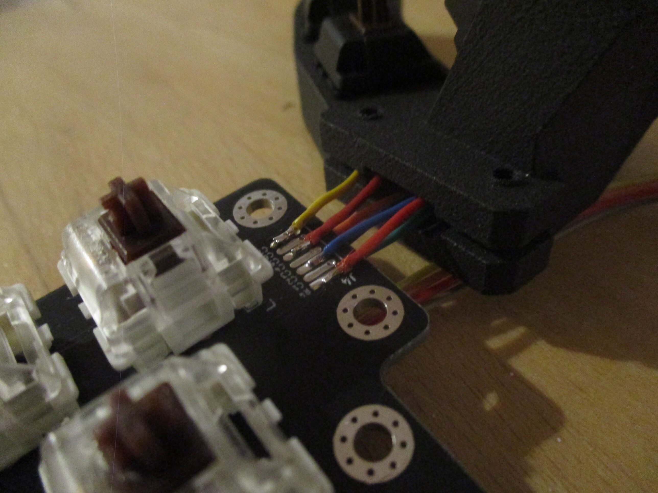
7. connecting to the pcb:
since the pads are available on both sides, and spaced for a ribbon cable, alternating between front and back
![]()
![]()
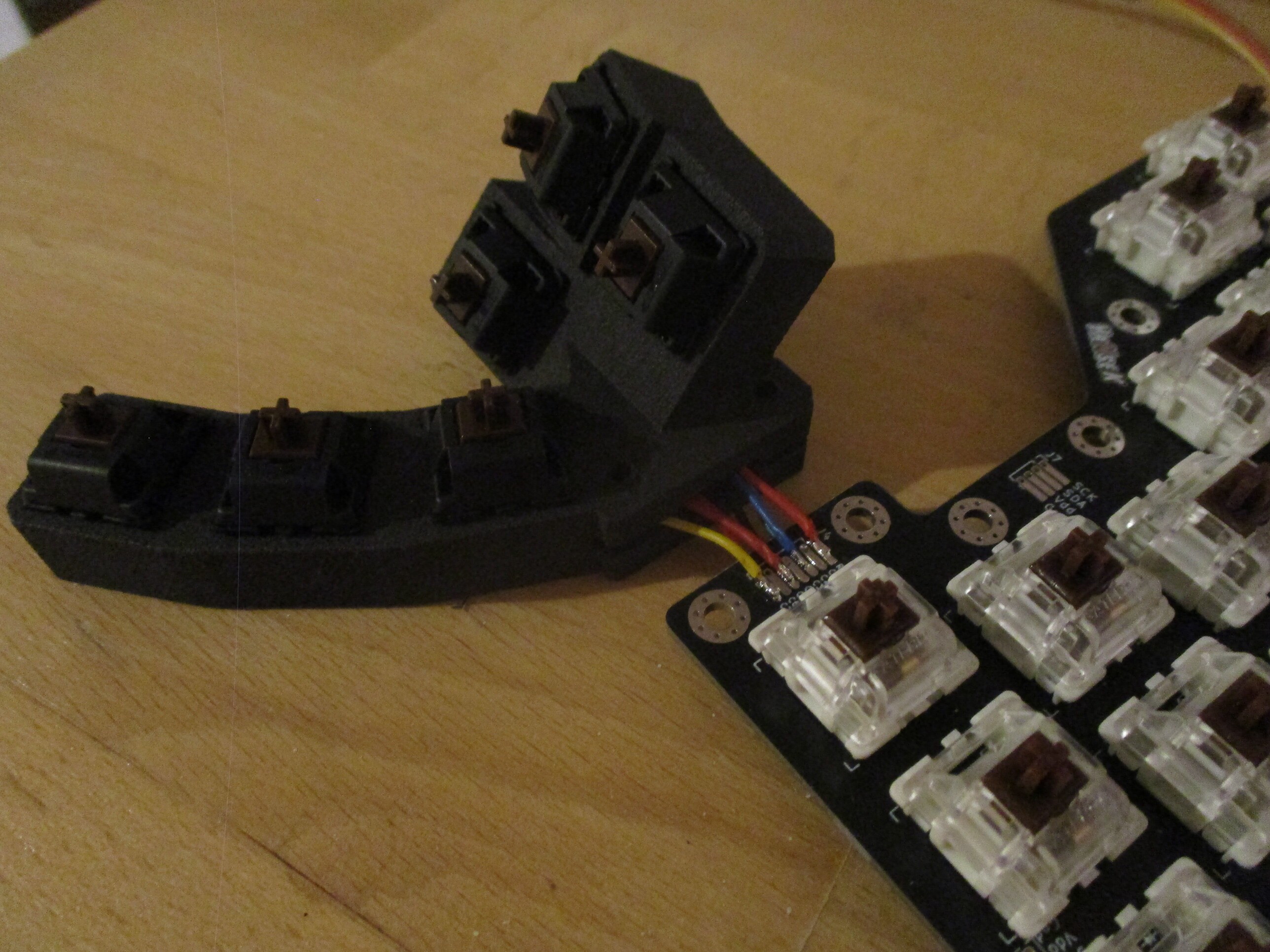
Note on the column order, and color coding:
chose *the same* color codes for the left and right assembly. since the pcb is flipped, so is the order
e.g. the left side has from left to right C0...C5; where as the right side has from left to right C5...C0
in the above picture, the leftmost key has a yellow wired, connects to C5 pad - and would do the exact same for the right side
-
MK2: making a case
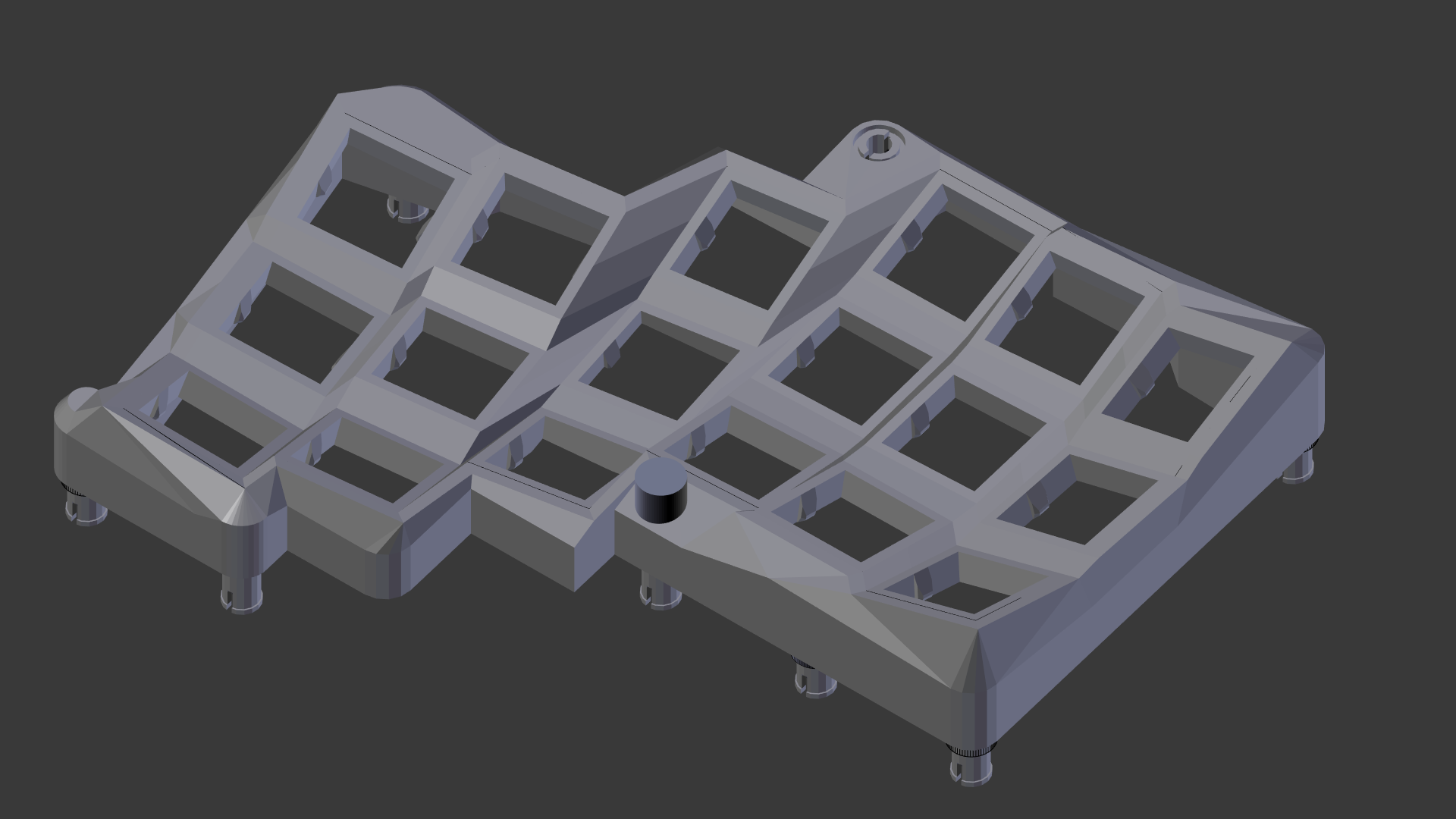
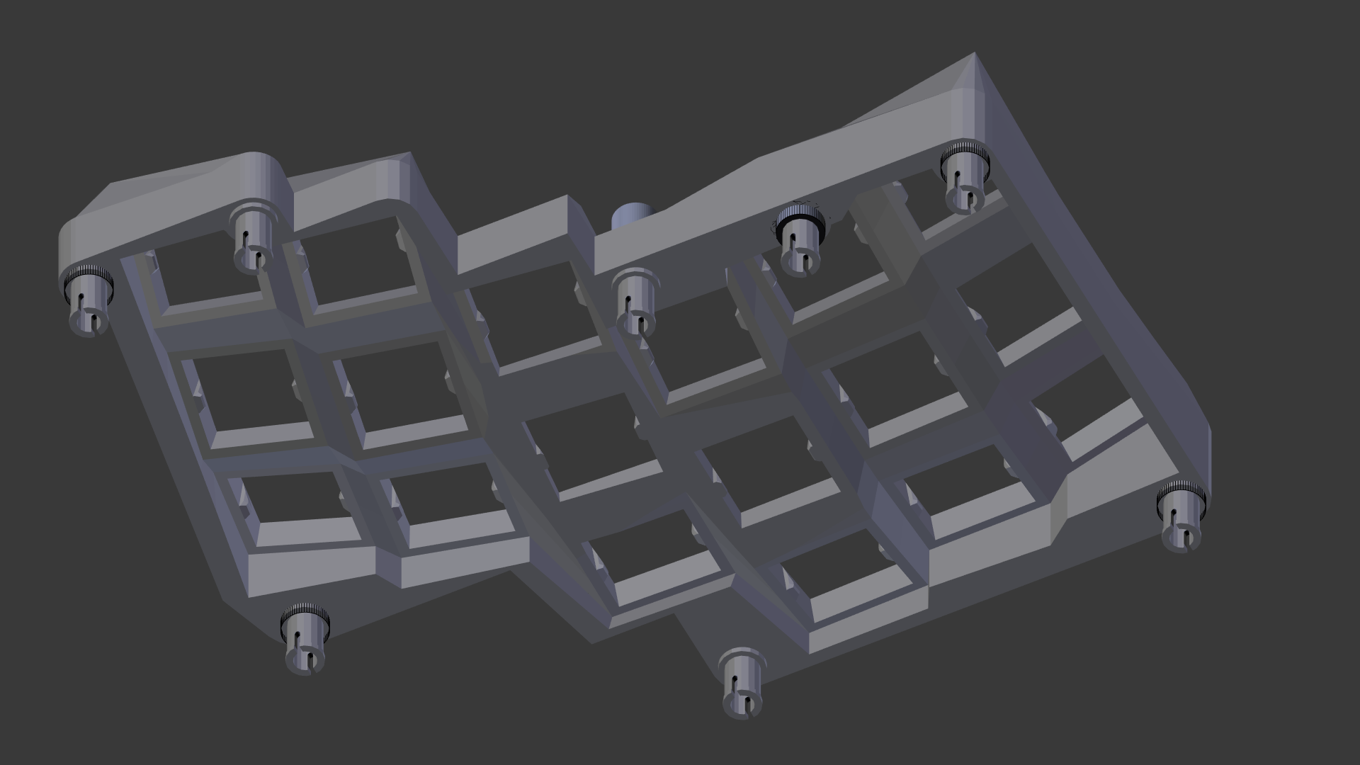
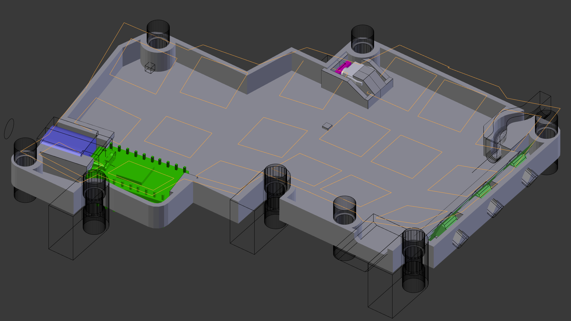
01/11/2024 at 12:24 • 0 commentssome more time in... blender:
![]()
which is the
- thumbcluster, that has to be handwired, and has a slot for the PCB
- top and bottom shell
- and a holder to mount a Cirque trackpad to (the 40mm variants)
-
MK2: pcb-in'
01/11/2024 at 12:07 • 0 comments -
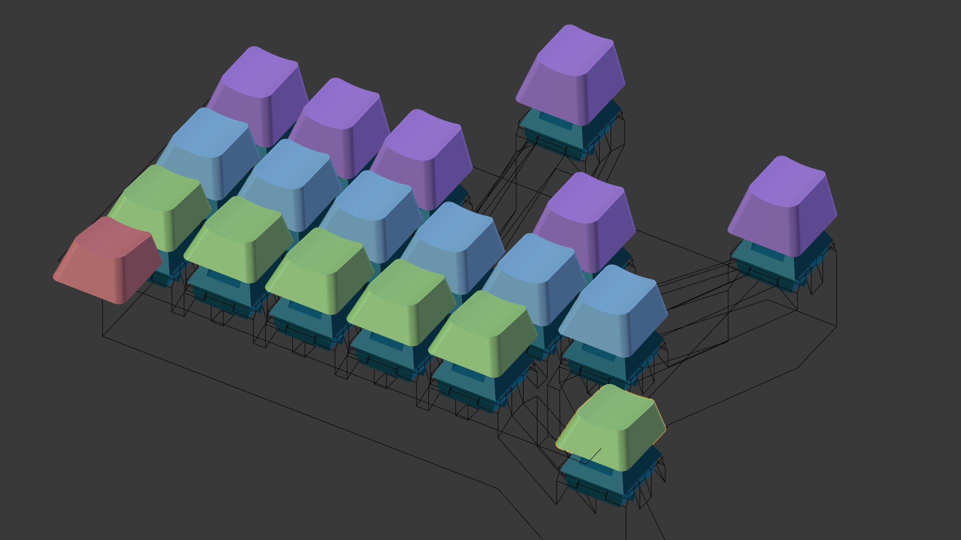
MK2 begins: layouting a pcb
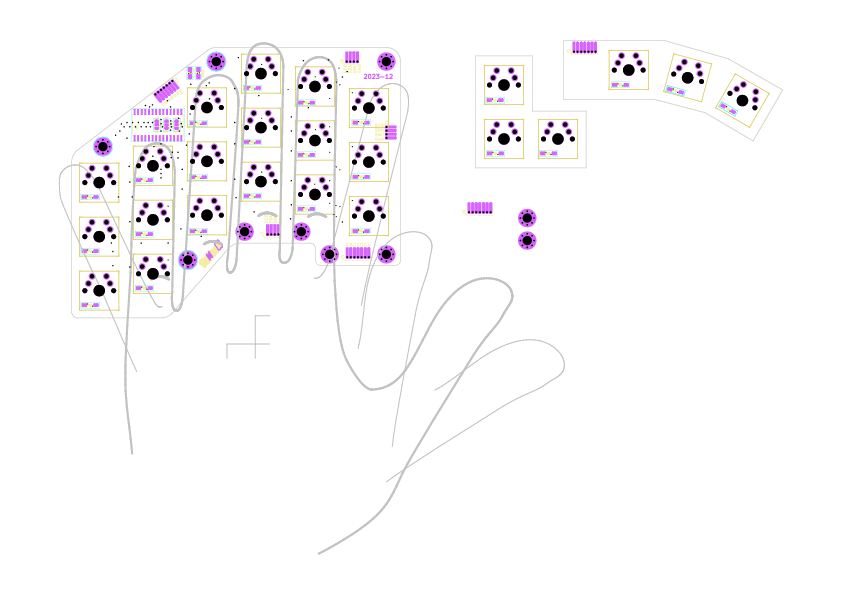
01/11/2024 at 11:18 • 0 comments![]()
a new iteration starts with an idea: have a PCB that replaces most of the handwiring
first task: figure out the (now 2D :-( ) switch positionsto get there the outline of one hand is traced on paper, digitized and pulled into kicad as user-drawing
then (after creating the matrix schematic) the switches are positioned in relation to that outline.
the pcb-cut border can also be drawn up, to have an idea how/where to place the thumbcluster later on. -
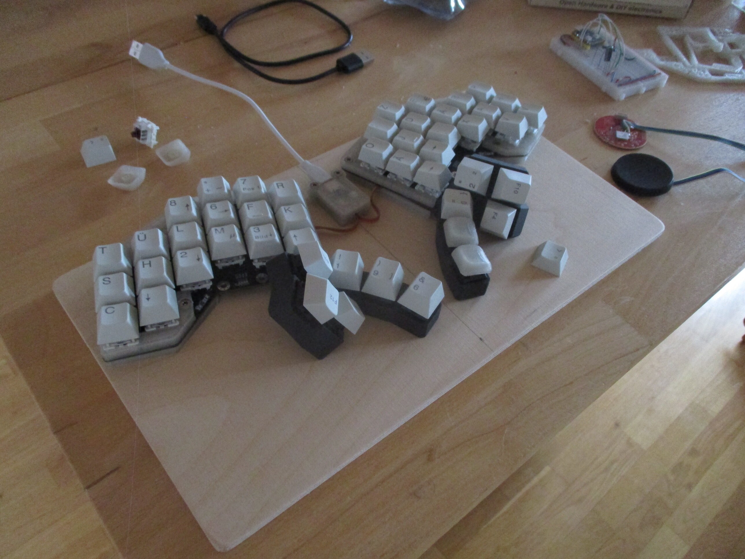
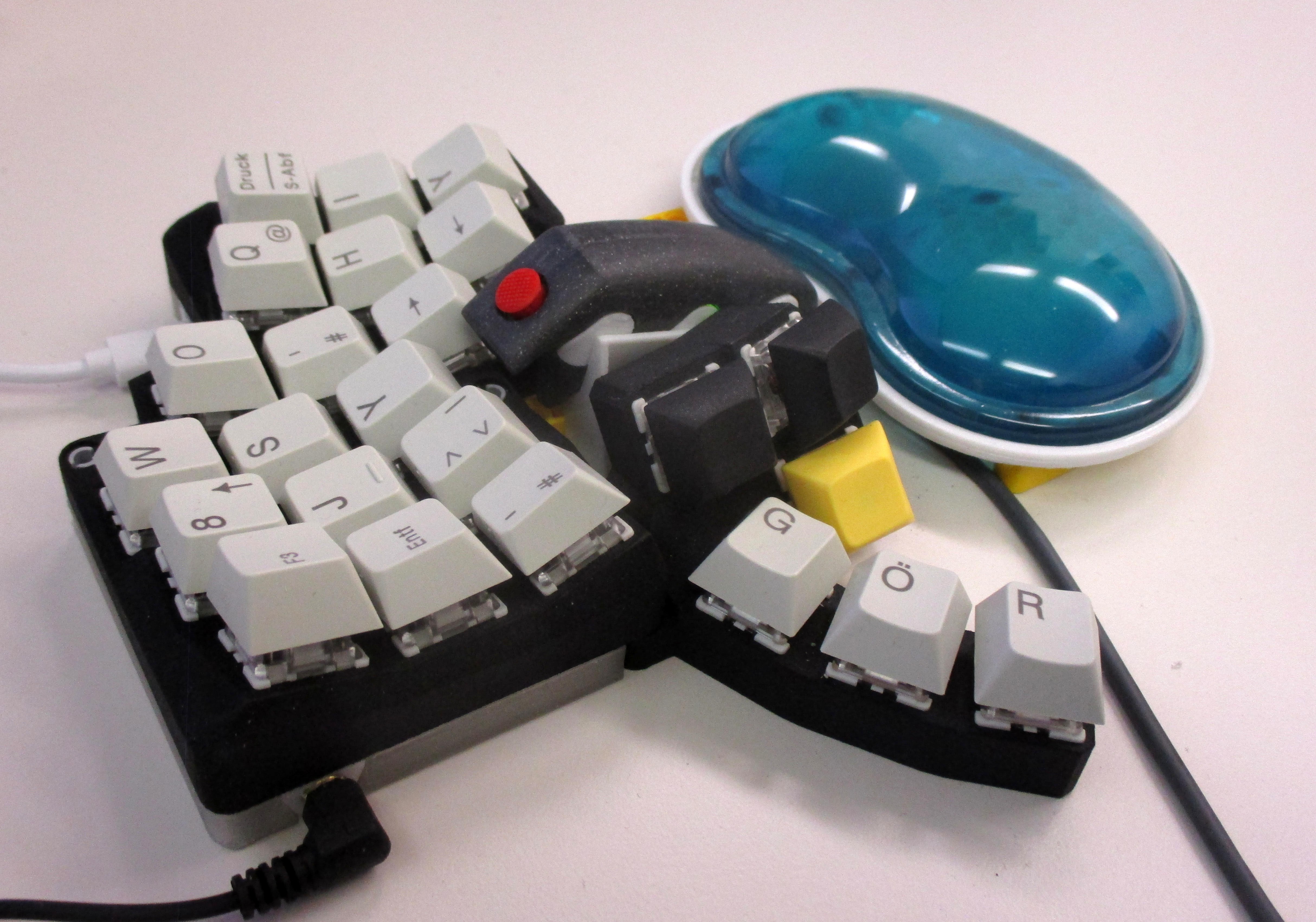
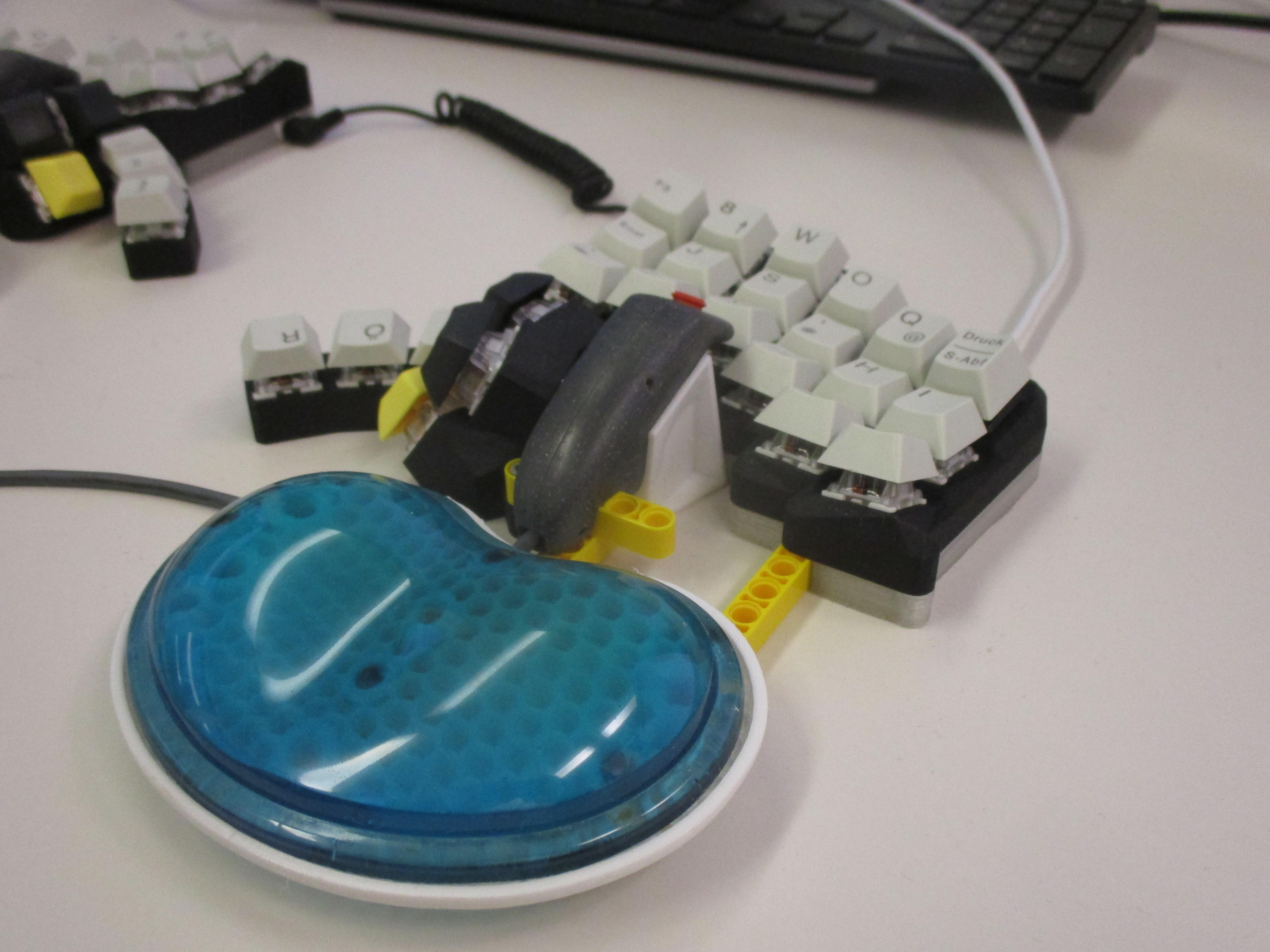
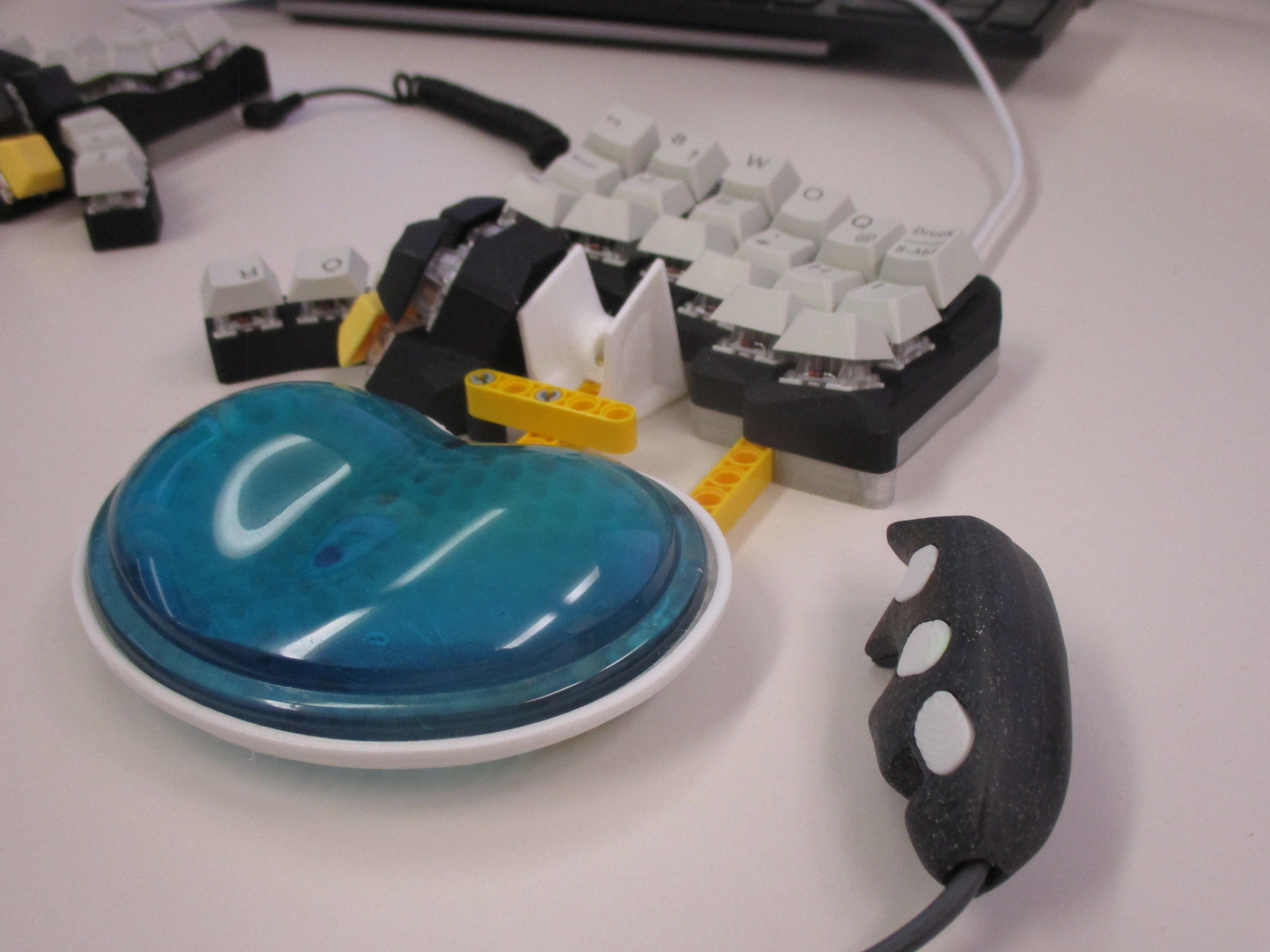
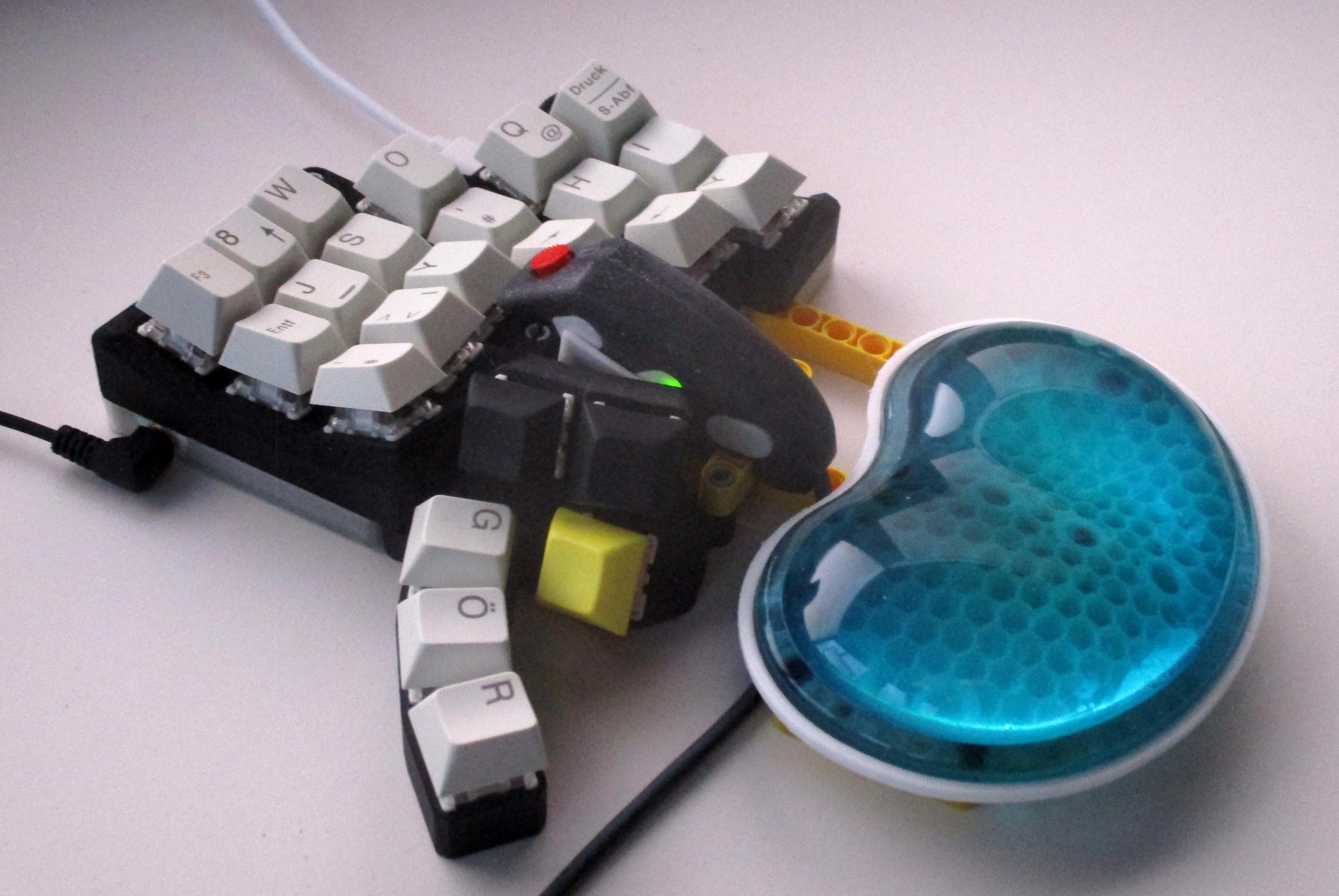
2OAK materializes
10/03/2022 at 14:09 • 0 commentsdusting off an old project, to build a 2nd-of-a-kind for the workplace/office.
using the opportunity to bring the firmware up-to-date with the current qmk repository, and even throwing in "vial" support
all the while using a new MCU to run the show: the currently en-vogue RP2040
with an added "module": a ibm-style trackpoint mouse
![]()
![]()
![]()
![]()
-
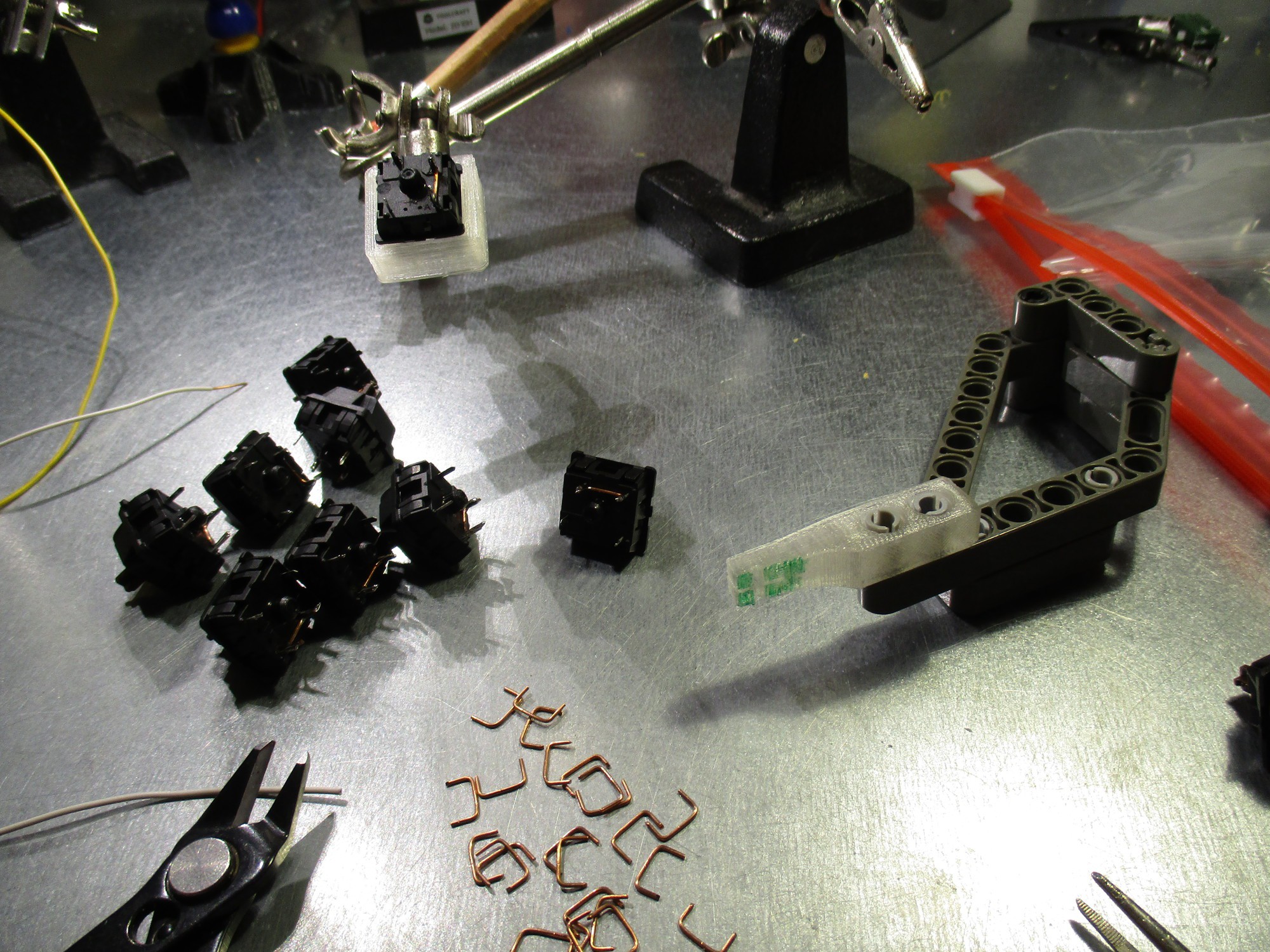
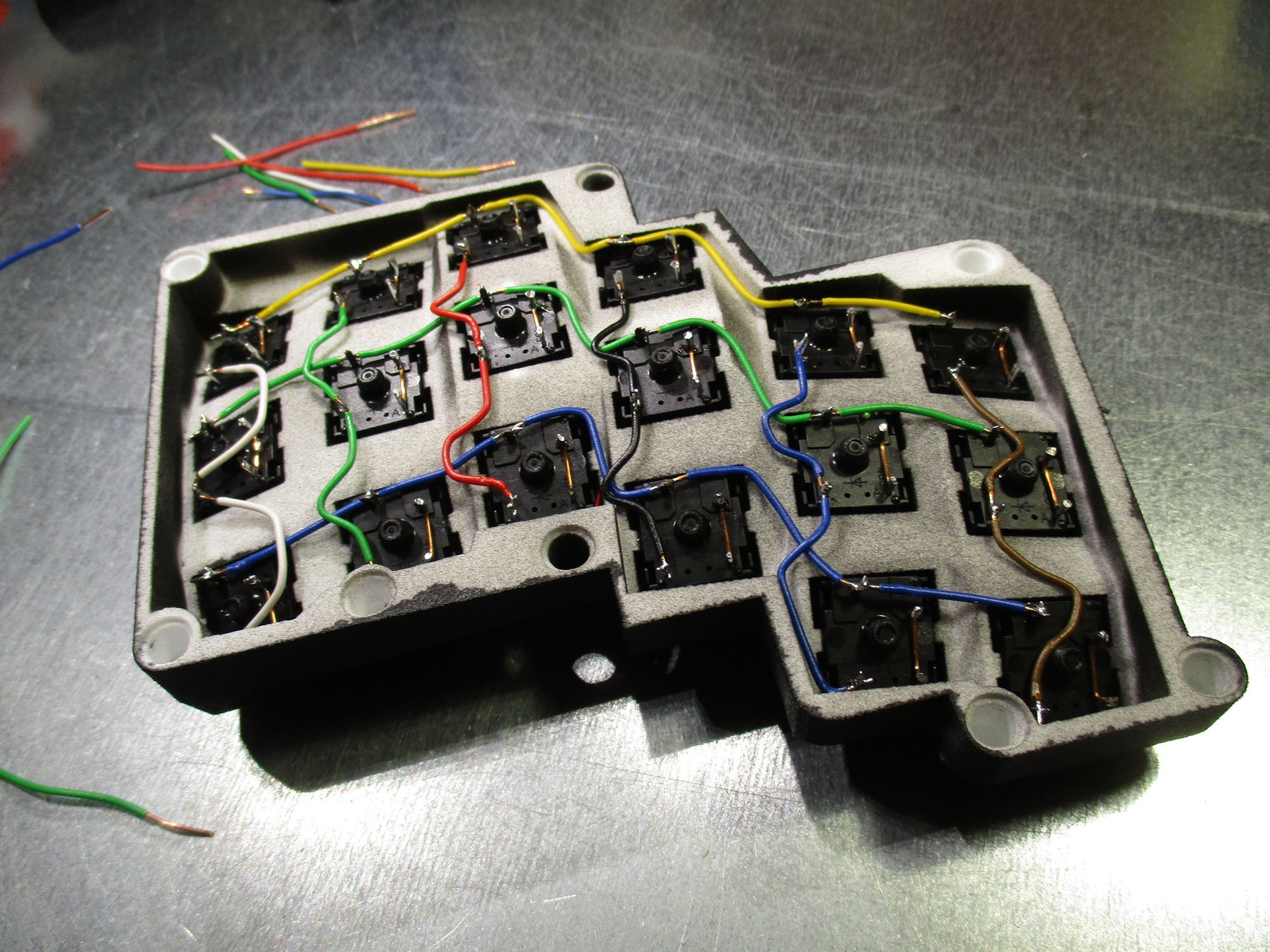
handwiring the Matrix
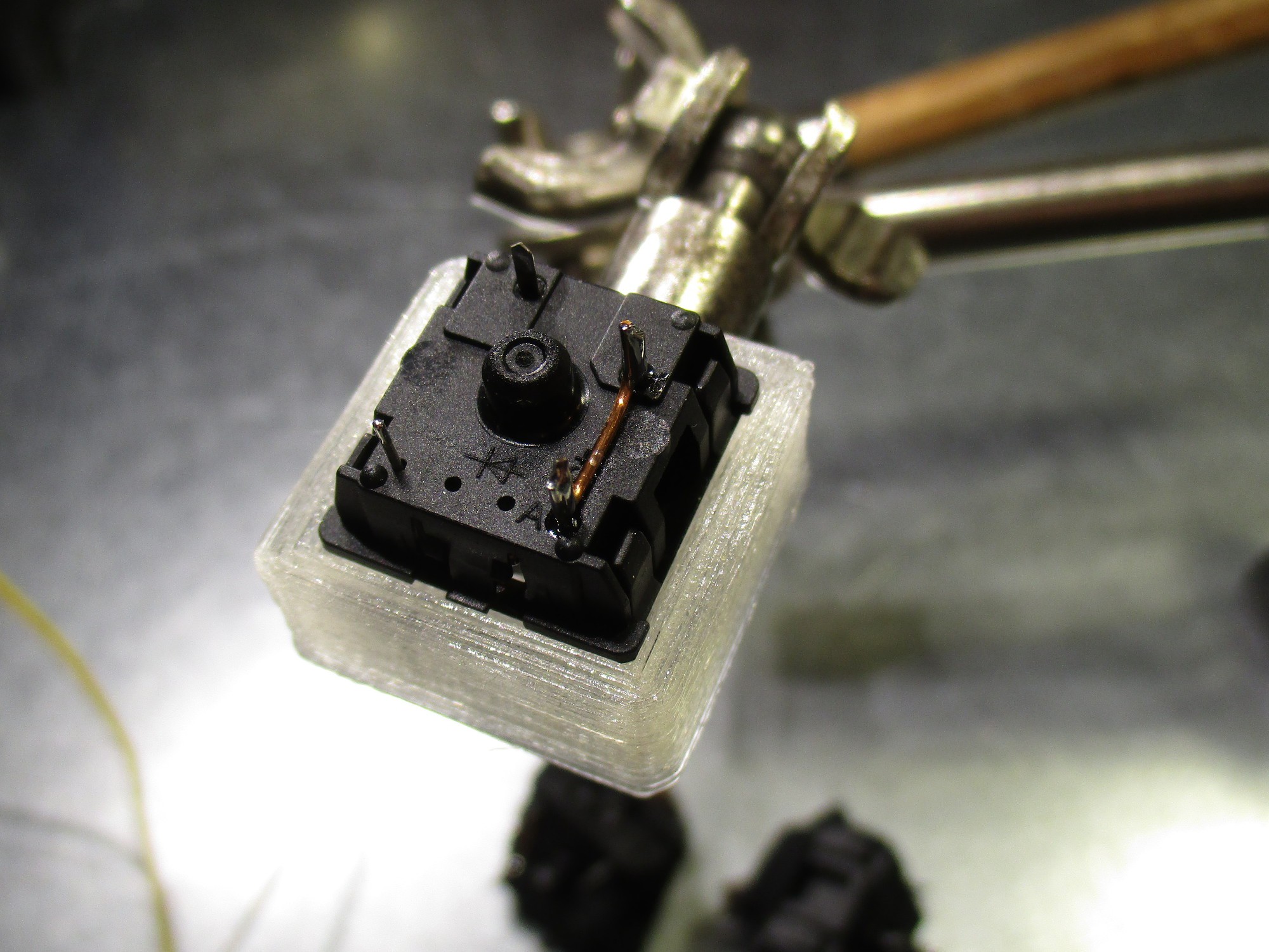
05/01/2017 at 18:35 • 0 commentssince the switches, scavenged from a cherry keyboard already had diodes installed, all that was needed was a small wire bridge - made with a small bending jig from solid-core wire
![]()
![]()
... the same wire which is used to connect the rows...
![]()
... and columns.
![]()
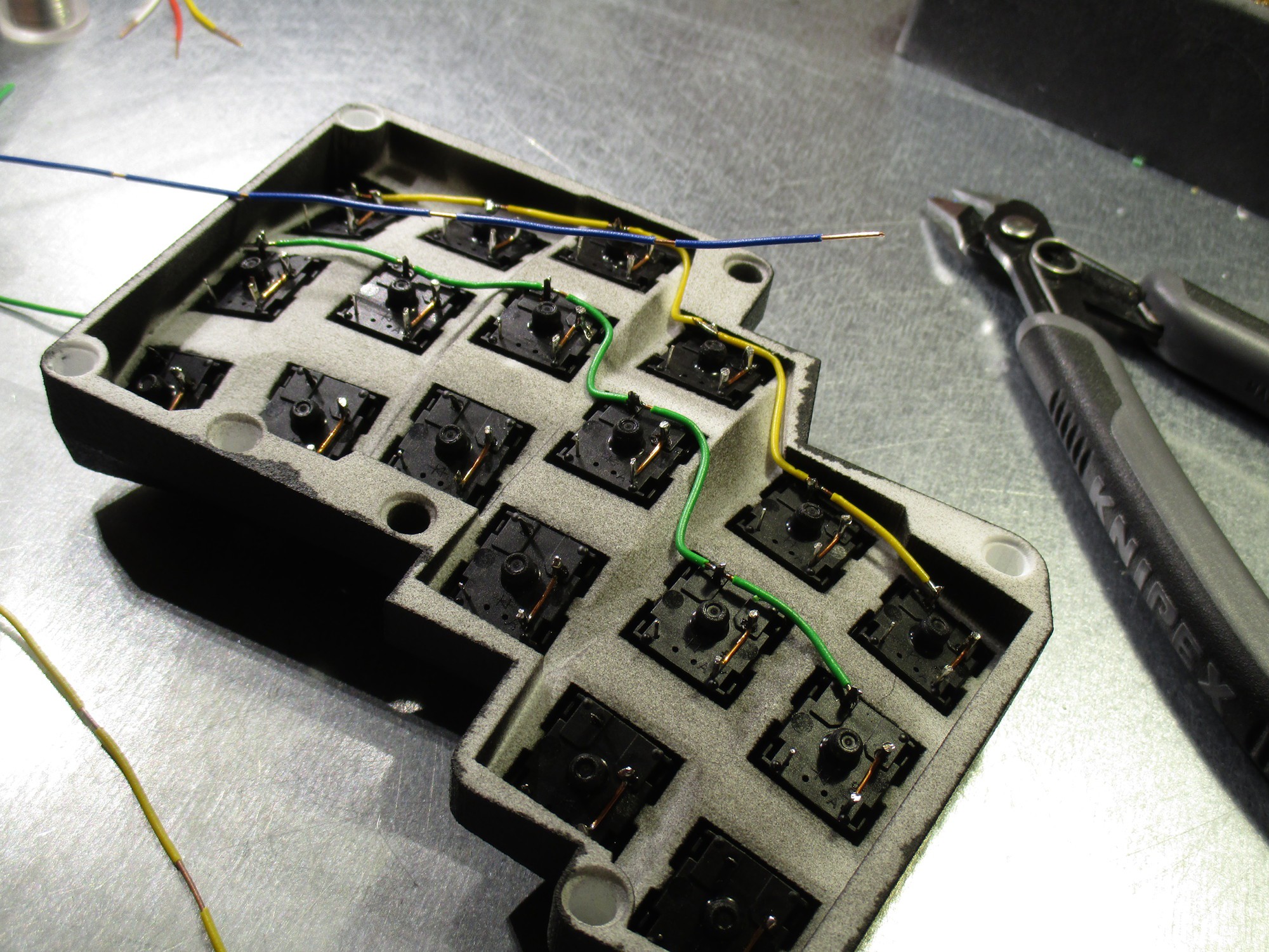
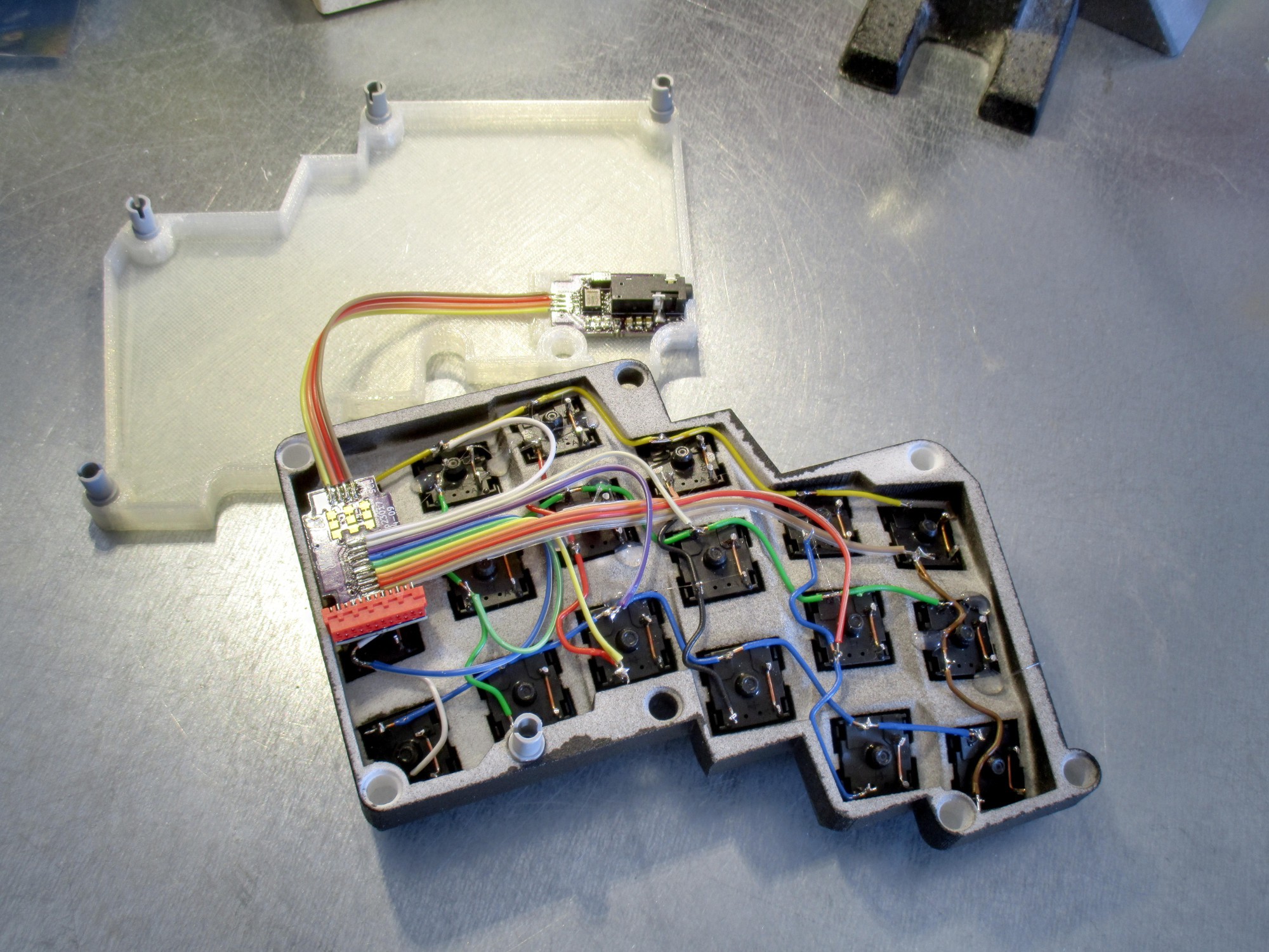
this picture shows two modules in action: an I2C_secondary_bridge in the bottom-shell, and a matrix_mcp23017 connecting to the key-matrix, with the red expansion header going to the thumb-cluster layer on
![]()
the thumb cluster is basically one row, which is run from switch to switch, and six columns, run to each switch separately
![]()
![]()
-
Them Modules...
05/01/2017 at 17:36 • 0 commentsa quick overview of the modules used (so far), which contribute to the 'M' in the projects name and are designed to support/simplify the (hand) wiring of the keyboard matrix
![]()
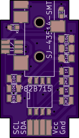
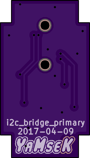
the I2C_bridge_primary
sits on the microcontroller side (which runs the firmware and does the USB stuff)
it's main features are
- I2C buffering (for long/unshielded wires)
- ESD protection
- current limiting
![Order from OSH Park]()
Parts:
- TRRS phone-socket SJ-43514-SMT
- current-lim. IC: AP2553W6
- I2C Buffer P82B715
- ESD diodes VESD05a1
- 0805 resistors and capacitors
![]()
![]()
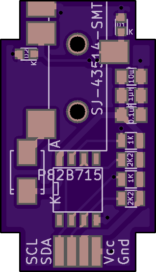
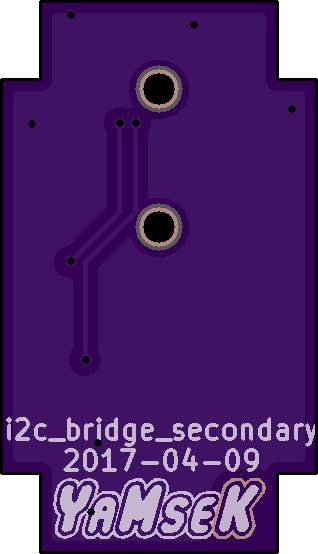
the I2C_bridge_secondary
sits on any of the slave devices (usually one/another keyboard half, but could be multiple other devices)
it's main duties are:
- I2C buffering
- ESD protection
![Order from OSH Park]()
Parts:
- TRRS phone-socket SJ-43514-SMT
- I2C Buffer P82B715
- ESD diodes VESD05a1
- schottky diode SS14
- 0805 resistors and capacitors
![]()
![]()
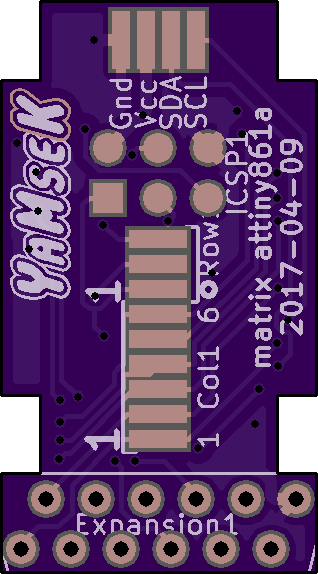
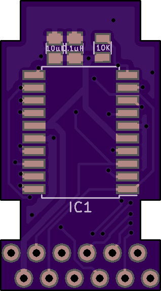
the matrix_Attiny861a
mostly an breakout board for an attiny, with pads on the front to directly solder a ribbon-cable which spreads out to the handwired keyboard matrix
- ICSP contacts for reprogramming
- pads to solder a 4-wire ribbon cable to the device-internal i2c-bus (with the attiny running an i2c-slave firmware)
- an expansion header which can be fitted with an 2x6 micro-match connector to add more keys or use the ADC for an analog joystick
![Order from OSH Park]()
Parts:
- micro-match socket 1-215460-2
- attiny 861a
- 0805 resistors and capacitors
![]()
![]()
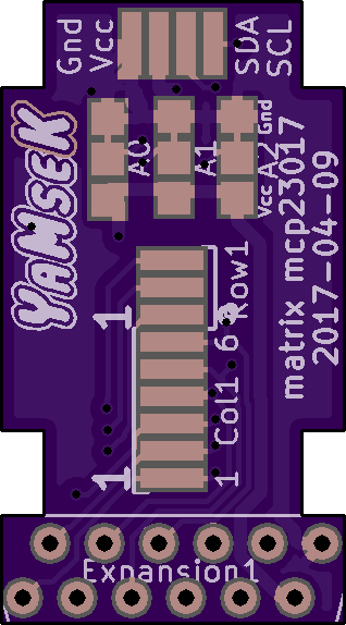
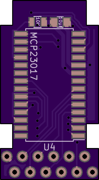
the matrix_MCP23017
- a breakout board for the I2C port-expander
- with pads to directly solder a ribbon cable which spreads out to the keyboard matrix
- as well as a ribbon cable to the internal i2c bus
- 2x6 micro-match expansion header for additions to the keyboard-matrix
![Order from OSH Park]()
Parts:
- micro-match socket 1-215460-2
- MCP23017
- 0805 resistors and capacitors
![]()
![]()
-
blender-ing a digital prototype
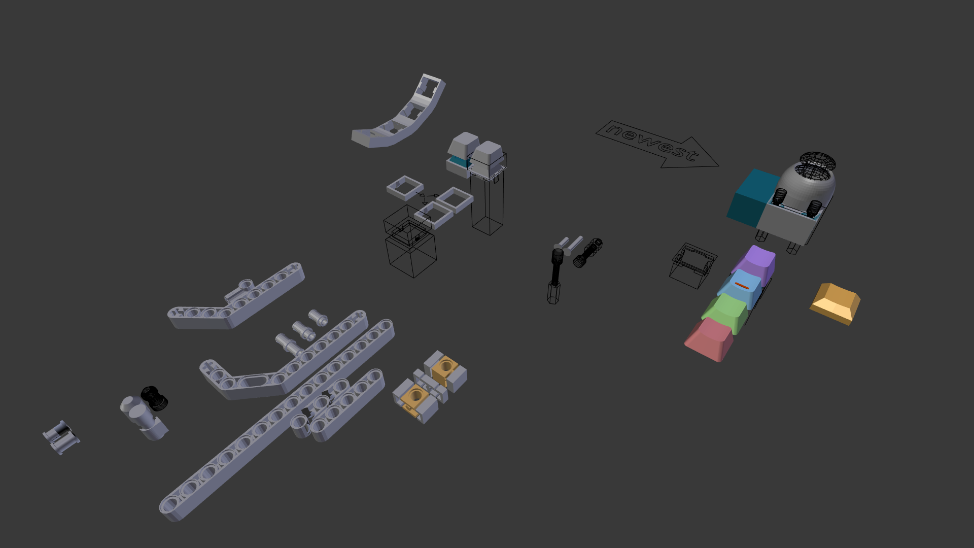
04/14/2017 at 07:35 • 0 commentsStep 0
starting point is a collection of 3-d models for some basic components and real-world parts:
- a cherry-mx switch
- the switch body itself
- sculpted keycaps (each row on a standard keyboard has a slightly different shape)
- a basic frame to hold the switch (adapted from the dactyl keyboard mesh)
- some lego technic parts:
- pins and meshes for cutouts with boolean operations
- partial meshes to generate beams and long bricks with array modifiers![]()
and as reference the minimal meshes of the ergodox and dactyl-keyboard matrices
(the flat ergodox part was an SVG import, and for the dactyl keyboard mesh all but the vertices/faces that form the mounting plate where removed)
![]()
![]()
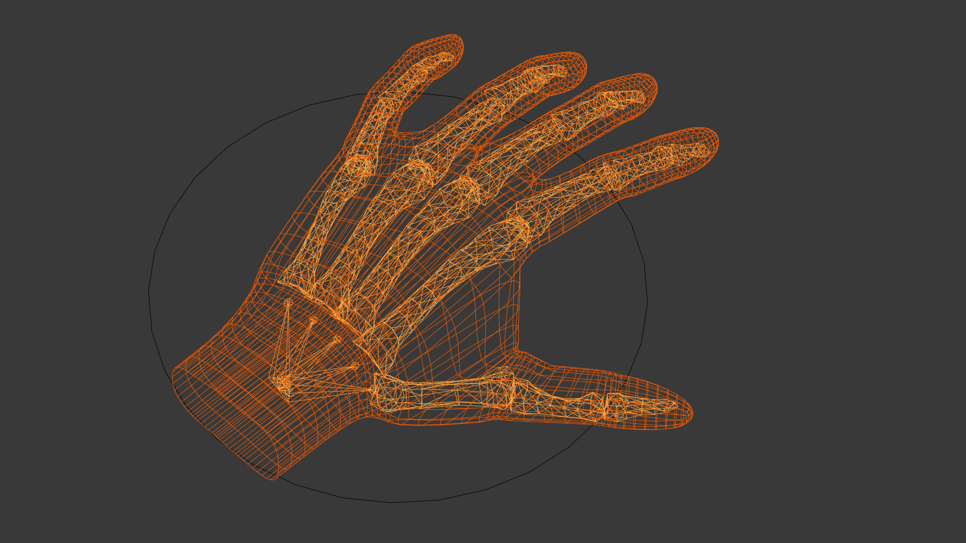
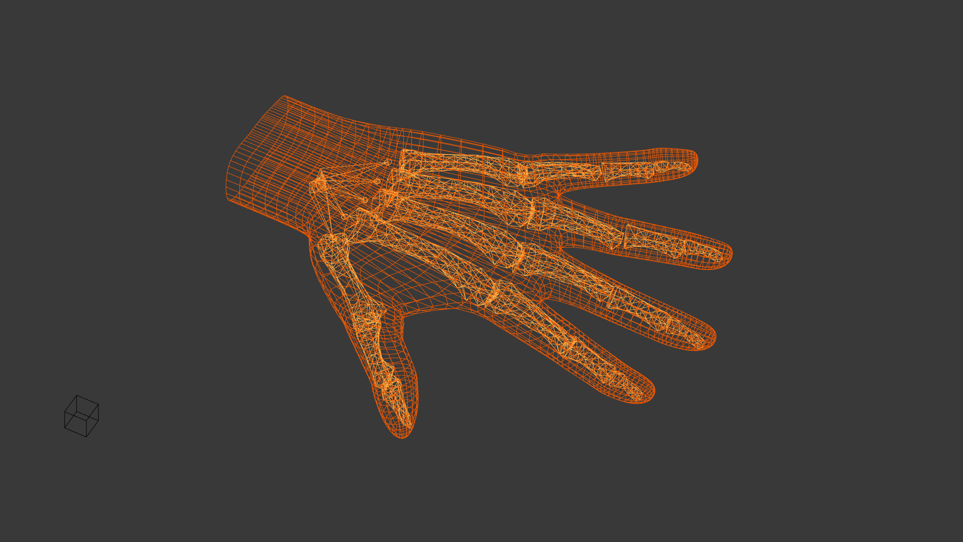
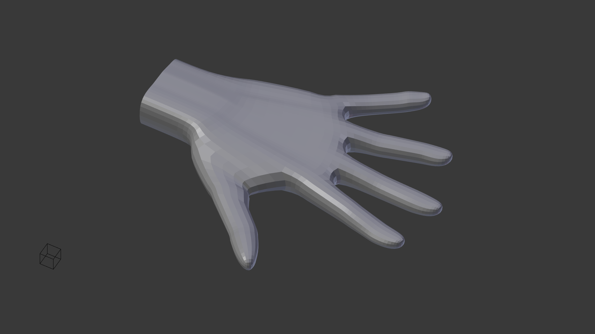
Step 1: the hand model
to get a digital hand model like this
![]()
some research is in order:
turns out that even though there is no one-size-fits-all 3d model - creating a model based on ones own hand isn't too difficult:
- getting to know the different parts from The Anatomy and Mechanics of the Human Hand helps in further web-searches
- next step is to get a digital model of the human skeleton from the inter-webs - which can be taken as a base model, but has to be adapted to reflect the proportions of ones own appendages...
- at this point Proportions of Hand Segments was very helpful - seems that there is an average amount of tissue surrounding our digits and the bones of each digit follow a somewhat predictable ratio pattern
- there are also some interesting papers on the ranges of motion of the human hand, and how to properly animate one; like Handrix: Animating the Human Hand
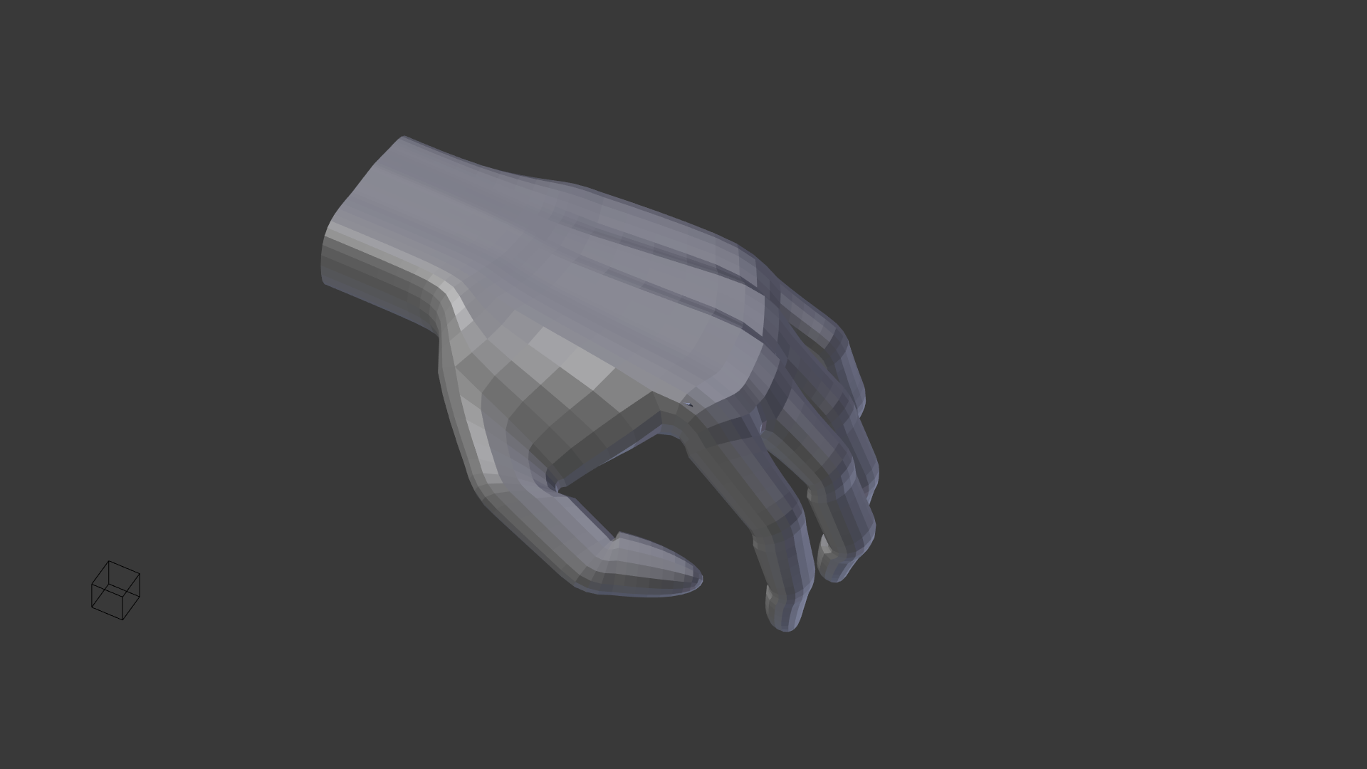
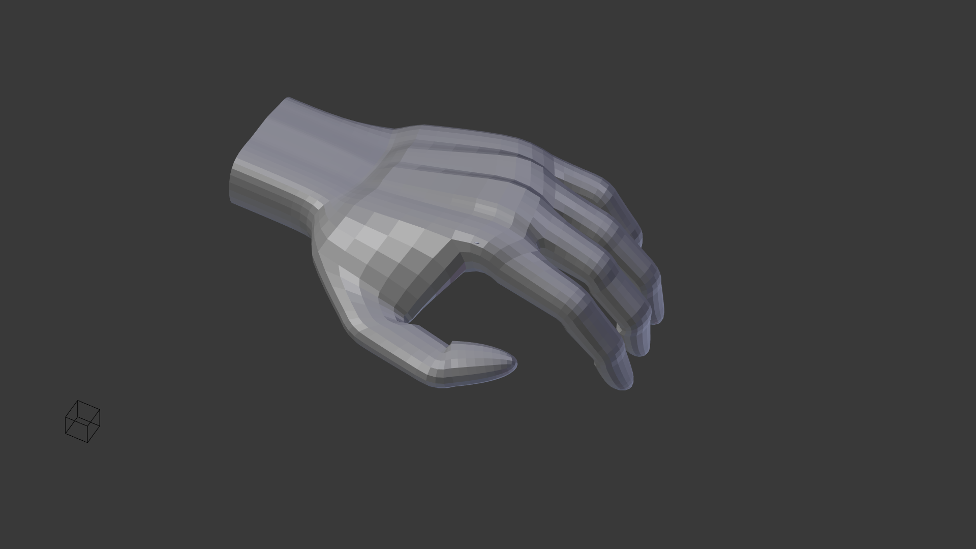
with all that, and some measuring tool a hand model can be modeled and rigged, to be posed in a relaxed position or touching various keys of the digital model later on
![]()
![]()
![]()
![]()
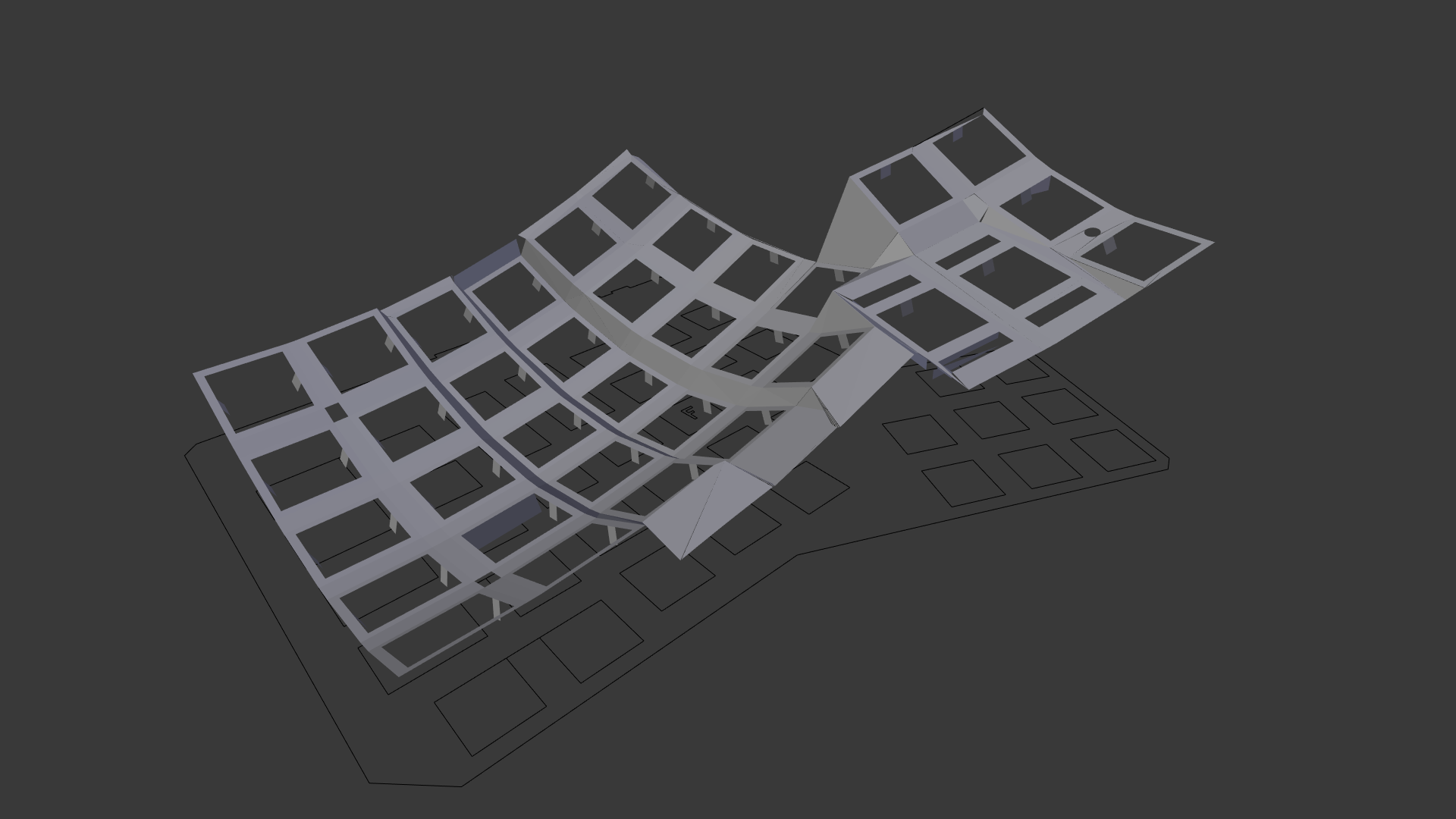
Step 2: rigging the mounting plate
the next step is to build a mounting plate for the keyboard matrix, that is rigged in a way to ease rapid prototyping:
the mesh itself is an armature, with the cherry-mx bodies as bones which in turn follow the keycaps world-positions, stretching the mesh for the mounting-plate in turn
![]()
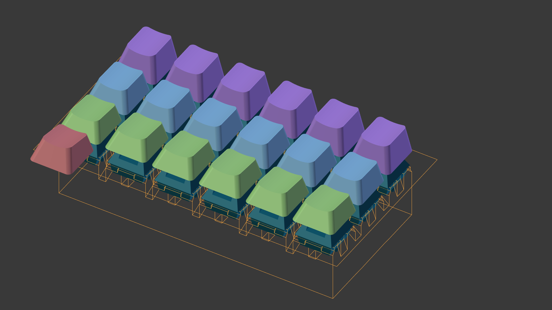
![]() Step 4: rapid prototyping
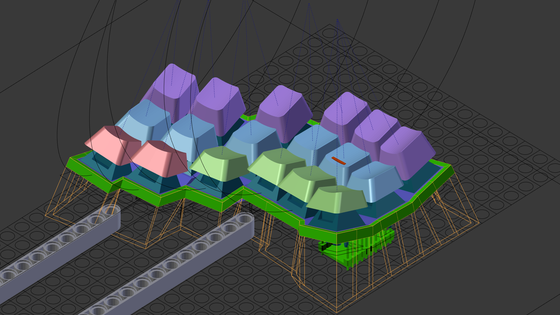
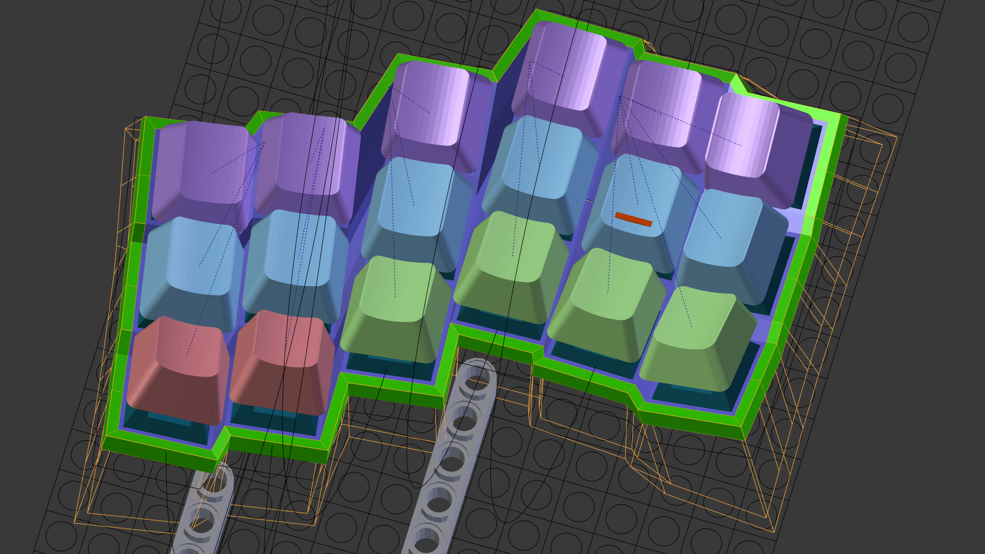
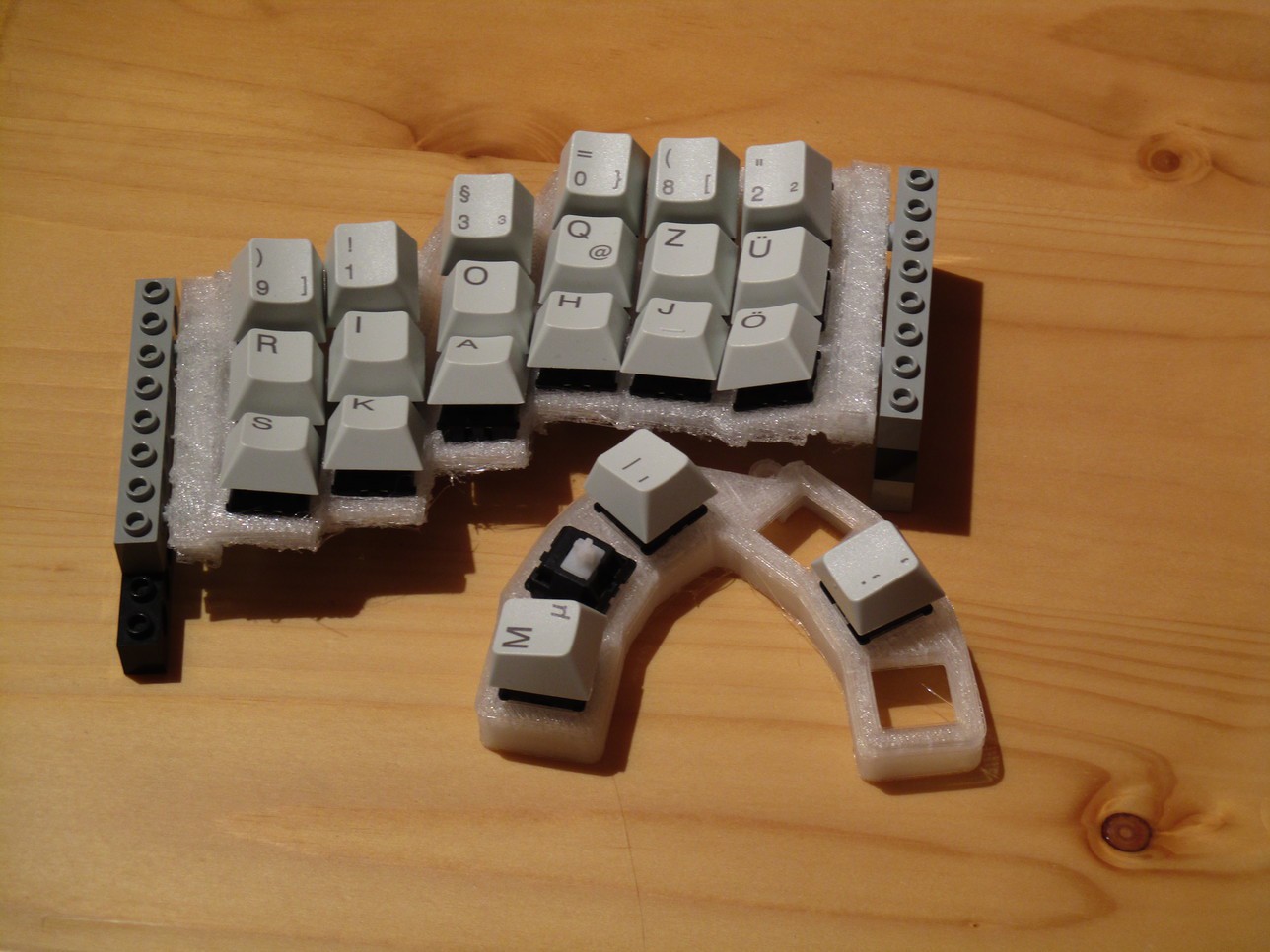
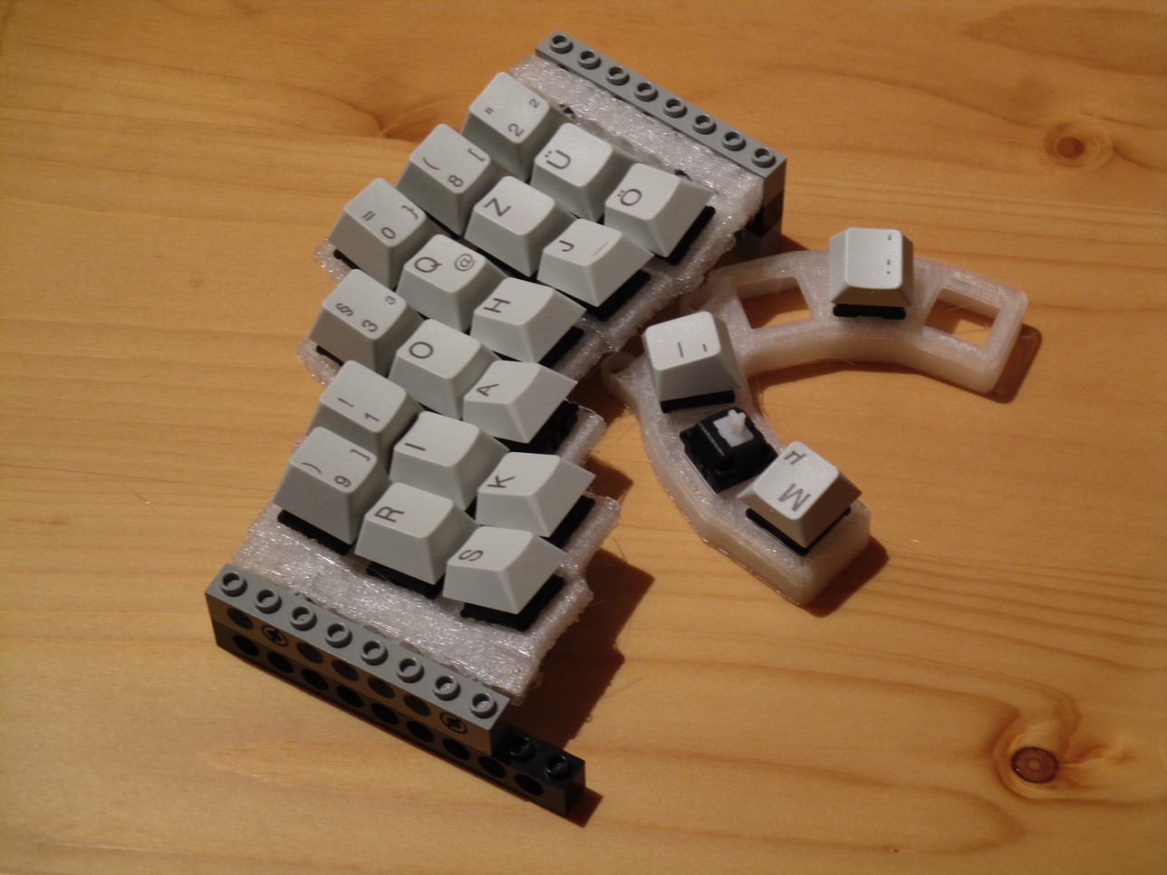
Step 4: rapid prototypingwith the hand and mounting-plate models one can start pushing around the key-caps, starting of at a position somewhere between the ergodox and dactyl references.
![]()
![]()
these two pictures also shows some of the circles which where used as guides for the curvature, as well as the lego-grid for the hard-points added later on
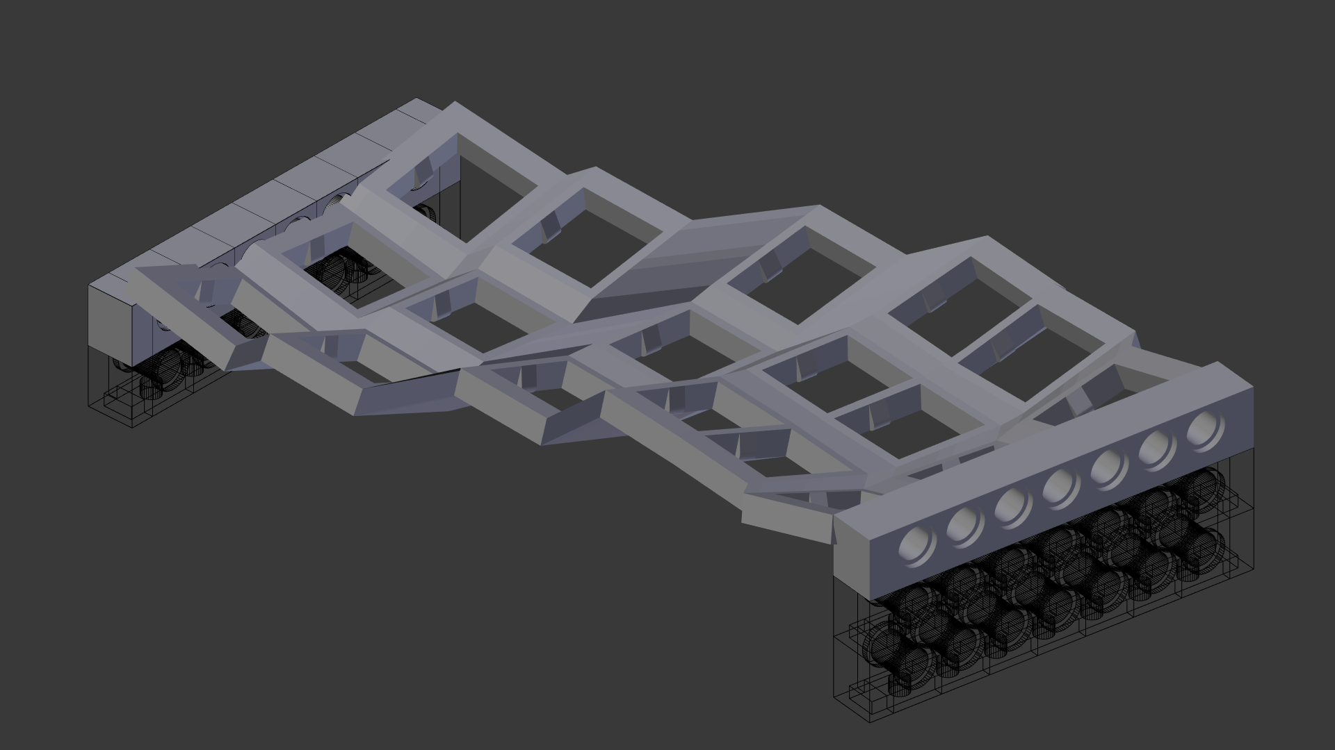
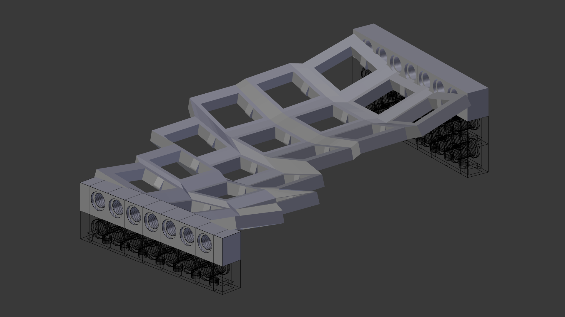
adding lego compatible blocks at the edges of the mounting-plate the size of the 3d printed part can be kept at a minimum while still allowing height and tilt adjustments
![]()
![]()
from here its a few iterations of "adjust&reprint", to get a custom (and hopefully comfortable!) key arrangement
Step 5: cleanup for production
to get a 3d model that is closer to the finished some more cleanup is necessary:
- resolving intersecting edges and thin parts, due to armature deform
- straightening the outline, based on a lego grid (8x8mm)
- adding "hardpoints" (e.g. lego-technic pin holes) to later mount the backplate and other attachements
![]()
similar steps for the back-plate:![]()
the highlighted part shows how far the switches extend from the front plate - this is used to position the electronics and cutouts/support for the cables.![]()
-
rekindled interests
04/13/2017 at 17:52 • 0 commentsbut thanks to a recent post on the hackaday blog, which led me to an even older article titled "One man’s adventures in custom keyboard development"
the old project just begged to be given another chance - so it was unearthed, the remaining (and rather dusty) parts reexamined, disassembled, recycled/disposed and soon new prototypes followed:
... but going back to the monolithic parts was a bad motivation wise...![]()
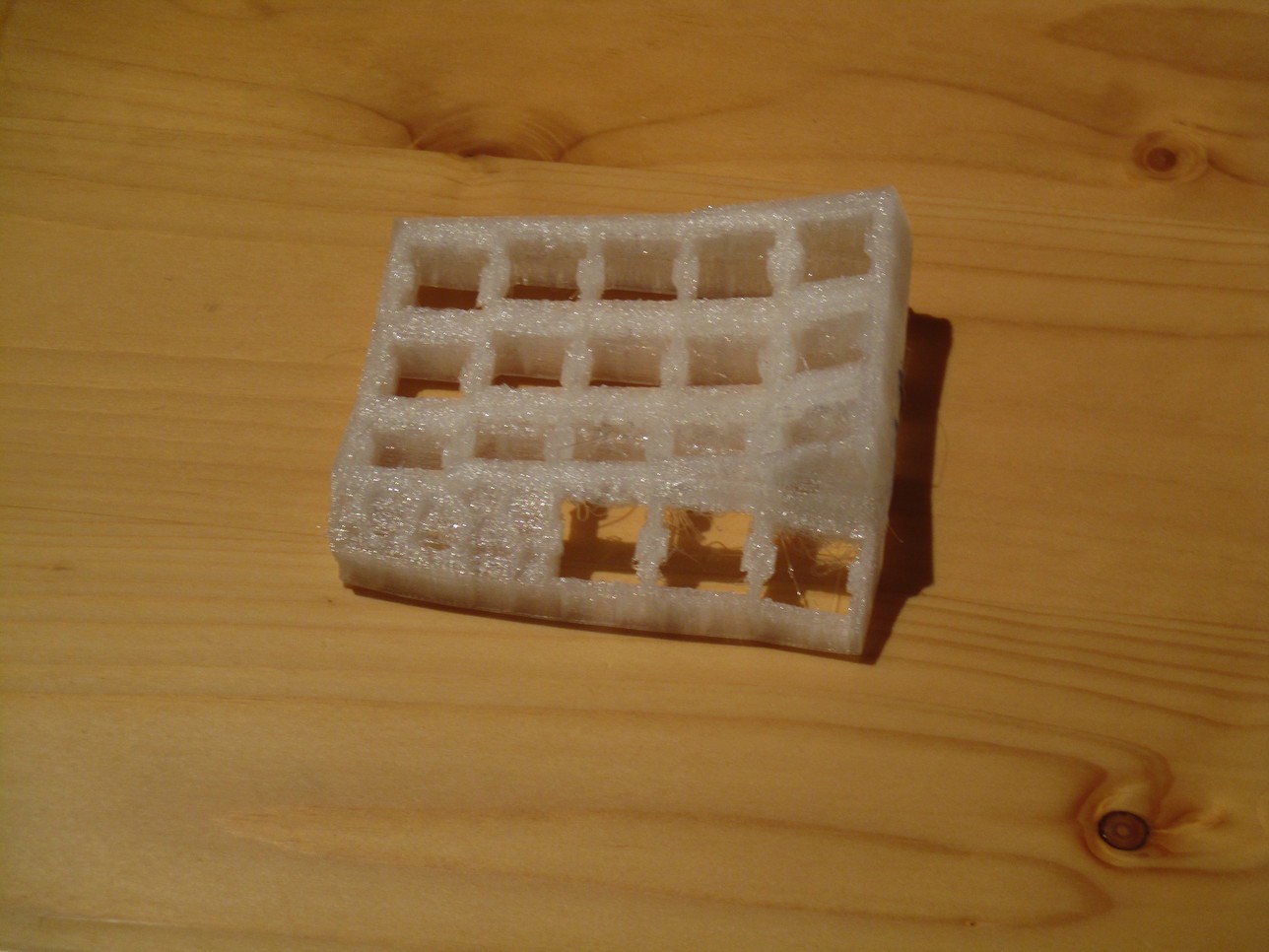
stripping the parts to an absolute minimum helped, but they still took too long to build![]()
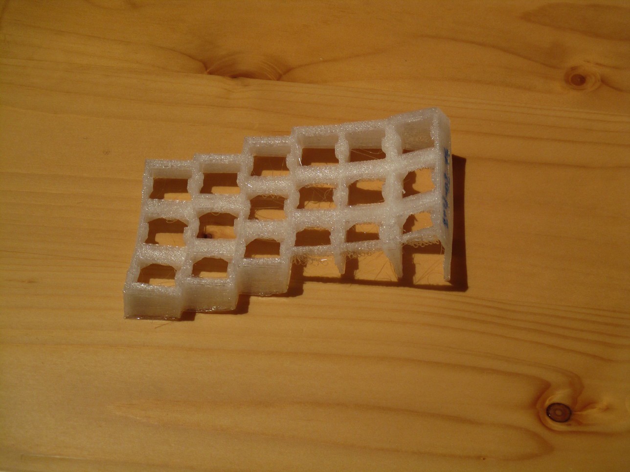
turned out that using everyones favorite construction toy helped a lot!
it now became relatively easy and fast to print a minimal keyboard matrix making (slightly) changes to the curvature or the column/row layout, change the amount of tilt (or more exotic stuff like "tenting", ...)
as a bonus it became a breeze to add attachments to the prototypes to see how well the various combinations would work out :-D
![]()
![]()
YaMseK
Yet Another Modular Split Ergonomic Keyboard a custom 40-60% keyboard with a columnar+curved keyboard layout and an attached thumb-cluster


 Step 4: rapid prototyping