-
Quick update
09/28/2014 at 22:47 • 0 commentsWith the deadline for the next stage of the Hackaday Prize looming, a brief update is probably necessary:
While progress on this project is still ticking along slowly (I'm just bad at continuous project logging), the boards for the next hardware iteration won't be here for another couple of weeks, let alone the deadline in a few hours. As such, I can't show a video of it working, making it a bit difficult to qualify for the next set of judging. On that note, a lot of the other current entries out there look really awesome - I can't wait to see how some turn out.
The circuit design for the next hardware iteration turned out to be more of a drastic change than I'd originally planned - the only component in common is the LIS3LV accelerometer (the HIH6131 humidity/temp sensor has been replaced with the more accurate, but otherwise identical, HIH9131). Of particular note is the removal of the ATmega328P - I'm attempting to do all the sensor logic in the new Bluetooth module, rather than a separate microcontroller. The Bluetooth module being used for this is actually pretty interesting - a BlueGiga BLE113. This module allows applications written in a script langauge to be run on the same hardware that manages the Bluetooth comms, with access to several GPIO ports, UARTS, and SPI. It is also a Bluetooth Smart device, and so should draw considerably less power than the previous iteration.
Battery management and power regulation is now handled by an LTC3553 - a really useful chip made by Linear Technology that incorporates a USB LiPo battery charger, a buck regulator, and an LDO regulator into one device. By default the LDO is not being used in the new iteration, but a jumper has been included in case the switchmode regulator turns out to interfere with the Bluetooth in testing.
Much of the last week has been spent getting my 3D printer up and running again, so I should have some new enclosure designs ready in a week or two. One of the largest challenges I'm having with this at the moment is designing an enclosure that is both strong and light enough - it needs to handle being rolled on top of when the wearer is sleeping.
Even further ahead, once the new PCBs are together and working, is the Android app redesign. A lot of the app will need to be rewritten from scratch, as the APIs dealing with Bluetooth Smart in the newer versions of Android differ significantly from the old (admittedly horrible) interface to Bluetooth Classic.
It might be a while until the next update, but if anyone has questions, please don't hesitate to ask.
-
Bluetooth Comms
08/21/2014 at 06:27 • 0 commentsA key part of the current system and how it works is the Bluetooth communication between the sensor device and the Android phone. As a mobile device, the power supply is limited by a relatively small battery. When connecting or sending data, the current draw from the Bluetooth module vastly outweighs anything else in the circuit, peaking around 28 mA and averaging closer to 18 mA. To stop this from quickly flattening the battery, the data exchange is instead periodic, and is adjustable from the Android app.
As neither device wants to leave the Bluetooth connection discovery running (this will significantly drain even the larger battery found in a phone), both devices need to be synchronised, so they can reach out and start burning power at around the same time, quickly exchange information, and power down again. The duty cycle of this communication can be very low (data exchange is only a couple of seconds, and the waiting period is often up around 15 minutes), and so loss of synchronisation can be disastrous, as the device needs to keep the Bluetooth turned on for the entire next 15 minutes.
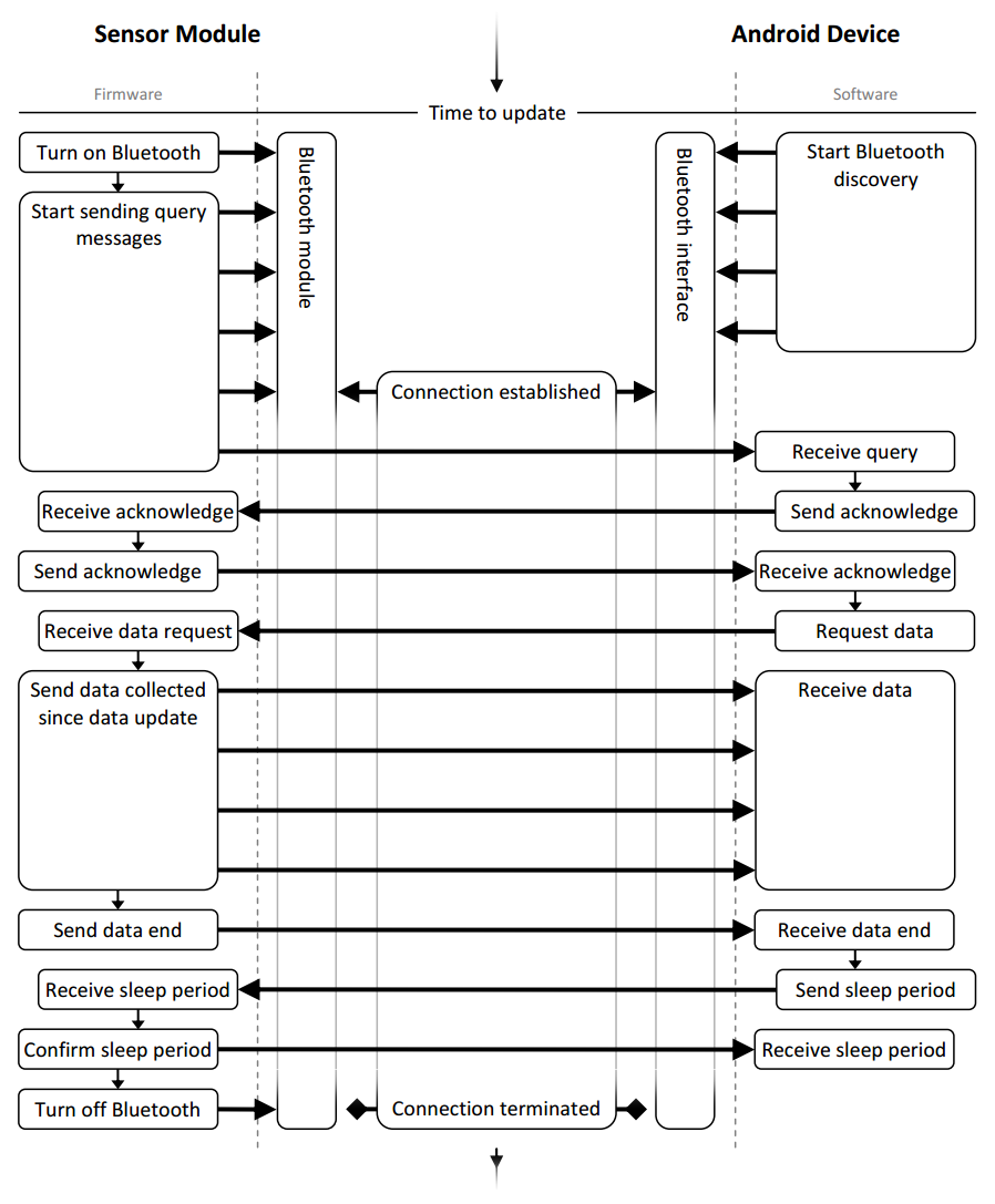
To try and combat this, the current system uses pretty standard acknowledge messages which can be seen in the flowchart...thing, below.
![]()
To stop the sleep periods from drifting out of sync, the Android app dynamically controls the sleep period of the sensor device at every data exchange, telling it how long it should wait before waking up again. As well as allowing a means for the user to change the sleep period, this also neatly allows for delays in the process that can occur if the Android phone is being used heavily at the time, delaying the background communication service.
I probably should also point out the large difference in power consumption between simply waiting for a Bluetooth connection, and trying to find one (finding one, called discovery, consumes much more). Accordingly, when the sensor device turns on the Bluetooth module, it simply starts spitting out query message on the USART, even though none will actually get anywhere until the Android app initiates a connection.
With that, I've only got a couple more pretty diagrams left to talk about, namely the AVR firmware and the Android app structure. If anyone wants more information on an aspect of the system, let me know and I'll write another log about it.
-
Hardware Design Breakdown
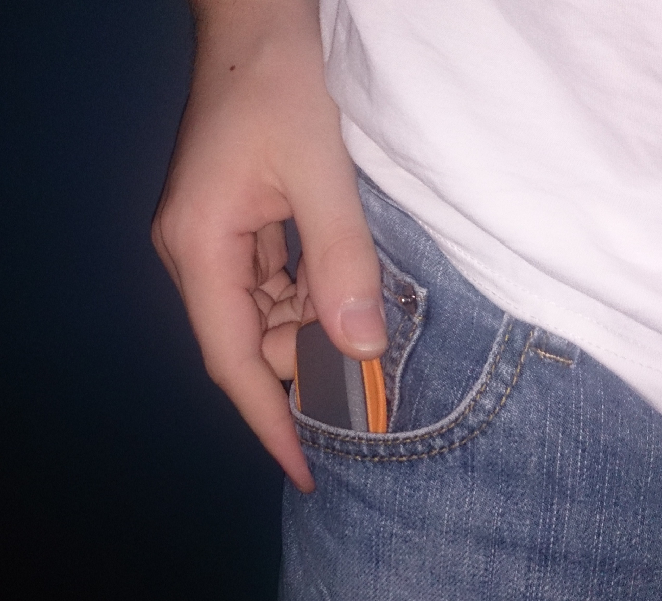
08/21/2014 at 05:51 • 0 commentsI will admit to committing a cardinal sin of electronic device design - I picked the enclosure before designing what needed to go in it. This is one of the reasons I'm designing another hardware iteration, and had a few implications that can be seen in the current device - there is way too much empty space, the battery is being just slightly compressed, and the USB port is sticking out the large, flat side of enclosure, rather than the edge.
Enclosure
The enclosure used is part of the OKW Minitec range. They're pretty diverse enclosures, and you can order the different parts in lots of sizes and colours to mix and match. This one appealed to me simply because I wanted to try and cram the device into something small, and it was curved and comfortable to hold while still offering mounting points for a strap. It comes apart into three pieces, with the center ring being made of a flexible rubber.
![]()
To make room for the USB port, a hole was drilled in the front face, along with two smaller holes in the underside to let air flow through to the humidity sensor.
PCB
Having a curved enclosure might be great for aesthetics, but it really does make the PCB design a bit of a pain. Unable to find a way to generate a cross-section at the point where the PCB meets the enclosure edge, I actually resorted to manually cutting the CAD model and reading off vertex coordinates, translating them to line dimensions in KiCad. It took...a while, and I wouldn't recommend anyone else doing it that way, though it does seat quite neatly on the curved inner surface. I'm pretty sure the newer version of KiCad can now import DXFs anyway.
![]()
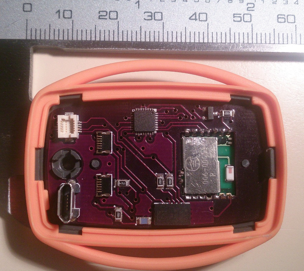
The general PCB layout was dictated by the larger components that really only had one place to go. The Bluetooth module can be see down one end, inset into a cutout. Not only did this make it easier to solder to the edge castellations that the module uses, but it was the only way to keep the board thin enough to fit under the battery. Note that the end around the chip antenna is essentially empty of components and pours - the Bluetooth datasheet was pretty specific about this, and it makes sense to keep interference away.
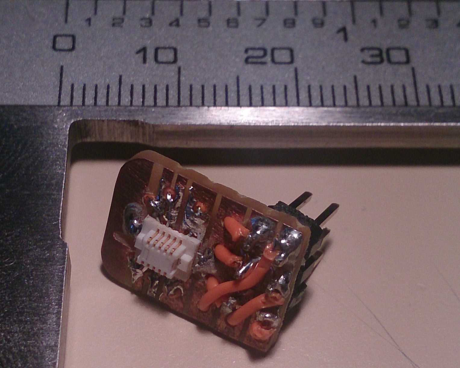
Up the other end is the USB and programming connectors. Both were too tall to fit underneath the battery that lays over the board. Finding a connector that would fit inside the enclosure but still allow a vertical connection for programming was difficult, and I eventually the DF12 series of surface mount stacking connectors. The pitch on these things is tiny, and it wasn't until construction that I actually thought it through and realised an adapter to the standard 6 pin ISP would be needed. Turns out you can do some pretty tiny stuff with strip board and a craft knife.
![]()
To the right of the USB connector are the battery terminals. The intention here was to get something that could clamp onto the thin tags used on flat LiPo batteries, and I bought some FPC connectors to try - using all pins on each connector to clamp onto the tag. This actually worked pretty well, other than the difficulty of closing the connector down once the battery is on top of it (requires very fine tweezers).
Everything else was pretty much standard layout procedure - the power supply and humidity sensor are on the reverse side, to spread around the board realestate a little. That said, I've learnt a lot since making these boards, and so won't be surprised if people find things that could work better. I'm always happy to learn though, so let me know in the comments.
-
Circuit Design Breakdown
08/21/2014 at 02:38 • 1 commentMicrocontroller
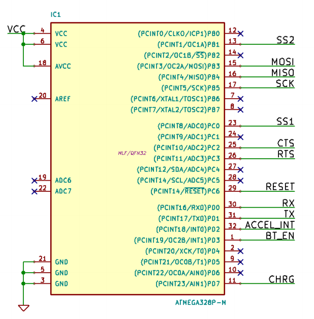
The sensor device is designed around an ATmega328p AVR - a microcontroller I have a fair amount of experience with, and one that will be immediately familiar to anyone who has ever used an Arduino. Even when communicating with the rest of the circuit it draws little power - only a couple of mA. It provides both the USART used to communicate with the Bluetooth module, and the SPI port to communicate with the two measurement chips.
![]()
Humidity Sensor
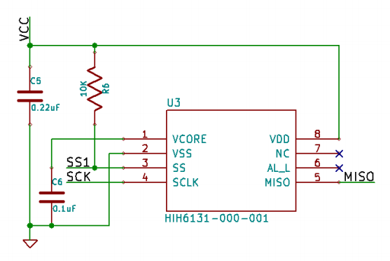
The first, and most important of these, is a Honeywell HIH6131 digital humidity/temperature sensor. After the issues I had with the SHT75 in the previous iteration, this chip was appealing in that it had a hydrophobic filter to prevent water from throwing measurements off, and used standard SPI as the interface. It also integrates a temperature sensor, which is both directly accessible for measurement and automatically corrects the humidity reading. Interestingly, the datasheet also notes that this sensor is able to rehydrate in ambient conditions after soldering (a lot of other humidity sensors require rehydration in a very high humidity environment to start working properly).
![]()
Accelerometer
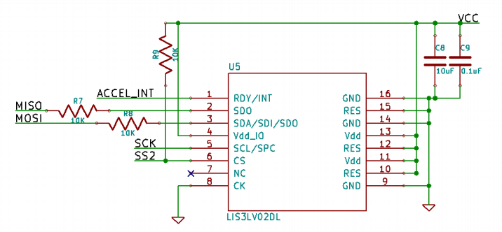
The other measurement chip is an LIS3LV, a 3 axis accelerometer made by STMicro. This relatively cheap accelerometer is actually extremely capable, measuring with 12 bits at either 2G or 6G ranges, all the way up to 2650Hz. While not completely necessary, the circuit design was already using SPI, and it I was curious to see if there was any correlation between movement during sleep and hypoglycaemia events. This came back to bite me in a couple of ways.
Upon closer inspection of the datasheet (read: after ordering everything), it turned out that the comms protocol it uses isn’t quite standard SPI - when the Slave Select line (SS2) is pulled high to disable the port, it switches to I2C mode rather than going to high impedance, messing with anything else you’re trying to communicate with. R7 and R8 allow this to work anyway, but do limit the maximum SPI clock speed somewhat (I do have an oscilloscope trace lying around somewhere, and there is obvious rounding of the edges when the accelerometer is driving MISO compared to the humidity sensor).
![]()
Bluetooth
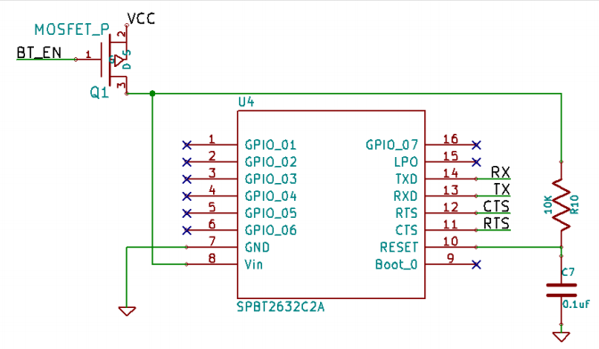
While the prototype device used a pretty generic serial/Bluetooth adapter, I needed something smaller to fit in this iteration. I eventually found a pretty tiny module made by STMicro, the (bit long winded) SPBT2632C2A. It includes it’s own chip antenna and is only 11.6 mm by 13.5mm. It’s also a bit unique in that it uses edge castellations for data connections instead of pins. Other than that, it functions essentially the same as any other serial/Bluetooth adapter - you turn it on, connect it with a bluetooth device such as a phone, and serial data going in one end comes out the other.
When connecting and transmitting, this module draws by far the most significant amount of current in the whole circuit - around 18mA. To avoid flattening the battery too quickly, the microcontroller uses a MOSFET to turn the Bluetooth module on only when data needs to be sent.
![]()
Power Supply
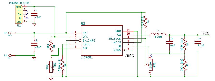
All of this is powered with a 2.7V switch mode supply, running off a small 400mAh LiPo battery. The regulator used also actually handles the battery charging functions, all combined into a single chip made by LT - the LTC4081. Power supplied via a micro USB port at 5V charges the battery, which varies from 4.2V when fully charged, down to 3.3V when flat. A buck regulator then pulls this down to 2.7V. RV1 is a trimpot to adjust the battery cutout voltage, and the various other passive support components set the battery charge current, supply voltage, and temperature cutout.
![]()
-
The Road So Far
08/21/2014 at 02:09 • 0 commentsThis project has actually been quietly sitting on the back burner for quite a while - the majority of work was done in 2013 as part of my undergrad EE final year project. It began even before that though, in early January that year.
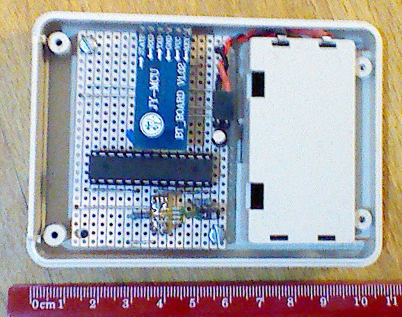
The idea itself was put forward to me by my Dad, a Type 1 diabetic himself, as a possible way to mitigate the ever constant risk of hypoglycaemia in the early morning while asleep. A quick and (extremely) rough prototype followed - pictured below, little more than an SHT72 humidity/temperature sensor, a generic serial to Bluetooth adapter, an ATmega8 and a 5V linear regulator all crammed onto some stripboard.
![]()
The Android app developed to communicate with it was similarly thrown together, and though the sensor prototype itself was hardly small enough to be convenient when sleeping, we did get some good data. Humidity and temperature measurements themselves proved to be a problem - readings from the SHT72 I was using could sometimes be horribly unreliable, a problem I never did get to solve. Between that and the increasing workload as I started the final year of my undergrad EE course, progress on the project faded.
The more interesting parts of the current system came about after I picked it as the subject of my final year project several months later. Focus went largely on designing and producing a more convenient, reliable, and portable sensor device. Learning to use KiCad was a pretty steep learning curve, but was definitely worth it. Boards were ordered from OSH Park, and turned out great, though I did have some trouble getting the reflow process right (using a $25 toaster oven from Kmart). The STMicro Bluetooth module used on the current board (the SPBT2632C2A) was actually really hard to get hold of - even though it was advertised on various US electronics suppliers such as Digi-Key and Mouser, and even Element 14, everyone seemed convinced I was going to make missiles or something with it. Indeed, I was eventually able to get them from Future Electronics in Canada, but only after I signed a declaration saying I wasn't going to do anything malicious with them.
Frantically trying to get everything built and working, along with writing my thesis, before the submission deadline meant that the system in it's current state never actually got tested or used much, and the whole project fell by the wayside after submission as uni wrapped up.
What's Next
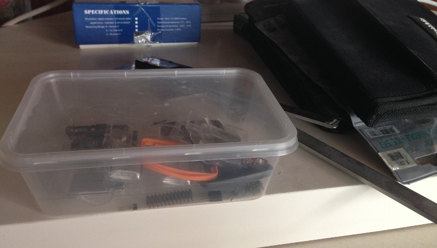
Having such a potentially useful system just sitting in an old Chinese takeaway container on a shelf is a bit sad. It's something I've wanted to get back into for a while, but never quite pulled together the time and effort (a pathetic excuse, I know). The Hackaday Prize has provided just enough kick to get me to do something about it - I think it's a really good chance to share it with other people and get some wider input and opinions on the project, which is really what it needs at the moment.
The current plan forward from here is to design and build another hardware iteration, cleaning up a few of the issues the old one had, such as the enclosure shape, hard to find Bluetooth chip, power usage, battery connectors, and lack of indicator light and power switch (seriously, I have no idea how I missed that...). The Android application itself also needs an update, it currently has some timing issues when synchronising with the sensor device, and I'd like to have a look at the newer Bluetooth API that recent versions of Android have introduced (the old one is, put simply, broken and horrible).
For those interested in the design of the current system and how it works, the next few project logs will break down the different aspects of the system and how they were designed. Feedback, especially suggestions, are welcome in the comments.
Hypoglycaemia (low blood sugar) alert system
A compact Bluetooth device that acts as a safety net for sleeping type 1 diabetics, detecting hypoglycaemia and calling for help.
 novirium