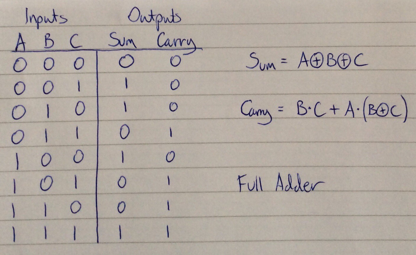
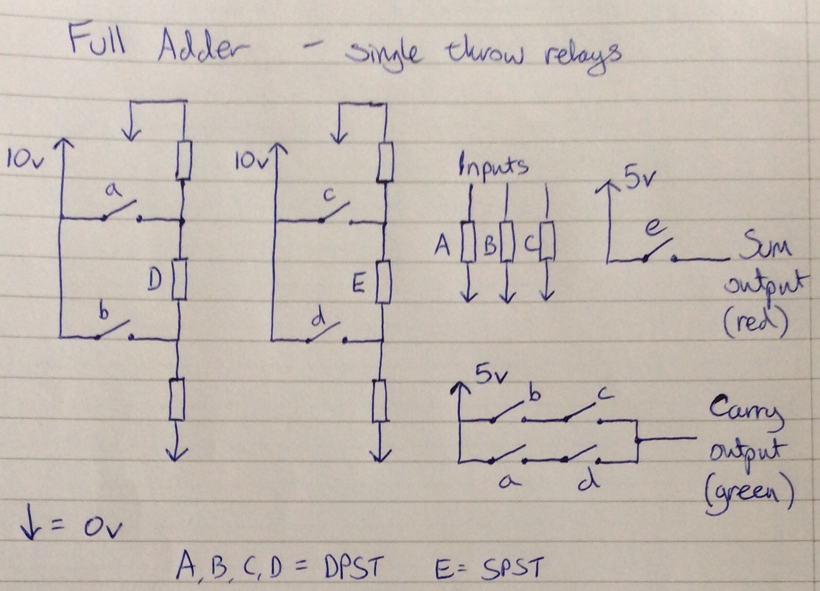
Ideas about using single throw relays for computing, and working prototype circuits.
To make the experience fit your profile, pick a username and tell us what interests you.
We found and based on your interests.
This video shows a full adder made using 4 DPST reed relays and 1 SPST reed relay. All combinations of inputs are cycled through.
Below is a truth table and the circuit diagram followed by an explanation [explanation added following discussion in comments]:
The rectangles labelled with upper case letters represent relay coils. The corresponding contacts are represented using lower case letters. The unlabelled rectangles represent resistors, where the resistance is equal to the resistance of a relay coil. All of the relays used have a coil activation voltage of 5V.
All inputs and outputs use the same convention to represent binary digits 1 and 0: 5V represents 1, and no connection represents 0.
D and E are used to implement XOR gates. Relay coil D will activate if either a is closed, or b is closed, but not if both are closed. Similarly coil E will activate if either c is closed or d is closed but not both. Contact e can therefore be used to obtain a XOR b XOR c, i.e. the sum of the inputs.
Because relays A, B, C and D are double pole, the second set of contacts in each can be used to implement the carry function - the ladder arrangement in the bottom right of the circuit diagram.
Create an account to leave a comment. Already have an account? Log In.
Good evening Will, just wondered if you will ever be making any updates. My 4-bit computer project will be using some home made relays and always looking for information :-)
Become a member to follow this project and never miss any updates
Reed relays exist also in dual throw, moreover I think they might be done from cheap reed switches (e.g. https://it.aliexpress.com/item/32947287626.html?spm=a2g0o.cart.0.0.1fb73c009qLgQj&mp=1) with some wire rounding...