Close
0%
0%

One-instruction TTL Computer

A breadboard-able computer which uses only a single instruction - MOVE

Similar projects worth following
This project is my attempt at making a computer which has only one instruction - the move instruction. Specifically, to move data from one location to another location. Those locations can be either registers or RAM or other special functions. This will be my submission for a neat small breadboard computer built by hand.The specific type of computer is called a Transport Triggered Architecture, but the triggering will be very simple. It works by moving data from one location to another. Every function has a memory location. To perform that function, you only need to move data to those memory locations. For example, to perform an ADD, just move bytes to the two ADD memory location, and the result will show up in the third memory location on the next clock. So the programs will only be a series of source and destination addresses.

Project status:

I have a working version of the architecture simulated in VHDL. It is synthesizable, and I have downloaded it to an Artix-7 development board - the Digilent Cmod. I have a few simple programs running with a UART interface. I have a bootloader/monitor running so I can load programs over the UART.  I've written a simple assembler to generate machine code I can send to the bootloader.   I've finished a schematic and layout for making a PCB.

Primary project goals:

  1. Implements only one instruction - move
  2. Can be built using a minimal number of simple DIP components (74xx TTL circuitry).
  3. All components are active. No obsolete or hard-to-find components. All components in stock at popular distributors.
  4. Useful - it needs to be able to run programs in a short amount of time.

Secondary project goals:

  1. Useful input mechanism. I expect a set of DIP switches for the input, but I'd prefer something more useful like a UART port or maybe a keyboard.
  2. Useful output mechanism. I could do a simple LED numeric display, but I'd prefer something more useful like a UART or at least a 4x20 character display. Perhaps I'd even do a video memory with a separate display.
  3. Easy and natural loading of programs. I'd prefer not to have a roundabout way to load programs into memory. Perhaps even use the above UART to send programs.
  4. Easily expandable for more memory. I'd like to be able to load very large programs.
  5. Write/adapt a compiler/assembler. I'd like to be able to take existing programs and compile them to run on the computer. This would probably be the last thing I do considering the complexity.

PCB Assembly Plan: bold is completed

  1. Clock circuit with single-step mode and Reset
  2. Control state machine with AND/NOT gates and control LEDs
  3. Program counter Low and High with Memory Address Buffers and address LEDs
  4. Control Decoding
  5. Instruction ROM and data bus LEDs
  6. Src/Dst Hi/Lo registers with data buffers and Src/Dst decoders
  7. Source Hold Register
  8. Program counter Temp register and data buffers
  9. ALU A
  10. ALU '171 chips
  11. ALU result reg
  12. AEB/Carry FFs/buffers
  13. Pointer address registers
  14. UART
  15. RAM

Memory Map 16.xlsx

Memory Map for the rev A schematic

sheet - 16.90 kB - 11/08/2017 at 13:04

Download

OneInst.PDF

Schematic of the PCB rev A

Adobe Portable Document Format - 1.57 MB - 11/08/2017 at 13:04

Preview

Clock.pdf

Clock circuit schematic

Adobe Portable Document Format - 119.50 kB - 06/16/2017 at 17:28

Preview

  • 1 × Texas Instruments PC16550D UART interface chip
  • 2 × Texas Instruments SN54LS181 4-Bit ALU
  • 4 × Texas Instruments SN54ACT245 8-bit bus transceiver with 3-state outputs
  • 2 × Texas Instruments SN74ALS867A 8-bit counter
  • 9 × Texas Instruments SN54ALS996 8-bit Register with readback and tri-state outputs

View all 7 components

  • Revisited architecture

    Justin Davis01/10/2020 at 20:56 1 comment

    I've been thinking about this project lately which I eventually got working, but wasn't completely satisfied with it since I didn't technically complete the project goals.  Specifically, the 74181 chip is obsolete.  My goal was not to use any obsolete chips.  Not sure why I didn't see that from the start.  

    I've been reviewing other people's projects and have learned how to do ALU functions without an ALU.  It comes down to implementing an 8-bit lookup table in ROM for adding one to a byte.  Each memory location is just one more than the index.  And if you can add one, then you can add any number.  And if you can add any number, you can do multiplication.  And if you add FF to a byte, then it's basically the same as subtracting one which will enable you to subtract any number which will enable division.  Sure it will take a long time, but it is possible.  So I could just remove the ALU.

    Also, I could do branches more easily by using a RAM compare using indexed memory accessing.  So if I want to do a BEQ then I could specify two bytes to compare JJ and KK and two memory locations to jump to QQ (equal) and PP (different).

    1. Write PP to the memory location 0x00JJ (yes they're backwards).  
    2. Write QQ to memory location 0x00KK.
    3. Read the byte from memory location 0x00JJ and then branch to that value.

    If JJ and KK are different, then I will read back PP.  If they are the same, then QQ will overwrite PP and I'll read back QQ.   

    I may take another stab at the design for this given these techniques.

  • Memory problems

    Justin Davis12/19/2017 at 20:54 0 comments

    I have the UART working finally.  I was not initializing all of my registers.  I set the lower byte, but assumed the upper byte was reset to zero.  It was not.  That's one big thing I've learned about TTL - you really need to initialize everything manually.  I have a simple echo program working, so next up would be the monitor/bootloader.

    But I'm still not working 100% yet - the RAM is not working.  But I think once I debug that, it will be 100%.  I'd reallly like to get this working before Christmas - so close!

  • Mostly working (mostly)

    Justin Davis12/14/2017 at 18:42 0 comments

    I have all of the CPU working now with the exception of the UART.  My BREAK command is working, which makes it much easier to check out the functions.  I just run the clock fast until it hits the BREAK command, and then I can step through the next instruction.  Now, I just need to get the UART working so I can load programs over that port to the RAM directly.  So close!

  • Ch-ch-ch-changes

    Justin Davis12/05/2017 at 19:30 0 comments

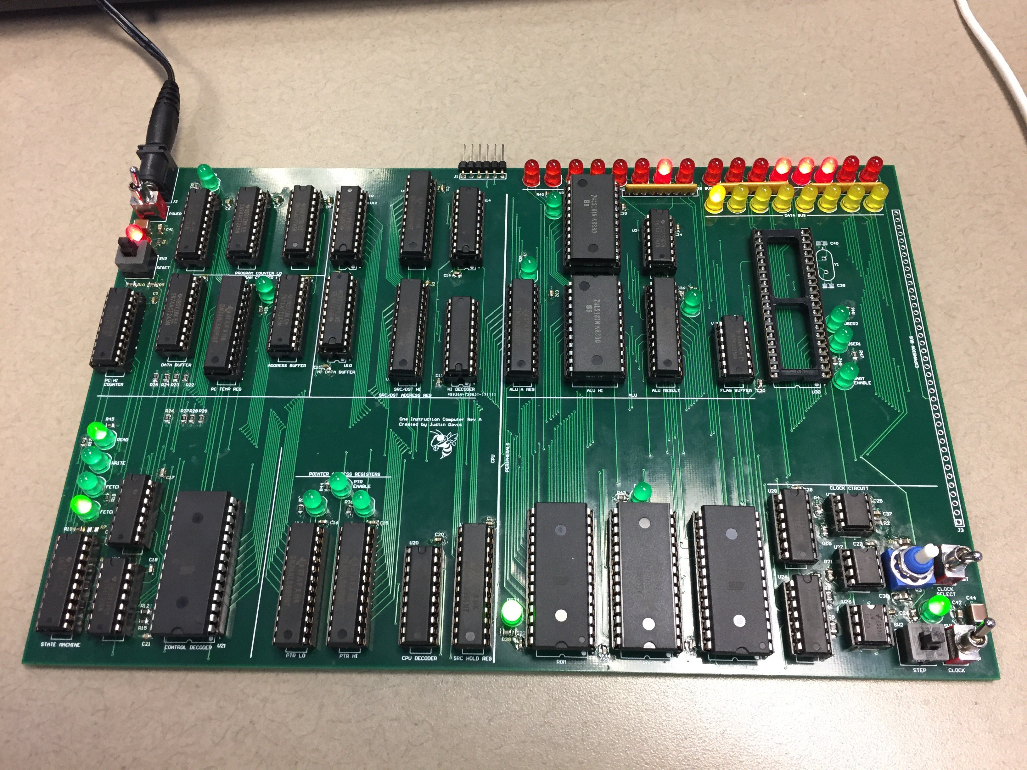
    I've made quite a bit of progress building the board.  I fixed the reset issue by changing the load state of the shift register by remove two resistors and changing one to a pull-down.  I soldered on a capacitor to filter the BREAK signal, but I haven't checked if it's too much filtering and disables the functionality at a high clock speed.

    I added the instruction ROM, and found another bug.  I needed to bring the most significant bit of the address bus into my control ROM decode to disable the ROM when the RAM is being accessed.  Just one more jumper wire.

    I added the Source/Destination circuitry and found another bug.  I have an enable for either the SRC/DST address or the pointer address.  It doesn't disable the output to the memory address bus correctly, but fortunately I have an extra AND gate which I can use to fix it.  But it's one more cut trace and three more jumper wires.

    I also didn't update my decoding of the pointer address, so my new address for the pointer data is 0x0004 (it was 0x000B).  Not a big deal, I just have to update my constants in my include files.

    I guess this is the price I pay for not prototyping it on a solderless breadboard, but these problems are not huge (yet).  

  • Clock gating

    Justin Davis11/30/2017 at 18:56 0 comments

    I should really learn to follow the most basic of guidelines when it comes to digital design.  One of the biggest is "don't gate the clock" which I totally did.  The BREAK output from my ROM is glitching which causes the clock to glitch high for about 200ns.  This causes some chips to clock and some don't.  I can even force this output low on all ROM values, and it still glitches high.  So I can short-term fix this by putting a capacitor on this pin.  Long term I should redesign my clock circuitry and do it right.  But I'm going for short-term fixes for now.

    I've also found my reset scheme is even more annoying in that it is synchronous to my control circuit, and asynchronous to my program counter chip.  And then I forget that my control circuit is wired to take an extra clock cycle on startup, but the program counter does not.  So the first instruction will execute at address 0x0001 instead of 0x0000.  I'd prefer to have the first instruction be at 0x0000, so I'm going to try to fix it.  I just have to clock the control logic once and then reset without clocking, and everything is in step.  Again, not a long term solution, but it will work in the short term.

    Annoying!

  • Crazy 60Hz noise

    Justin Davis11/29/2017 at 14:56 0 comments

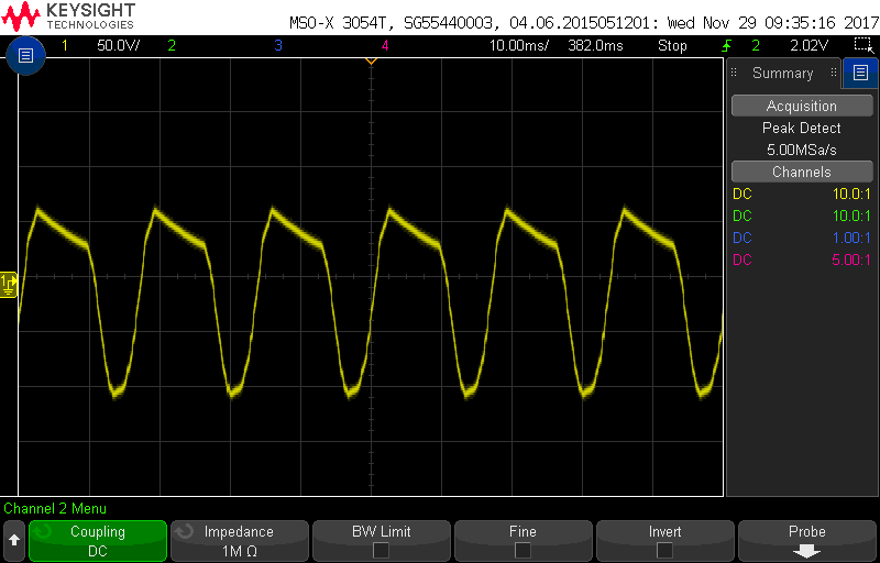
    After getting my control shift register working, I noticed it's very glitchy and would race whenever the clock was low.  After some investigation, I found this on my board.

    Not just a little 60Hz noise, but almost 150V of it.  I traced it back to my 5V wall-wart.  This picture is the ground on the wall-wart when it's disconnected from my circuit.  I have about 300uF of bypass on my board, but it can't mitigate this.  I have to imagine this is a bad wall-wart.  It's a Volgen model from Kaga Electronics made in China, but I bought it from Digikey, so I figure it's not counterfeit.  It's possible I fried it at some point, but I haven't noticed any events.  And it still measures 5V on a Fluke meter.

    I connected my board up to a good adjustable lab supply and the problems stopped.  I measured it the same way with the same scope to make sure it wasn't a scope problem (but the glitchy behavior indicates it is not).  I would still like to have a dedicated supply, so I may order another brand from Digikey.  Has anyone else had similar problems with wall-warts?

  • Clock/Control

    Justin Davis11/28/2017 at 14:23 0 comments

    I got my parts in hand, and finished the clock circuitry.  Everything works as expected there.  However, I have to jumper my break signal to ground since it goes high when not connected to anything.  I did make a few mistakes in the silkscreen - I got my RUN/STOP labels backwards and my clock selector of FAST/SLOW backward.  Not a huge deal, but still annoying.

    I also started on my control circuit.  I found I had to have a lower value pull-down resistor on my reset line.  It was sitting around 1.4V, so it was being read as a logic high instead.   TTL has internal pull-ups, so I have to overcome that if I also want a pull-down.  

    And then I discovered that I got my read/write signals backwards.  And looking into it further, some places on the board are correct and some places incorrect.  So it's a big mess that I have to fix.  I think the root of the problem is the active level of TTL is low, and I'm very used to thinking active high.  So I got them swapped when I labelled the nets.  I'll have to start figuring what traces need to be cut and patched.  This will keep me busy for a while.

    update: I have to cut 5 traces, and run 5 jumper wires.  I have all my cuts done and 3 jumper wires in.  I'll add the other jumpers when I do those chips.  Fortunately all the jumpers are on the bottom side of the board, and all go to pins of through-hole sockets.  Not a big deal, but still annoying.

  • So far so good

    Justin Davis11/22/2017 at 16:30 0 comments

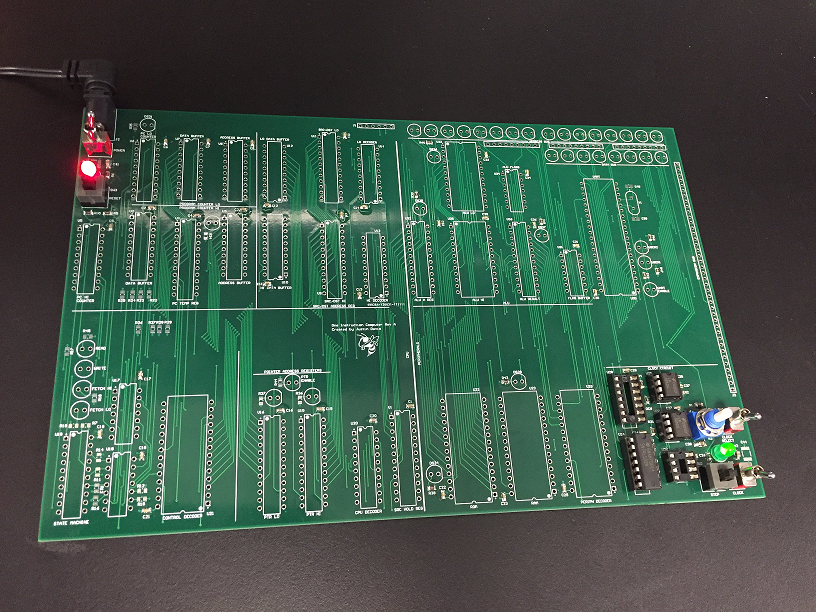
    Got the power up and running.  The clock is on, but forgot to order a couple chips.  I did not go through my BOM closely enough.  So I'm ordering some today and hopefully they will be here soon.  In the meantime I've put on other time consuming parts like all my bypass capacitors and surface mount resistors.  They need to go on first anyway so I don't melt my sockets.

  • PCBs are in!

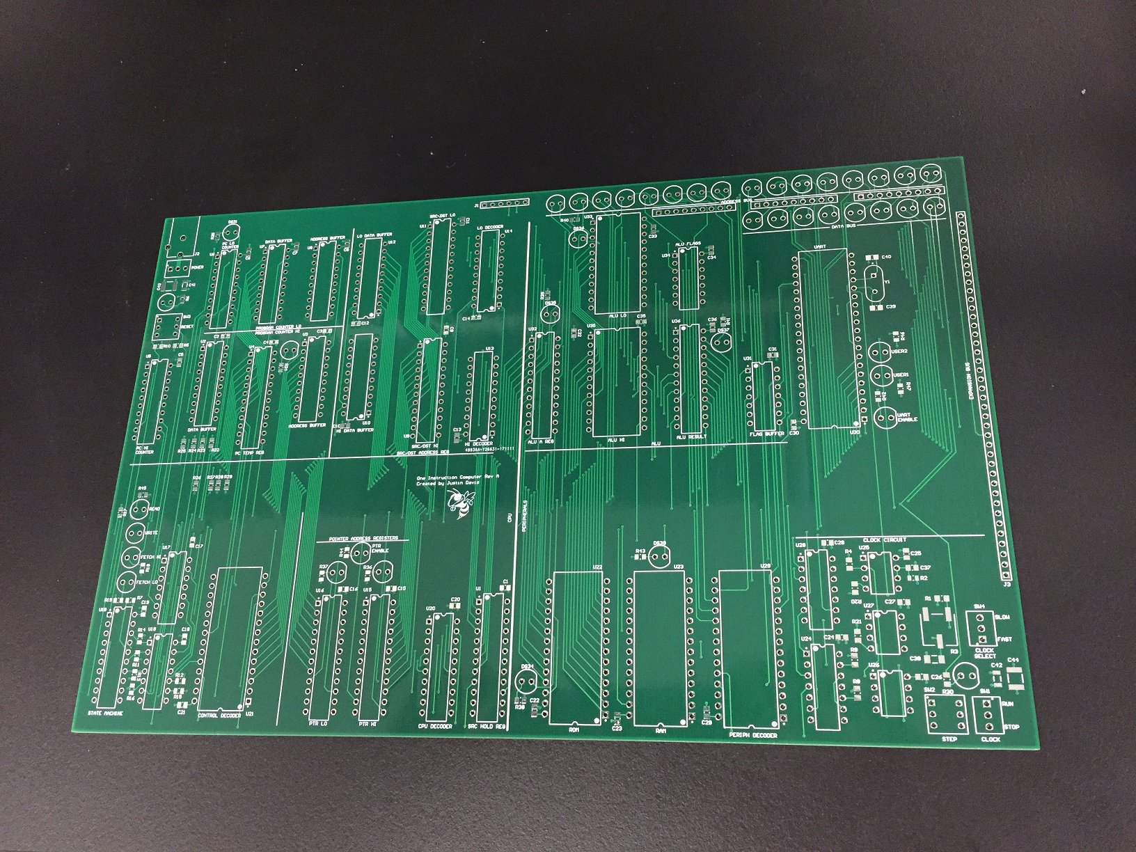
    Justin Davis11/21/2017 at 16:13 0 comments

    Now for some soldering...

  • 'LS181

    Justin Davis11/20/2017 at 18:11 0 comments

    While waiting for my boards to show up today, I was reading the front page and saw this project replicating the 74181 in low level gates:

    https://hackaday.io/project/25596-mega-one-8-one

    I also saw a note that the 74181 is no longer in production which raised a red flag for me.  I'm not sure why, but I never checked this - I always thought it was still in active production.  And so that makes me fail one of my objectives - to use only active production parts.  That's kind of disappointing, and I'm not sure why it never occurred to me.

    At some point I may start a new project for another CPU, and I will take this into account.  I really like this CPU design that spins it's own ALU which doubles as the video rendering output:

    https://hackaday.io/project/20781-8-bit-color-computer-from-ttl

    I will probably have to do something similar.  But I'm not sure what the next CPU project for me will be.  I'll finish this one first.  But I have learned a lot, and I'll know a little better next time what is reasonably available.

View all 85 project logs

Enjoy this project?

Share

Discussions

agp.cooper wrote 07/13/2017 at 15:27 point

Hi Justin,
Step back and relook at what a TTA is:
MOV [DST], [SRC] 
---
The machine cycles are:
Fetch SRC (address)
Fetch Data from [SCR]
Fetch DST (address)
Deposit Data to [DST]
This is what the timing diagram of the control signal looks like for the above machine cycle:


---
Sorry there is no load immediate but your assembler can store a constant for you to simulate a load immediate.
---
For indirect addressing (pointer to pointer moves, you will need these at some point), you will need self modifying code. 
That is for another time.
--
If your happy with the above the decoder logic is four chips including the clock.
---
AlanX

  Are you sure? yes | no

Justin Davis wrote 07/13/2017 at 15:46 point

I can see one different in our design strategies.  I've been using the same clock for all my components, but then using the enable lines to control when I want them to do something.  You send each component it's own clock only when you want it to do something.  I've found a lot of TTL components do not have enables, so this makes a lot of sense.

  Are you sure? yes | no

agp.cooper wrote 07/13/2017 at 08:38 point

Hi Justin,

After 56 logs and frustrated by the load instruction do you want some help?

AlanX

  Are you sure? yes | no

Justin Davis wrote 07/13/2017 at 11:48 point

I'm always open to advice.  The load instruction only became a problem when I decided to combine the source and destination buses into one.  It removed like 6 chips, but had to add two back.  So it's not a huge deal - just optimizing the design.

  Are you sure? yes | no

Andrew Starr wrote 04/28/2017 at 00:39 point

Very interesting! TTA has a certain austere simplicity that appeals....

  Are you sure? yes | no

agp.cooper wrote 04/25/2017 at 08:43 point

Hi Justin,

Have a look my Weird CPU it is a true move only CPU build with TTL:

https://hackaday.io/project/12879-weird-cpu


It is a lot more primitive than what you are proposing.

Regards AlanX

  Are you sure? yes | no

Justin Davis wrote 04/25/2017 at 21:53 point

That looks great! And gives me some ideas for my own project.

  Are you sure? yes | no

Justin Davis wrote 04/22/2017 at 11:27 point

well that takes the wind out of my sails a bit.  I may have to review my goals based on these projects to keep mine unique

  Are you sure? yes | no

Yann Guidon / YGDES wrote 04/22/2017 at 13:36 point

no, just continue in your own way, you can only make something unique and discover new ideas if you don't look too much at other things :-)

  Are you sure? yes | no

Justin Davis wrote 04/22/2017 at 17:29 point

Ya, looking over that project and a few others, I still think my direction is unique. I think the one posted today is not a true one-instruction since it decodes the instruction into 4 different functions even taking a different number of clock cycles for each instruction. The others handle branches differently from how I'm planning on doing it. But they did have some good ideas.

  Are you sure? yes | no

Similar Projects

Does this project spark your interest?

Become a member to follow this project and never miss any updates