-
Revisited architecture
01/10/2020 at 20:56 • 1 commentI've been thinking about this project lately which I eventually got working, but wasn't completely satisfied with it since I didn't technically complete the project goals. Specifically, the 74181 chip is obsolete. My goal was not to use any obsolete chips. Not sure why I didn't see that from the start.
I've been reviewing other people's projects and have learned how to do ALU functions without an ALU. It comes down to implementing an 8-bit lookup table in ROM for adding one to a byte. Each memory location is just one more than the index. And if you can add one, then you can add any number. And if you can add any number, you can do multiplication. And if you add FF to a byte, then it's basically the same as subtracting one which will enable you to subtract any number which will enable division. Sure it will take a long time, but it is possible. So I could just remove the ALU.
Also, I could do branches more easily by using a RAM compare using indexed memory accessing. So if I want to do a BEQ then I could specify two bytes to compare JJ and KK and two memory locations to jump to QQ (equal) and PP (different).
- Write PP to the memory location 0x00JJ (yes they're backwards).
- Write QQ to memory location 0x00KK.
- Read the byte from memory location 0x00JJ and then branch to that value.
If JJ and KK are different, then I will read back PP. If they are the same, then QQ will overwrite PP and I'll read back QQ.
I may take another stab at the design for this given these techniques.
-
Memory problems
12/19/2017 at 20:54 • 0 commentsI have the UART working finally. I was not initializing all of my registers. I set the lower byte, but assumed the upper byte was reset to zero. It was not. That's one big thing I've learned about TTL - you really need to initialize everything manually. I have a simple echo program working, so next up would be the monitor/bootloader.
But I'm still not working 100% yet - the RAM is not working. But I think once I debug that, it will be 100%. I'd reallly like to get this working before Christmas - so close!
-
Mostly working (mostly)
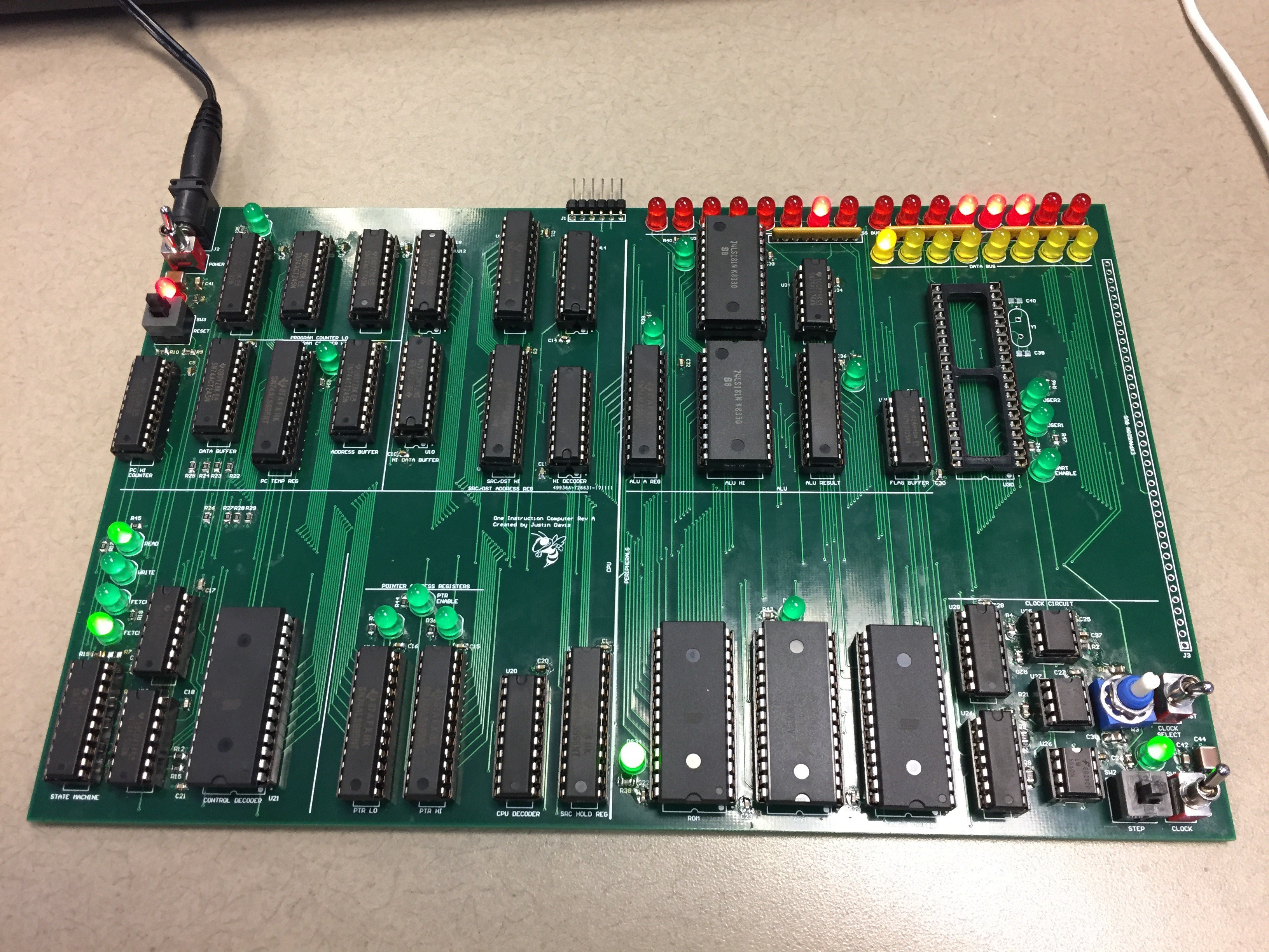
12/14/2017 at 18:42 • 0 commentsI have all of the CPU working now with the exception of the UART. My BREAK command is working, which makes it much easier to check out the functions. I just run the clock fast until it hits the BREAK command, and then I can step through the next instruction. Now, I just need to get the UART working so I can load programs over that port to the RAM directly. So close!
![]()
-
Ch-ch-ch-changes
12/05/2017 at 19:30 • 0 commentsI've made quite a bit of progress building the board. I fixed the reset issue by changing the load state of the shift register by remove two resistors and changing one to a pull-down. I soldered on a capacitor to filter the BREAK signal, but I haven't checked if it's too much filtering and disables the functionality at a high clock speed.
I added the instruction ROM, and found another bug. I needed to bring the most significant bit of the address bus into my control ROM decode to disable the ROM when the RAM is being accessed. Just one more jumper wire.
I added the Source/Destination circuitry and found another bug. I have an enable for either the SRC/DST address or the pointer address. It doesn't disable the output to the memory address bus correctly, but fortunately I have an extra AND gate which I can use to fix it. But it's one more cut trace and three more jumper wires.
I also didn't update my decoding of the pointer address, so my new address for the pointer data is 0x0004 (it was 0x000B). Not a big deal, I just have to update my constants in my include files.
I guess this is the price I pay for not prototyping it on a solderless breadboard, but these problems are not huge (yet).
-
Clock gating
11/30/2017 at 18:56 • 0 commentsI should really learn to follow the most basic of guidelines when it comes to digital design. One of the biggest is "don't gate the clock" which I totally did. The BREAK output from my ROM is glitching which causes the clock to glitch high for about 200ns. This causes some chips to clock and some don't. I can even force this output low on all ROM values, and it still glitches high. So I can short-term fix this by putting a capacitor on this pin. Long term I should redesign my clock circuitry and do it right. But I'm going for short-term fixes for now.
I've also found my reset scheme is even more annoying in that it is synchronous to my control circuit, and asynchronous to my program counter chip. And then I forget that my control circuit is wired to take an extra clock cycle on startup, but the program counter does not. So the first instruction will execute at address 0x0001 instead of 0x0000. I'd prefer to have the first instruction be at 0x0000, so I'm going to try to fix it. I just have to clock the control logic once and then reset without clocking, and everything is in step. Again, not a long term solution, but it will work in the short term.
Annoying!
-
Crazy 60Hz noise
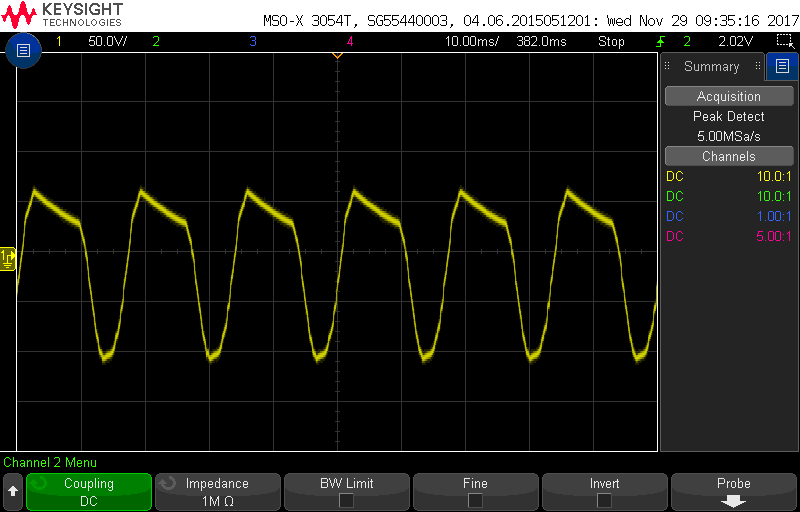
11/29/2017 at 14:56 • 0 commentsAfter getting my control shift register working, I noticed it's very glitchy and would race whenever the clock was low. After some investigation, I found this on my board.
![]()
Not just a little 60Hz noise, but almost 150V of it. I traced it back to my 5V wall-wart. This picture is the ground on the wall-wart when it's disconnected from my circuit. I have about 300uF of bypass on my board, but it can't mitigate this. I have to imagine this is a bad wall-wart. It's a Volgen model from Kaga Electronics made in China, but I bought it from Digikey, so I figure it's not counterfeit. It's possible I fried it at some point, but I haven't noticed any events. And it still measures 5V on a Fluke meter.
I connected my board up to a good adjustable lab supply and the problems stopped. I measured it the same way with the same scope to make sure it wasn't a scope problem (but the glitchy behavior indicates it is not). I would still like to have a dedicated supply, so I may order another brand from Digikey. Has anyone else had similar problems with wall-warts?
-
Clock/Control
11/28/2017 at 14:23 • 0 commentsI got my parts in hand, and finished the clock circuitry. Everything works as expected there. However, I have to jumper my break signal to ground since it goes high when not connected to anything. I did make a few mistakes in the silkscreen - I got my RUN/STOP labels backwards and my clock selector of FAST/SLOW backward. Not a huge deal, but still annoying.
I also started on my control circuit. I found I had to have a lower value pull-down resistor on my reset line. It was sitting around 1.4V, so it was being read as a logic high instead. TTL has internal pull-ups, so I have to overcome that if I also want a pull-down.
And then I discovered that I got my read/write signals backwards. And looking into it further, some places on the board are correct and some places incorrect. So it's a big mess that I have to fix. I think the root of the problem is the active level of TTL is low, and I'm very used to thinking active high. So I got them swapped when I labelled the nets. I'll have to start figuring what traces need to be cut and patched. This will keep me busy for a while.
update: I have to cut 5 traces, and run 5 jumper wires. I have all my cuts done and 3 jumper wires in. I'll add the other jumpers when I do those chips. Fortunately all the jumpers are on the bottom side of the board, and all go to pins of through-hole sockets. Not a big deal, but still annoying.
-
So far so good
11/22/2017 at 16:30 • 0 commentsGot the power up and running. The clock is on, but forgot to order a couple chips. I did not go through my BOM closely enough. So I'm ordering some today and hopefully they will be here soon. In the meantime I've put on other time consuming parts like all my bypass capacitors and surface mount resistors. They need to go on first anyway so I don't melt my sockets.
-
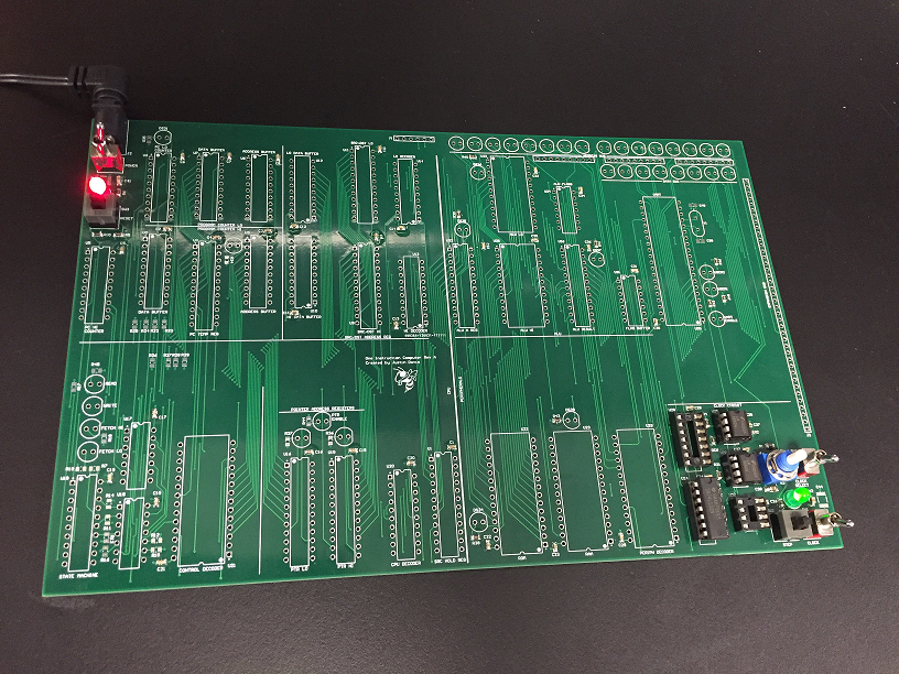
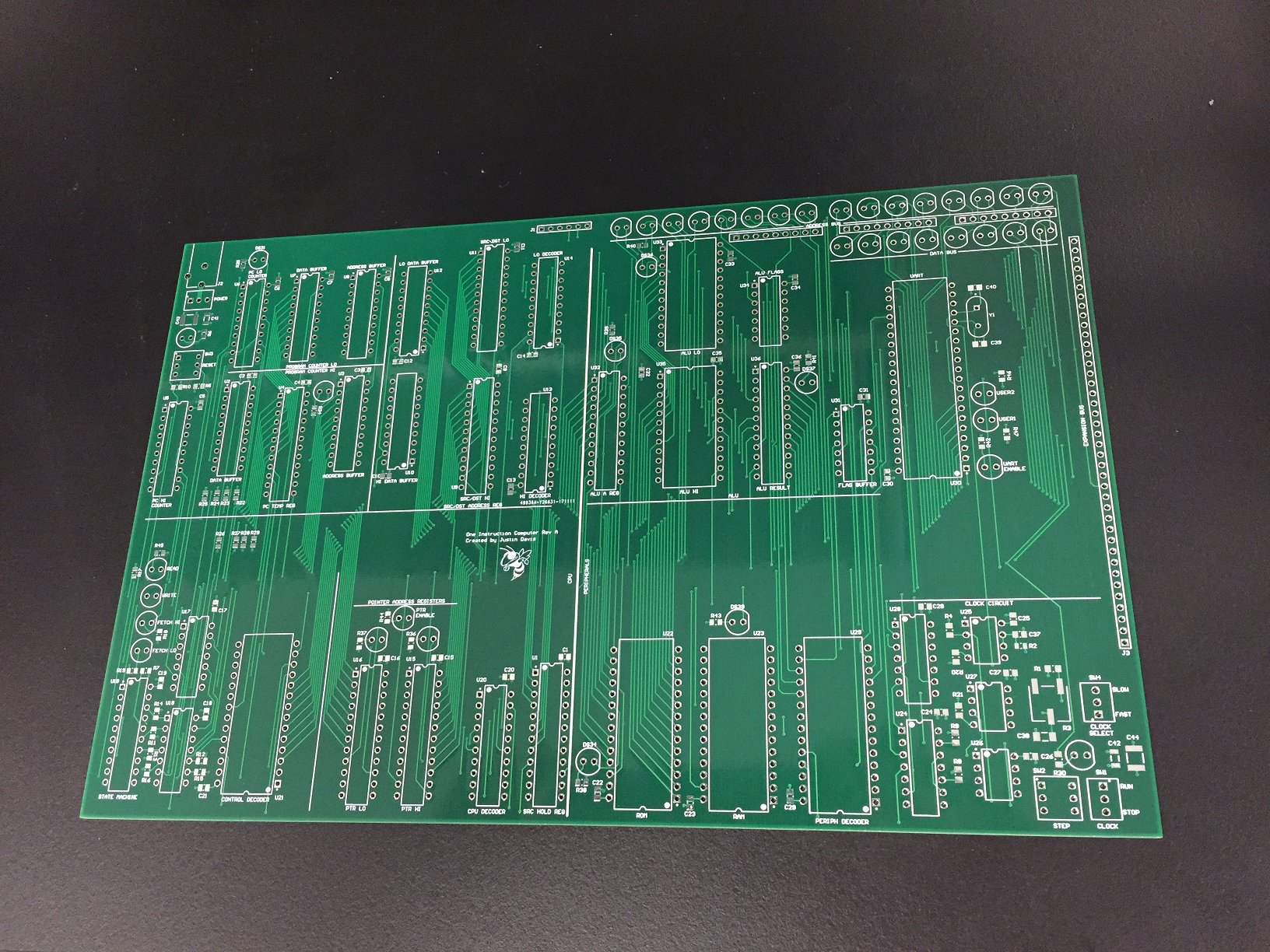
PCBs are in!
11/21/2017 at 16:13 • 0 commentsNow for some soldering...
-
'LS181
11/20/2017 at 18:11 • 0 commentsWhile waiting for my boards to show up today, I was reading the front page and saw this project replicating the 74181 in low level gates:
https://hackaday.io/project/25596-mega-one-8-one
I also saw a note that the 74181 is no longer in production which raised a red flag for me. I'm not sure why, but I never checked this - I always thought it was still in active production. And so that makes me fail one of my objectives - to use only active production parts. That's kind of disappointing, and I'm not sure why it never occurred to me.
At some point I may start a new project for another CPU, and I will take this into account. I really like this CPU design that spins it's own ALU which doubles as the video rendering output:
https://hackaday.io/project/20781-8-bit-color-computer-from-ttl
I will probably have to do something similar. But I'm not sure what the next CPU project for me will be. I'll finish this one first. But I have learned a lot, and I'll know a little better next time what is reasonably available.
One-instruction TTL Computer
A breadboard-able computer which uses only a single instruction - MOVE