Close
0%
0%

[ModAir] Monochrome LCD Modules

A LCD graphic / character display module for the ModAir project

Similar projects worth following
This module interfaces a monochrome LCD display to the ModAir CAN bus. It features graphical widgets that can be added to a home screen, and linked with any sensor attached to the CAN bus. A rotary encoder is used as an interface for the user.

This module is a sub-system of the ModAir project. Refer to the main project page for details: https://hackaday.io/project/19325

Overview

The diagram below provides an overview of the module:

Features:
  • Supports most monochrome parallel LCD display modules
  • Remote console access to other modules
  • Pilot notes and checklists
  • CAN-bus debug view
  • Multiple home-screens with user defined text and graphic widgets, linked to specified sensor parameters

Schematic and PCB

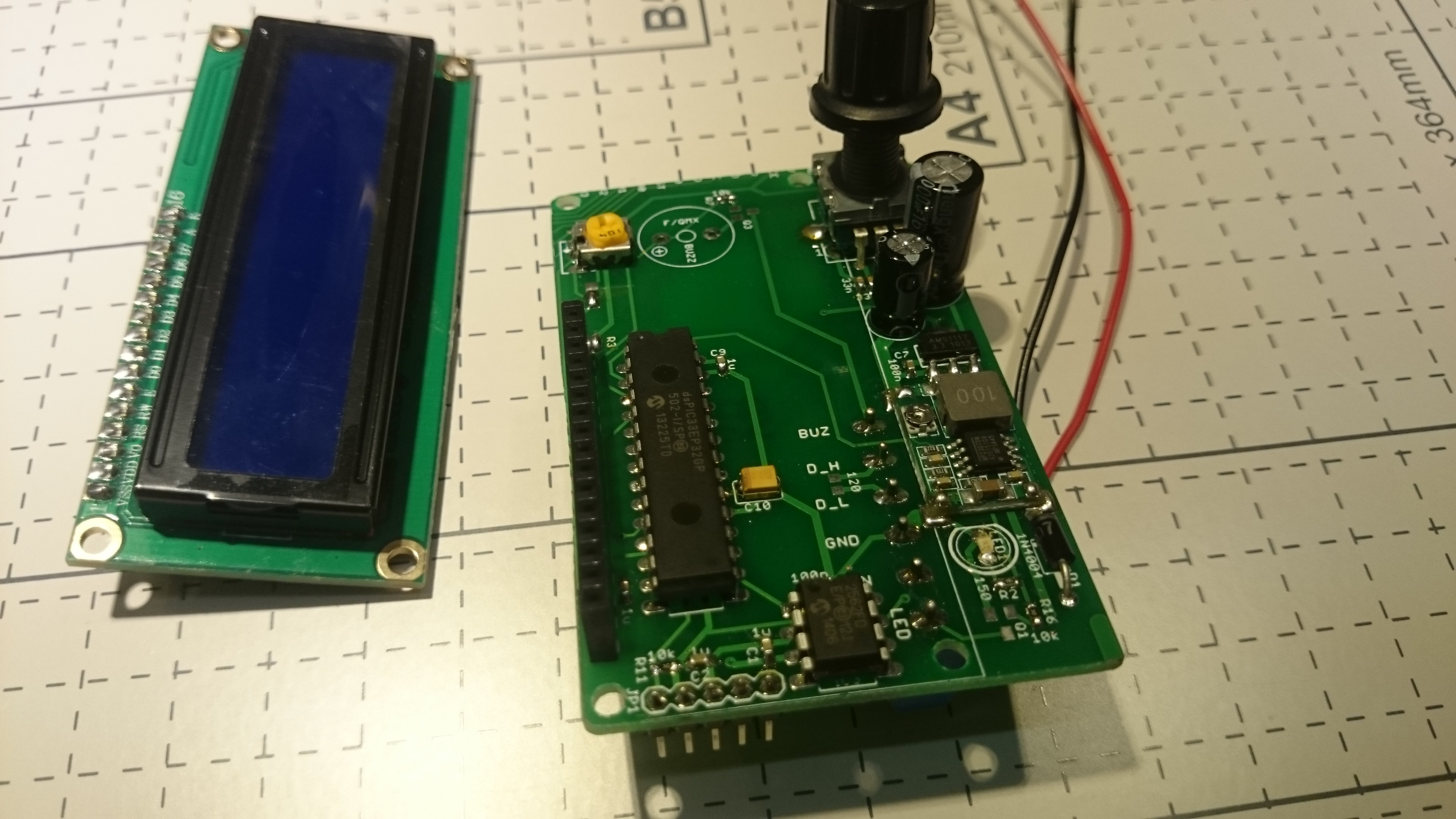
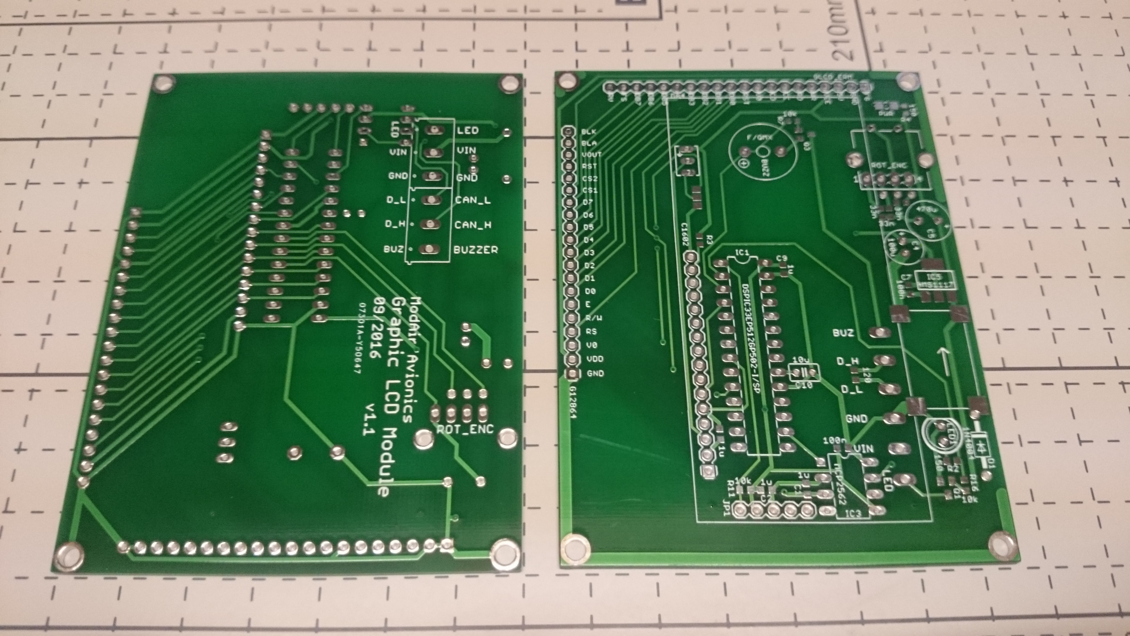
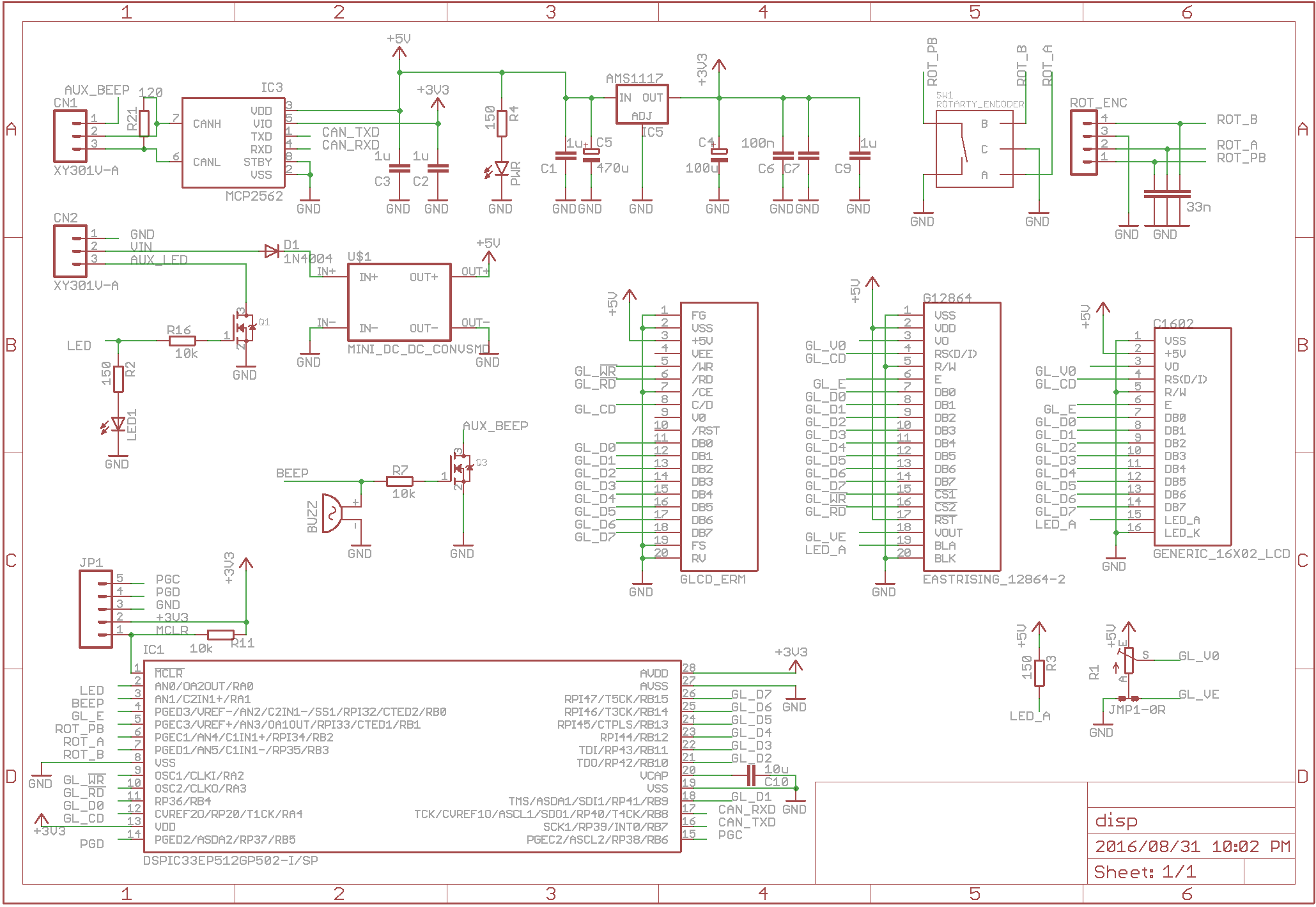
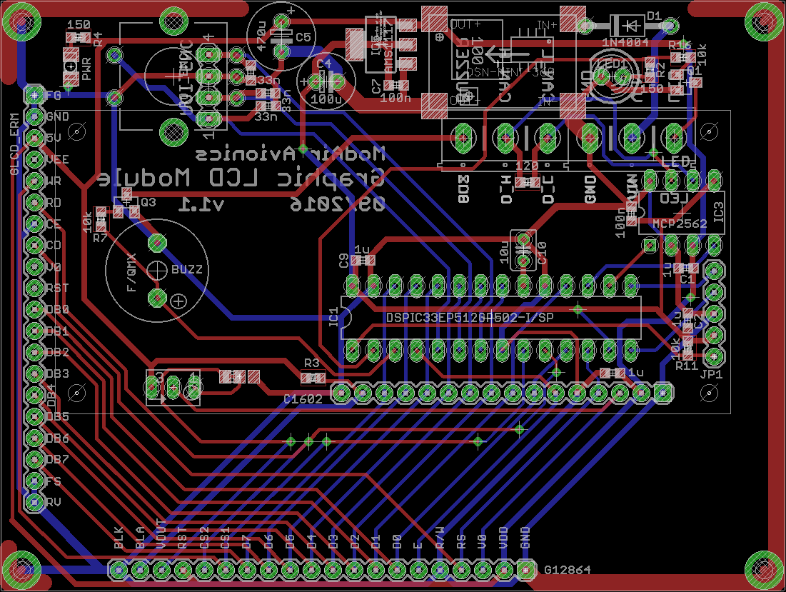
The schematic consists of a micro-controller, CAN transceiver, 5V switching regulator, 3.3V linear regulator, led, buzzer, rotary encoder interface, and three header pin rows for various LCD pin-outs.The PCB was designed to mechanically mate with some of the more common graphic and character LCDs. The following screens are recommended:
  • Nelytech NT-G128641A. Black pixels on a grey background with white backlight, 128x64 dots (currently in my microlight)
  • EastRising ERM12864FS-6. Black pixels on a grey background with white backlight, 128x64 dots (equivalent, not tested)
  • AliExpress 1602. Dark pixels on yellow green background with green backlight, 2x16 characters (equivalent to the character one below, but STN positive instead of negative, not tested)
  • AliExpress 5V 12864. Dark pixels on yellow green background with green backlight. 2.9 inch, 128x64 dots (equivalent to the one tested below, but STN positive instead of negative, not tested)

The following screens have been tested but are NOT recommended (not sunlight readable or discontinued):

  • Nelytech NT-G1286411A. White pixels on a blue background with blue backlight, 2.9 inch, 128x64 dots
  • EastRising ERM25664SBS-1. White pixels on a blue background with blue backlight, 5.8 inch, 256x64 dots (discontinued, not easily sunlight readable)
  • AliExpress 1602. White pixels on a blue background with blue backlight, 2x16 characters (white pixels are not sunlight readable)
  • AliExpress 5V 12864. White pixels on a blue background with blue backlight, 2.9 inch, 128x64 dots

Other LCD modules might not fit into the brackets, but are also possible with a ribbon cable.

  • 1 × dsPIC33EP512GP502 Microprocessors, Microcontrollers, DSPs / Microcontrollers (MCUs)
  • 1 × QC12864B 3.0" Graphic LCD Module 128x64, White on Blue, PCB size: 93x70 mm
  • 1 × ERM25664 5.8" Graphic LCD Module 256x64, White on Blue, PCB size: 184x75 mm
  • 1 × 1602 HD44780 LCD 16x2 Character LCD Module, White on Blue, PCB size: 80x36 mm
  • 1 × NT-G128641A 2.9" Graphic LCD Module 128x64, Black on White, PCB size: 93x70 mm

  • Update: 30 April 2017

    Rene04/30/2017 at 20:25 0 comments

    Current hardware status: all peripherals have been tested and work as expected. The following LCD modules have been tested and work:

    • ERM25664 256x64 monochrome (White on Blue)
    • Nelytech NT-G128641A 128x64 monochrome (Black on White)
    • Generic QC12864B 128x64 monochrome (White on Blue)
    • Generic 1602A 2x16 character monochrome (White on Blue)

    Current firmware status: about 40% complete. So far only the functionality for listing attached modules and their parameters as well as accessing any of the remote console menus has been implemented on the Nelytech LCD. The identical code should be re-usable for the other graphic LCD modules, by simply replacing the glcd.c/h files with the appropriate driver. Widgets and their configuration menus still need to be implemented.

  • First Batch: Assembled Modules

    Rene04/20/2017 at 13:26 0 comments

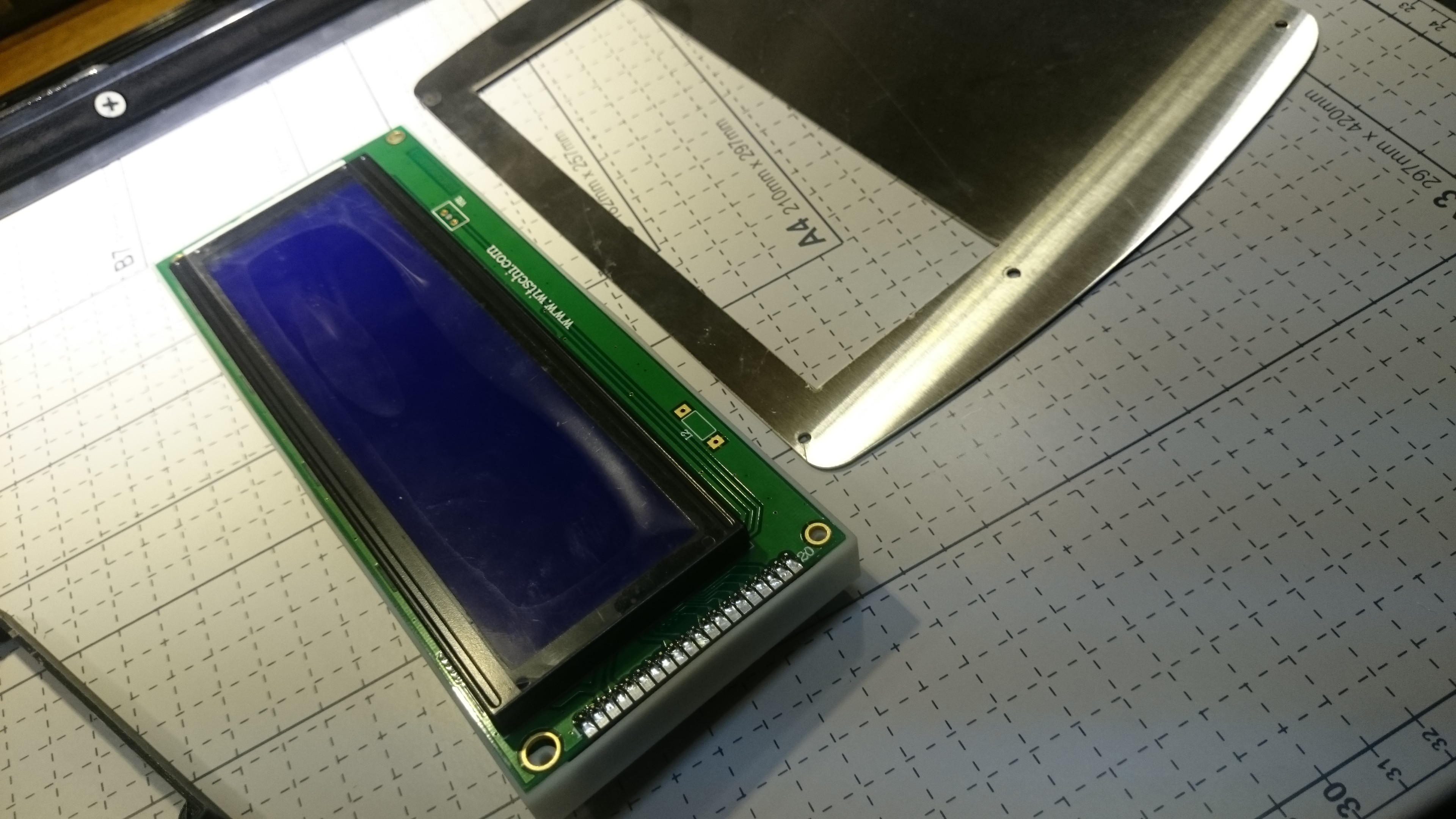
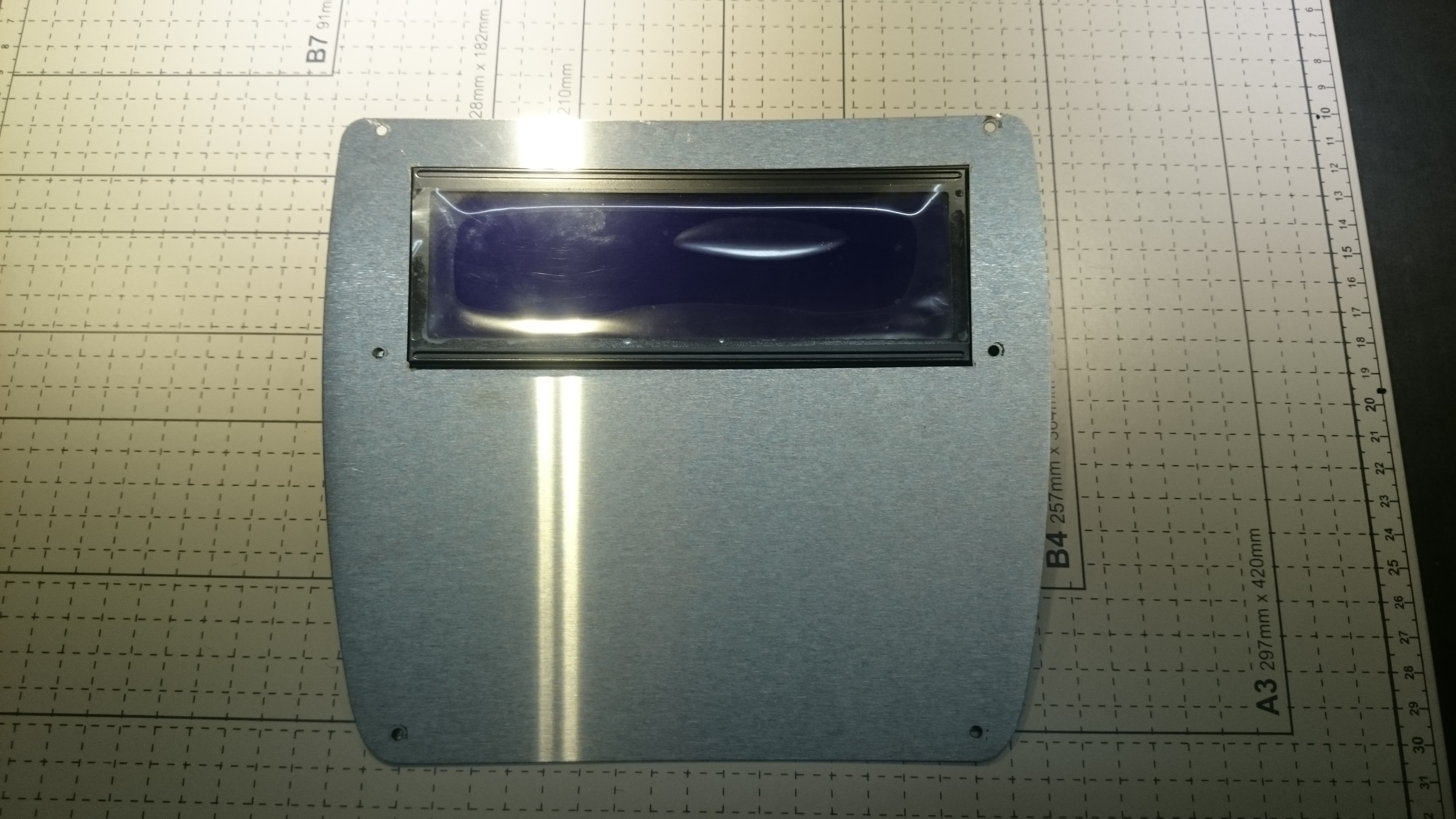
    The idea with the controller and LCD sandwiches is to mount them directly behind a front panel. I had a front panel cut from 0.9 mm brushed stainless steel (about $10 from a local metal manufacturing company), but unfortunately I only discovered the scratches underneath the protective plastic when I got back home.

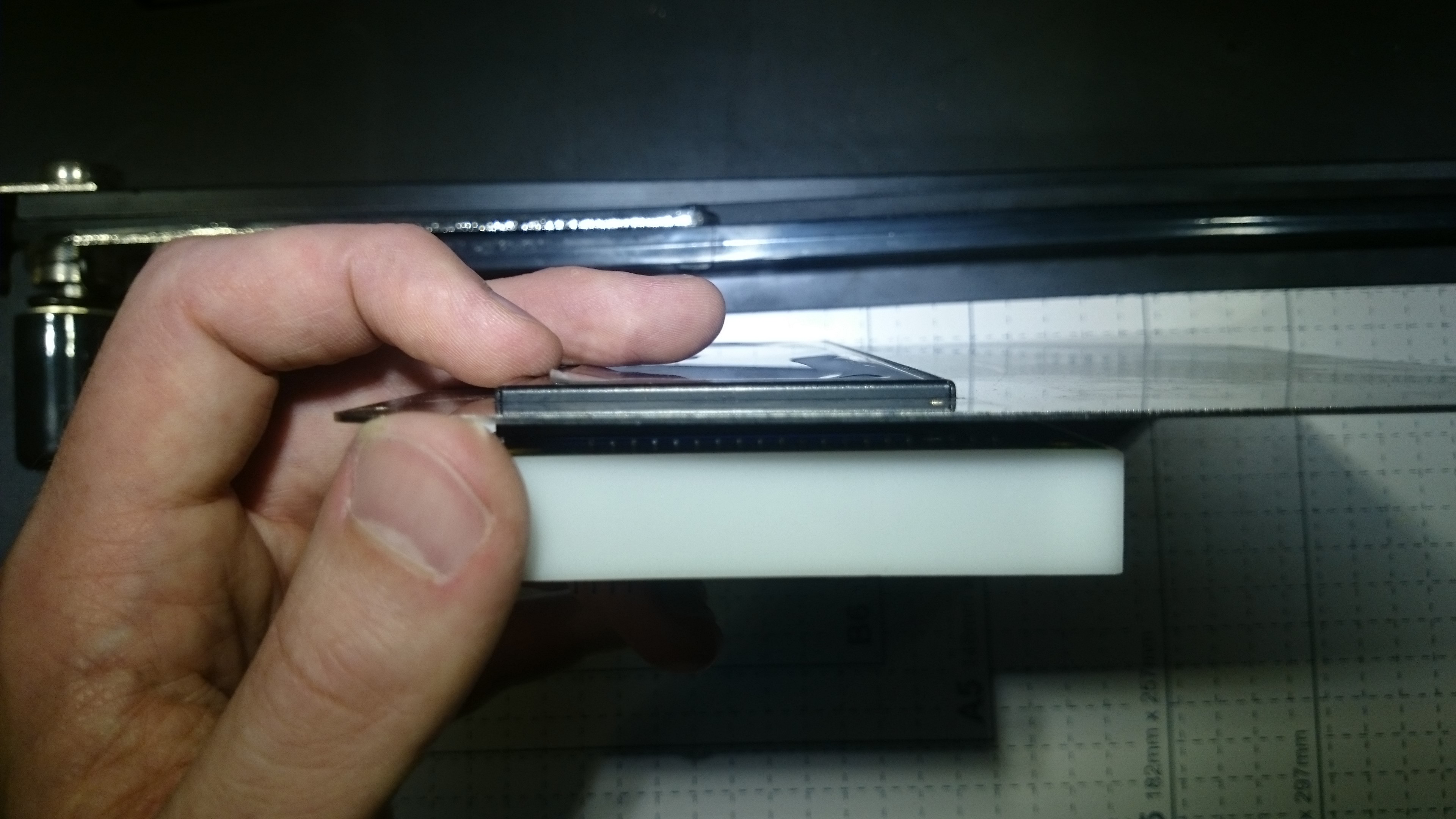
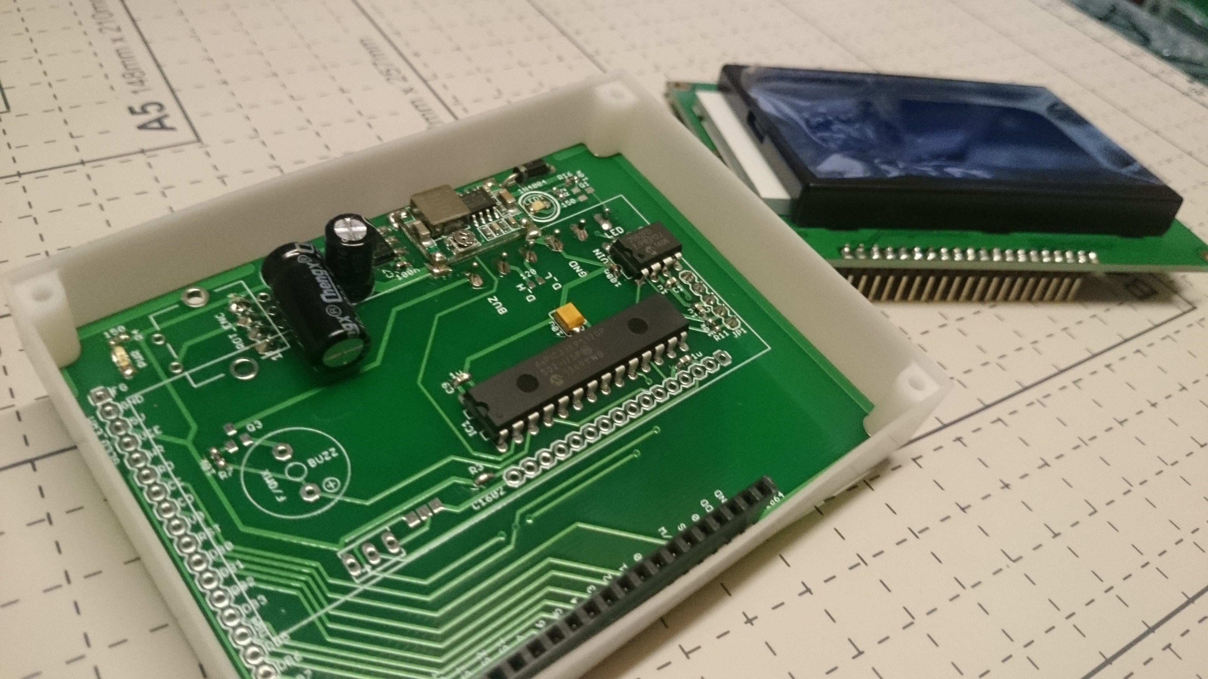
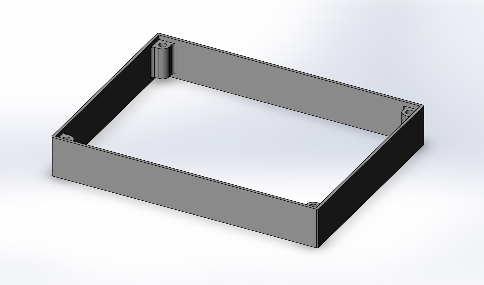
    The 3D printed brackets worked perfectly, and aligns nicely with the PCBs on both sides. In the design files I added 0.2 mm on all sides.

    For the 1602 LCD, the PCB is cut smaller with a hacksaw. For this module, the rotary encoder is mounted on the base PCB (rather than being attached with a ribbon cable).

  • First Batch: PCBs

    Rene04/20/2017 at 12:45 0 comments

    The first batch (qty10) of PCB's arrived from ITEAD.

  • 3D printed brackets

    Rene04/20/2017 at 07:31 0 comments

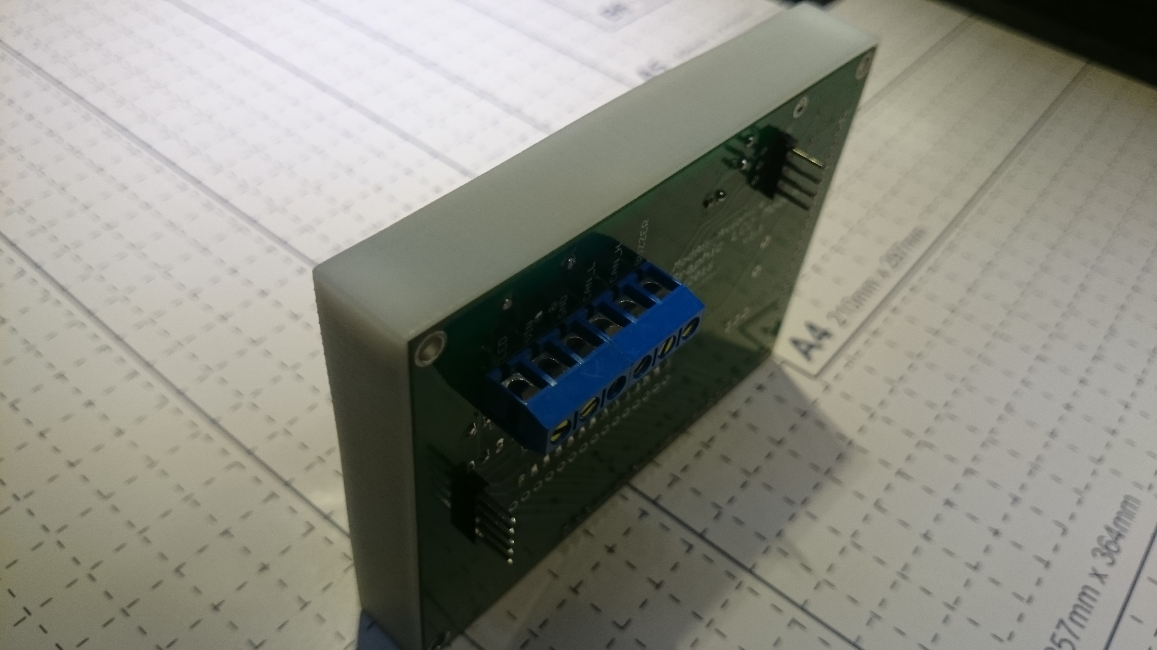
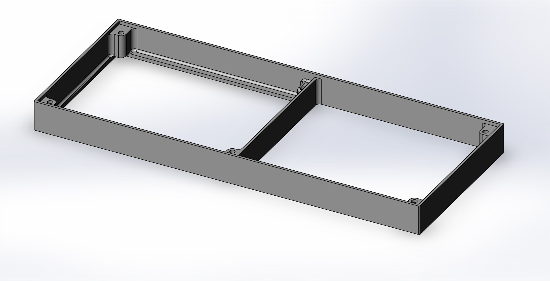
    I designed some supporting brackets to sandwich the LCD Module to the PCB. Standard 0.1" female header pins were used on the PCB side, with the male header pins on the LCD side. This brings the PCB separation to 11.0 mm. With 1.6 mm PCB thickness on both sides, the resulting stack is 14.2 mm thick.

    For the 93 x 70 mm LCDs:

    For the 184 x 75 mm LCD module:

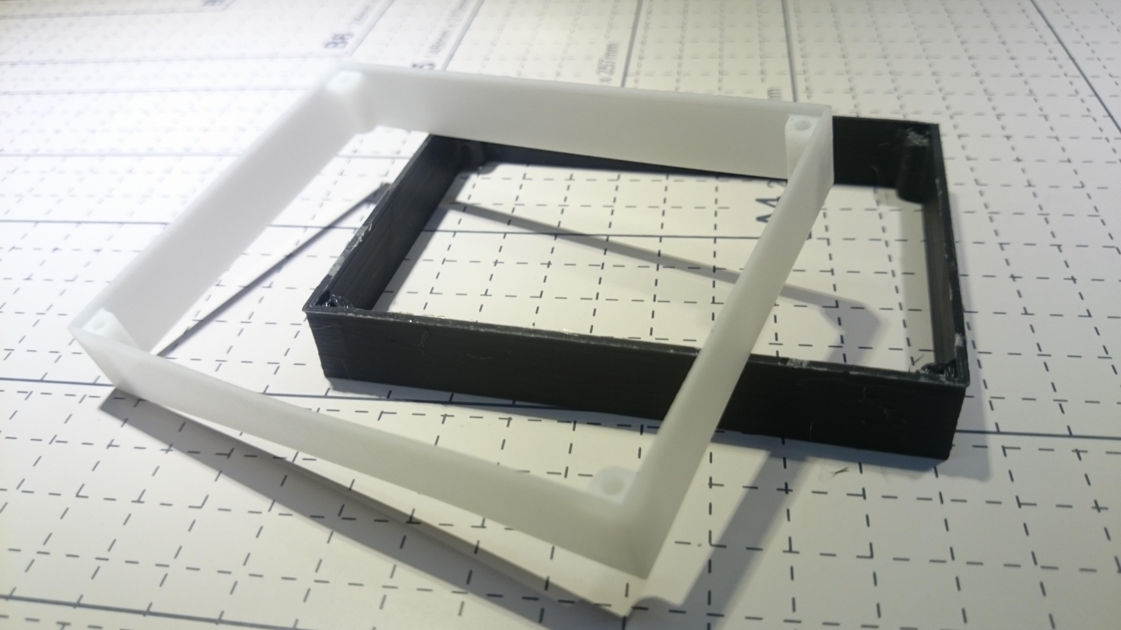
    I am quite impressed with the ITEAD SLA 3D printed parts (white parts in the pictures). There is a huge difference in quality between the SLA and the standard additive manufacturing (black ABS parts) prints.

    Even though both prints used the same design files, the black brackets seemed to have shrunk and will need some filing to fit the PCBs and LCDs...

View all 4 project logs

Enjoy this project?

Share

Discussions

Similar Projects

Does this project spark your interest?

Become a member to follow this project and never miss any updates