patchartrand
-
Electronics Build
07/24/2017 at 02:33 • 2 commentsOut of all the things to build this one is the most challenging for me. I have very little experience with building electronics. So I did what everyone in my situation would do and watch all the you tube on this subject. (to youtube's credit, there is lots of good content). I set out to design a brushed ESC that can handle the following power:
- 30A Continuous
- 24V max voltage
- Current sensing
- Temperature sensing
- Arduino bootloader
- Power output for case fan
- Header for users to expand upon if they want to
So with all those things on my design list, I set out to design version 1.0 of this controller. At first I used the VNH2SP30-E-1. This is a real nice chip because it dose quite a bit of the hard work for you since it is an all in one package (current sense, over temp shut off etc.). BUT when I went to buy the chip it had said that it was being discontinued.... So I switched to the VNH5019A-E. This chip is basically the same thing except it handles higher voltages and is not being discontinued. Below is a srceen shot of the final board design:
AAAANNNNDDDD just before I sent the gerber files to the board company.... I find out that If i double up the VNH5019A-E chips, they cannot use the current sense. SO, this was quite the setback. So then I was stuck designing the 4X mosfet setup to control a board. I was a little hesitant to control the Mosfets from an Atmel chip directly (with the gate drivers applied). This would be challenging for me and any one what would want to add in some custom code without affecting the motor controller's performance. So I did some research and found the DRV8702QRHBTQ1 from Texas Instruments. This chip takes quite a bit of guesswork out of the design. The integrated shunt resistor amplifier, boost converter gate drivers and on and on... So I put it in my circuit and I am now hoping for the best. Below is a screen shot of the completed board.
With all of the design criteria met, I sent the Gerber files to the board manufacture and ordered all the components.
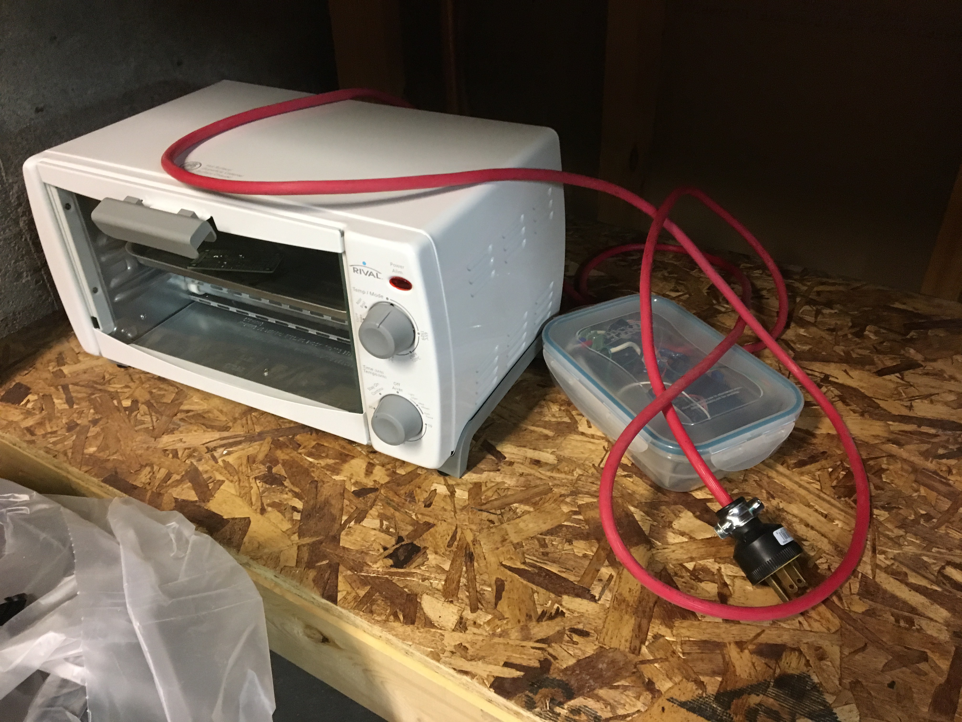
Soldering the board was real easy because I made an Arduino controlled toaster oven to reflow the solder. My first board went well except for the fact that I oriented the micro controller the wrong way and the pins for the motor controller chip had some shorts in it because I did not position it close enough. So I then proceed to make another board to correct all my mistakes. With a now freshly solderd board, I flashed the arduino boot loader (real impressed that it worked first shot) and then procedded to connect the battery..... The smoke came out of the board.... I put the leads on reverse polarity. this forced me to go back to the spread sheet of the chip and then I found some other design problems that could let the smoke out. I then assembled a third (3) board this time I will power it up with a power supply (ordered it last week) as to limit the current. I also bypassed the reverse polarity mosfet as it does not do anyting right now AND it may cause another unforseen problem. So whenever I get the power supply I will contunue to trouble shoot the board. Here is a picture of the latest board build complete with bypass wire instead of a mosfet.![]()
-
Mechanical Build 02
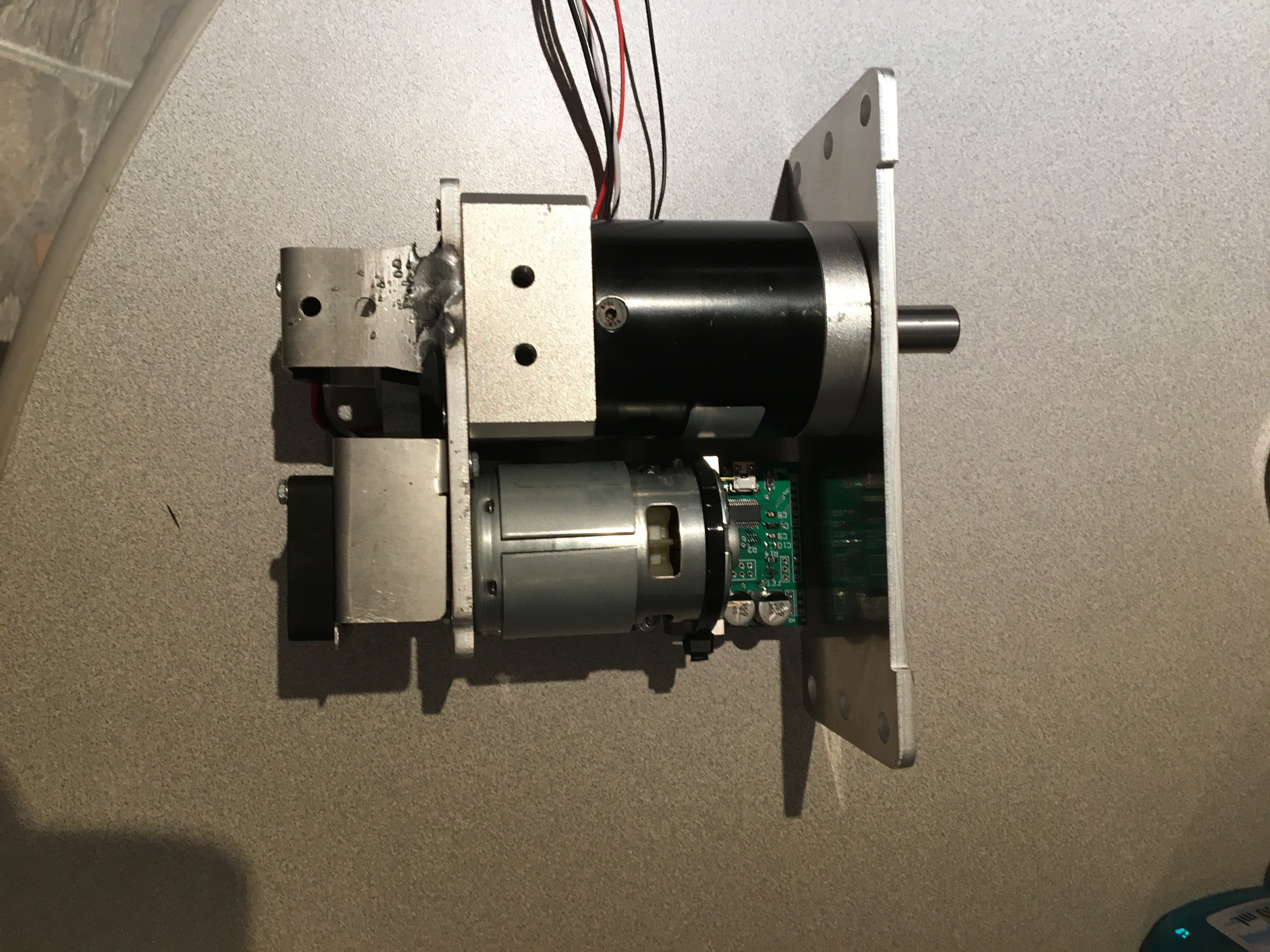
07/23/2017 at 03:19 • 1 commentOnce I bent all the metal parts, the fun Begins! I stayed up all night putting this servo together. The fit of the parts went quite well actually. The biggest problem was me not following my build plan because I was too lazy to print them.... Yes, yes I know RTFM. Now the USB port on my board is not facing out. This feature would be nice to have because I will be programming it soon enough and flashing the board will be cumbersome.
Here is the servo 1/2 assembled:
![]()
The aluminum welds are not the best but if anyone has done aluminum welding they will definitely point out that this is not for beginners (I would put myself as an intermediate).
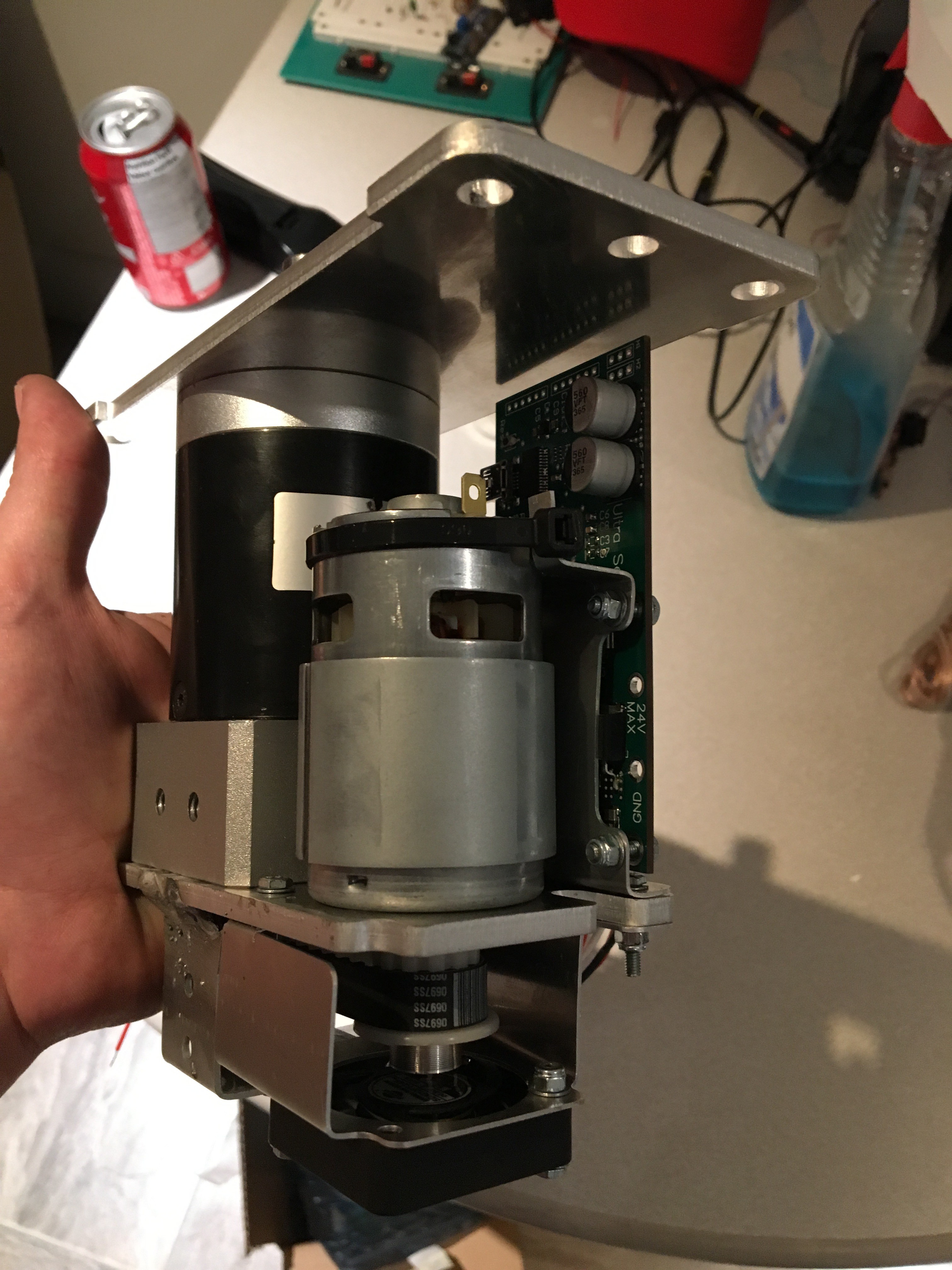
This next picture is me holding the servo so you can get a sense of scale.
![]()
Hard to believe this thing will generate 60 ft*lbs! I was real excited at this point, so I tried to explain it to my wife. It turns out that she does not have the same enthusiasm as I do.
The pulleys are press fit onto the shafts and in all fairness I was skeptical of the press fit charts but it worked like a charm. Here is website that I used to make the gearbox adapter and pulley holes:
http://www.engineersedge.com/class_v.htm
The circuit board on the servo may look good but it is not functional right now. I have started to play around with it but it was not a successful first try. I am still troubleshooting it but I hope to have an update tomorrow night. -
Mechanical build 1
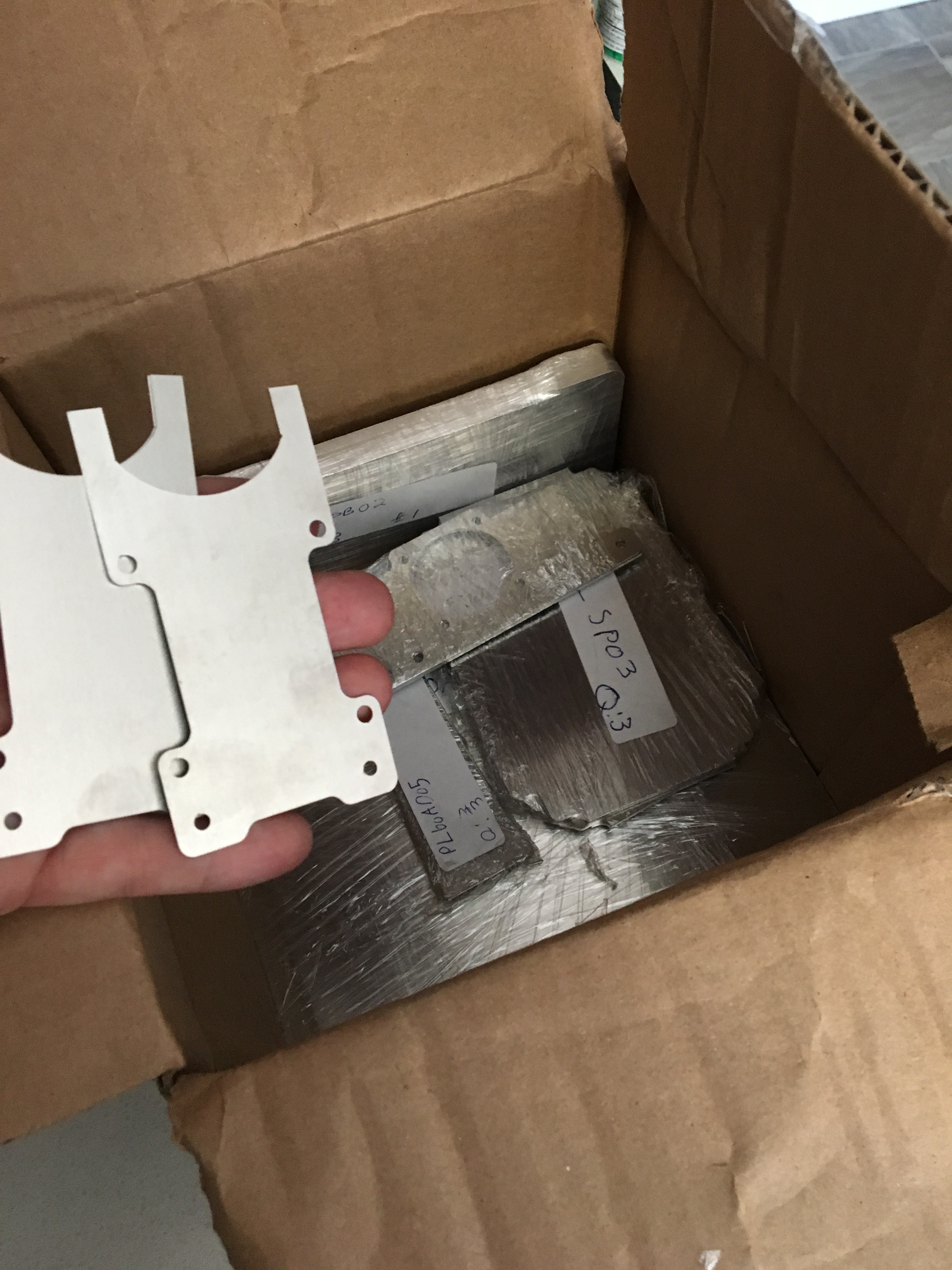
07/23/2017 at 03:02 • 0 commentsI have finally recived my laser cut parts from the CNC place. They are immaculate. I encourage anyone to send sheet metal parts to a CNC place because it is almost like 3D printing. Just send your super duper intricate parts to the cutters via CAD file and like magic it comes out perfect!
Here is a photo of the box of parts.
![]()
The next step was to bend all the parts on my vice press brake. I bought mine from princess auto and it worked quite well on the thin gauge material. Here is a link of the one that I have:
-
Parts ordered and design completed
06/12/2017 at 03:34 • 0 commentsSince I have created this project here, I have done some work to push the project from "pie in the sky" to reality.
- Built a ref flow oven to cook the custom boards
- Completed the design of the circuit board
- Completed the CAD design of the servo
- Ordered all the electronics parts from digikey
- Ordered all the mechanical parts
- Ordered the PCB board
As of today I have the PCB and electronics parts here, ready to be installed. Last week I had to tweak the arduino controlled oven to follow the heating profile better. (picture below)
If anyone wants me to show how I built the oven, please let me know I will make a write up about it.
![]()
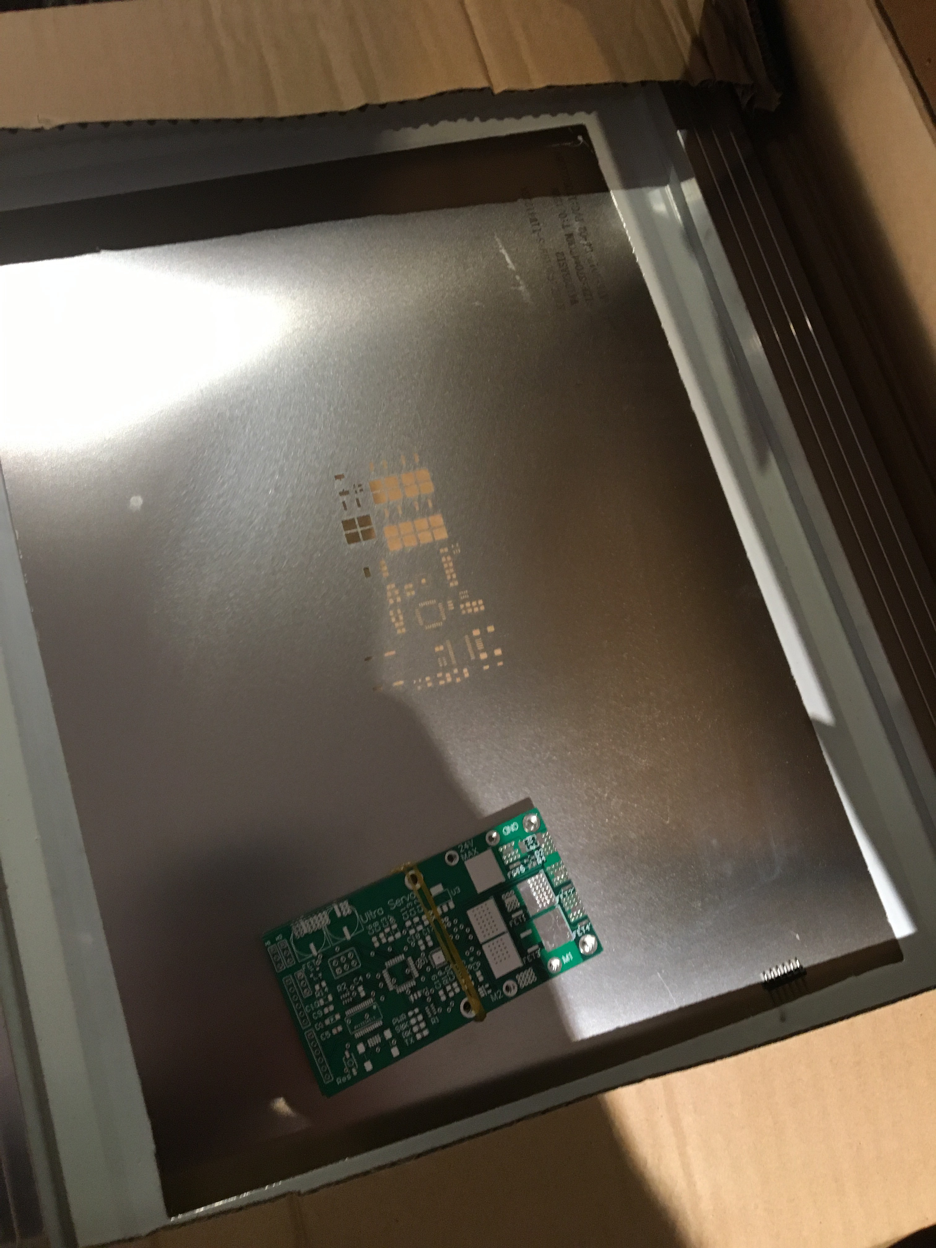
Below are some photos of the PCB and the stencil.
![]()
I am hoping to put the circuit board together this coming week to I can start programming. It is my first pcb design and build so in all fairness I have no clue how this this going to work out. I triple checked my connections, diagram and data sheets. I am sure that I commited a rookie mistake somewhere that I will find myself quite dumb for doing. But hey, you need to start somewhere right?I am sure that at the end of this there will be a log on the trouble shooting that when on to make it work.
What is left to do:
- Send the flat patterns out to the laser cutter
- bend all the pieces
- Populate the board
- Update my code to go onto the new board (that's the big one for sure)
- Build the servo
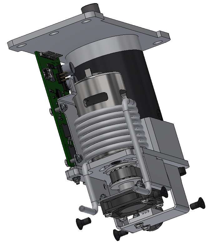
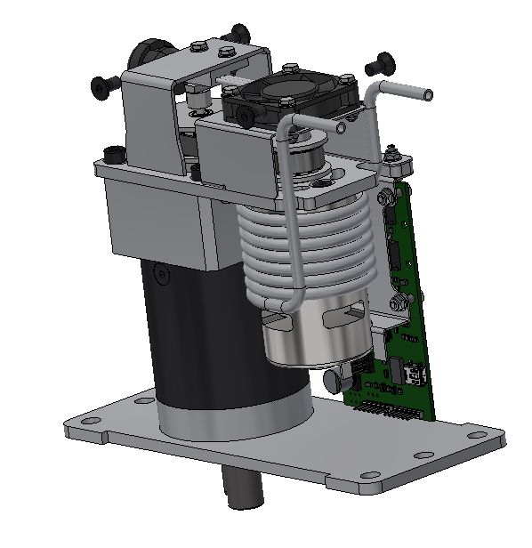
I leave you with some glamour shots of the servo's last CAD design iteration.
![]()
![]()
Ultra Servo
An ultra strong and fast servo that is reasonably priced. The goal is to generate 60ft*lbs (11 520oz*in) with 60 rpm no load rpm speed.
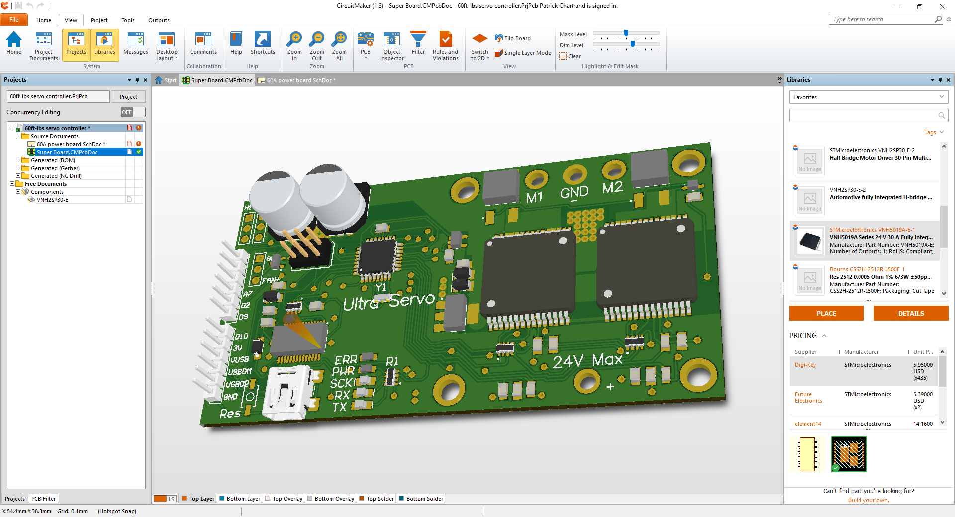 AAAANNNNDDDD just before I sent the gerber files to the board company.... I find out that If i double up the VNH5019A-E chips, they cannot use the current sense. SO, this was quite the setback. So then I was stuck designing the 4X mosfet setup to control a board. I was a little hesitant to control the Mosfets from an Atmel chip directly (with the gate drivers applied). This would be challenging for me and any one what would want to add in some custom code without affecting the motor controller's performance. So I did some research and found the DRV8702QRHBTQ1 from Texas Instruments. This chip takes quite a bit of guesswork out of the design. The integrated shunt resistor amplifier, boost converter gate drivers and on and on... So I put it in my circuit and I am now hoping for the best. Below is a screen shot of the completed board.
 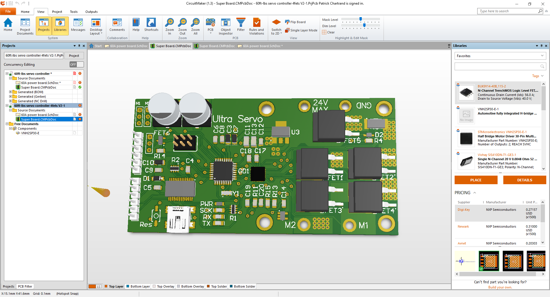 With all of the design criteria met, I sent the Gerber files to the board manufacture and ordered all the components.