Close
0%
0%

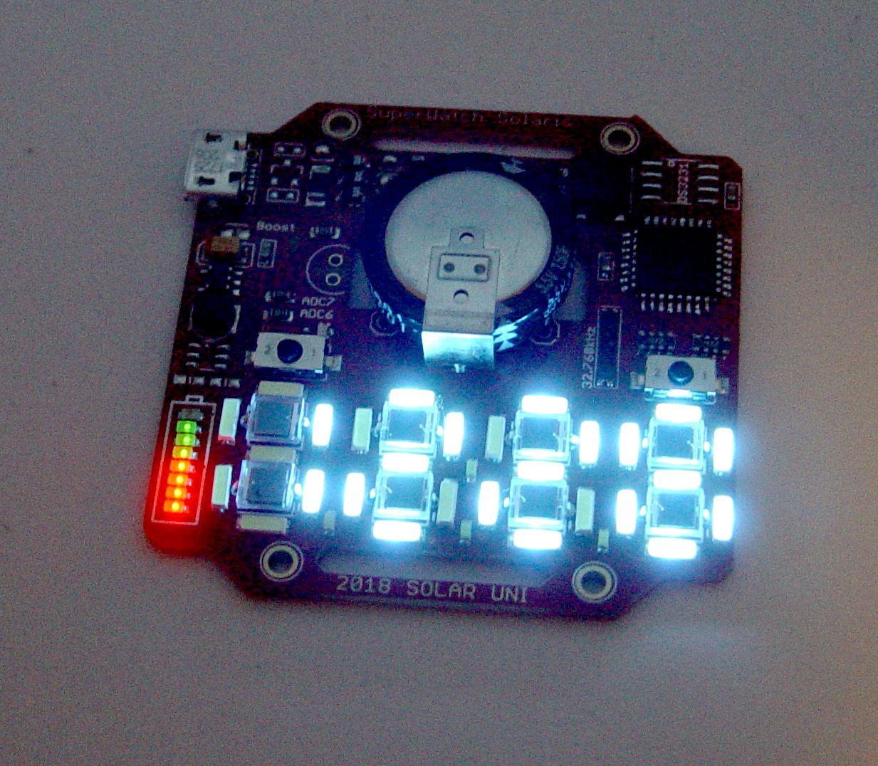
BPW34 solar powered led watch

Absolute best watch ever !!!!

Similar projects worth following
5 years of watch development in one master piece of hardware

At first big thanks Yann Guidon for eagle library for 4014 LED, and great idea with DYP LED project

I understand that this not practical watches, I calling my product

"party watch", not for daily usage but good eye catcher on special
occasions.
Standby time is acceptable, in good condition more than 7 days. If
anybody think that 5 minutes run-time is low? it is abut 300seconds if
you display time
for 3 seconds you can check time 100 times or 350 times in low brightness.

Charging:

Charging is very simple because vinatech scap are 3V, just I use 3V
fixed voltage LDO MCP1700T3002ETT with 10R resistor to limit charging
current + shottky diode
for protection reverse current to LDO .... charging voltage drop to
acceptable 2.95V

Discharging:

Heart is fixed 3V version of MAX1724 extremely low 1.5µA quiescent
supply current Step-Up DC-DC Converter which can work until 0.4V imput
voltage
I can use about 87% of stored energy. In all operation time I have
stable 3.001V for MCU.
I also have on board space for newest MAX17222 ... 300nA Iqc bu I am
unable to solder 6-Pin μDFN
Average consumption is now about 7uA.

MCU:

I am using PICOPOWER Microchip/ATMEL ATMEGA328 stanby consumption with
runing RTC is 0.9uA
Every seconds MCU wake form sleep for add second to counter and flash
led on gauge to show remaining capacity level.
If you press button you can show time, long hold adjust time ...

I am satisfied with results, I have something unique in world ... non
practical but unique ;)

supercap-wite6-NT-single-RTM.brd

brd - 236.64 kB - 07/20/2017 at 22:32

Download

supercap-wite6-NT-single-RTM.sch

sch - 1004.46 kB - 07/20/2017 at 22:32

Download

View project log

Enjoy this project?

Share

Discussions

crun wrote 09/10/2022 at 03:40 point

Totally awesome.

If you want to really extend the dark sleep life look at Ambiq 0815 RTC chips down to 14nA RTC current, and at 1.5V operation it would run direct from the BPW34's in standby. 

Using a clock output from the RTC you might be able to have a flyback convertor to bootstrap the cpu VDD, without using a dedicated power IC

  Are you sure? yes | no

Elliot Williams wrote 03/22/2018 at 09:20 point

I just noticed that you put the BPWs between the LEDs.  Brilliant!  That way the LEDs will charge themselves.  Perpetual motion!  :)

Seriously cool design.  Perhaps you've noticed that the 2018 Hackaday Prize includes an energy harvesting category.  Just saying.

  Are you sure? yes | no

Yann Guidon / YGDES wrote 03/22/2018 at 11:25 point

I just noticed too.
Awesome fit with the 3014/4014 LEDs !!!

  Are you sure? yes | no

bobricius wrote 03/22/2018 at 12:05 point

In reality it is hard readable, specially in day, segments are to far away.

Charging working only in standby on direct sunlight. there is no power for cold start microcontoller. And latest problem is that step up converter consume all power. display and MCU elat about 2mA and with step up converter 20mA. I remove step up converter and I have about 30minutes runtime on 1.5F, I adjusting brightness with pwm depend on supply voltage. Sometimes are simple solutions beter. I can decide to eat all stored power with step up converter or leave half energy unused (I can work only to 2.5V).

  Are you sure? yes | no

Jarrett wrote 12/13/2017 at 23:31 point

How do you find those solar panels? You don't mention how much power they can provide :)

Curious for all sorts of applications

  Are you sure? yes | no

drojf wrote 12/20/2017 at 11:02 point

The "solar panels" are just BPW34 photodiodes:

https://www.vishay.com/docs/81521/bpw34.pdf

  Are you sure? yes | no

Jarrett wrote 12/20/2017 at 18:05 point

Sure, but the point stands. They're being used as some sort of panel... That collects solar energy...

Plus, I need to know how sensitive it is to kappa particles

  Are you sure? yes | no

davedarko wrote 12/20/2017 at 13:23 point

I think they're also used as alpha radiation detectors. Or was it beta? Gamma even? I forgot :D

  Are you sure? yes | no

Ted Yapo wrote 12/20/2017 at 13:34 point

Gamma. Alpha and beta can't get in there.

  Are you sure? yes | no

deʃhipu wrote 12/20/2017 at 14:19 point

Theta, plus minus Epsilon.

  Are you sure? yes | no

Untitled wrote 07/20/2017 at 21:16 point

Is your PCB open source?  I have a project in mind that would re-use the solar and mpu features of your design.

  Are you sure? yes | no

bobricius wrote 07/20/2017 at 22:33 point

I uploaded board sources in to Files

  Are you sure? yes | no

bobricius wrote 04/21/2017 at 12:04 point

I am using your great library, I am not tested how leds fit (I have no one now), I ordered PCB today I hope that all work as I expect. Of course reflow only, hand soldering is night mare :)

  Are you sure? yes | no

Yann Guidon / YGDES wrote 04/21/2017 at 11:47 point

So finally you made your own 4014 footprints, but you have to oven-solder them, they are much harder to hand solder this way...

  Are you sure? yes | no

Similar Projects

Does this project spark your interest?

Become a member to follow this project and never miss any updates