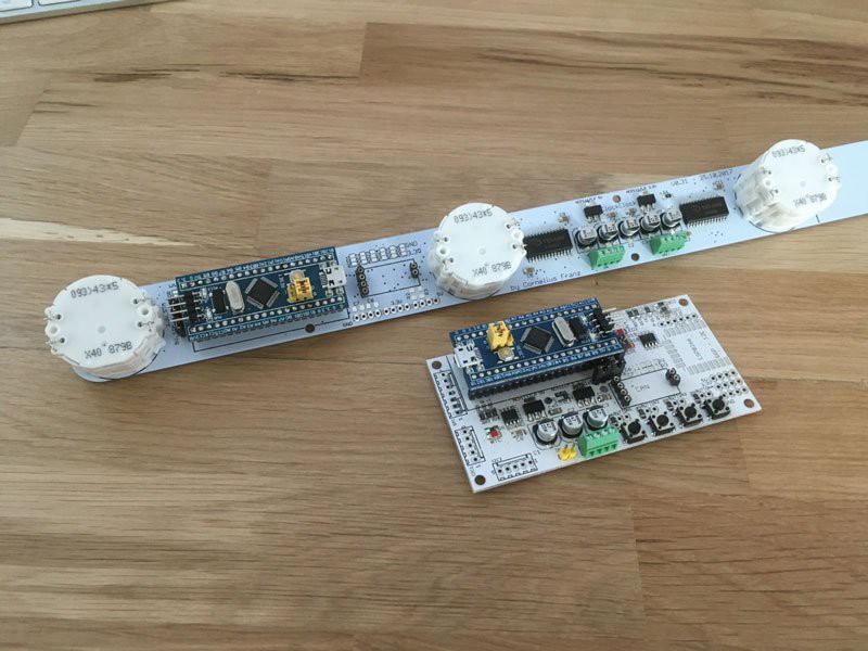
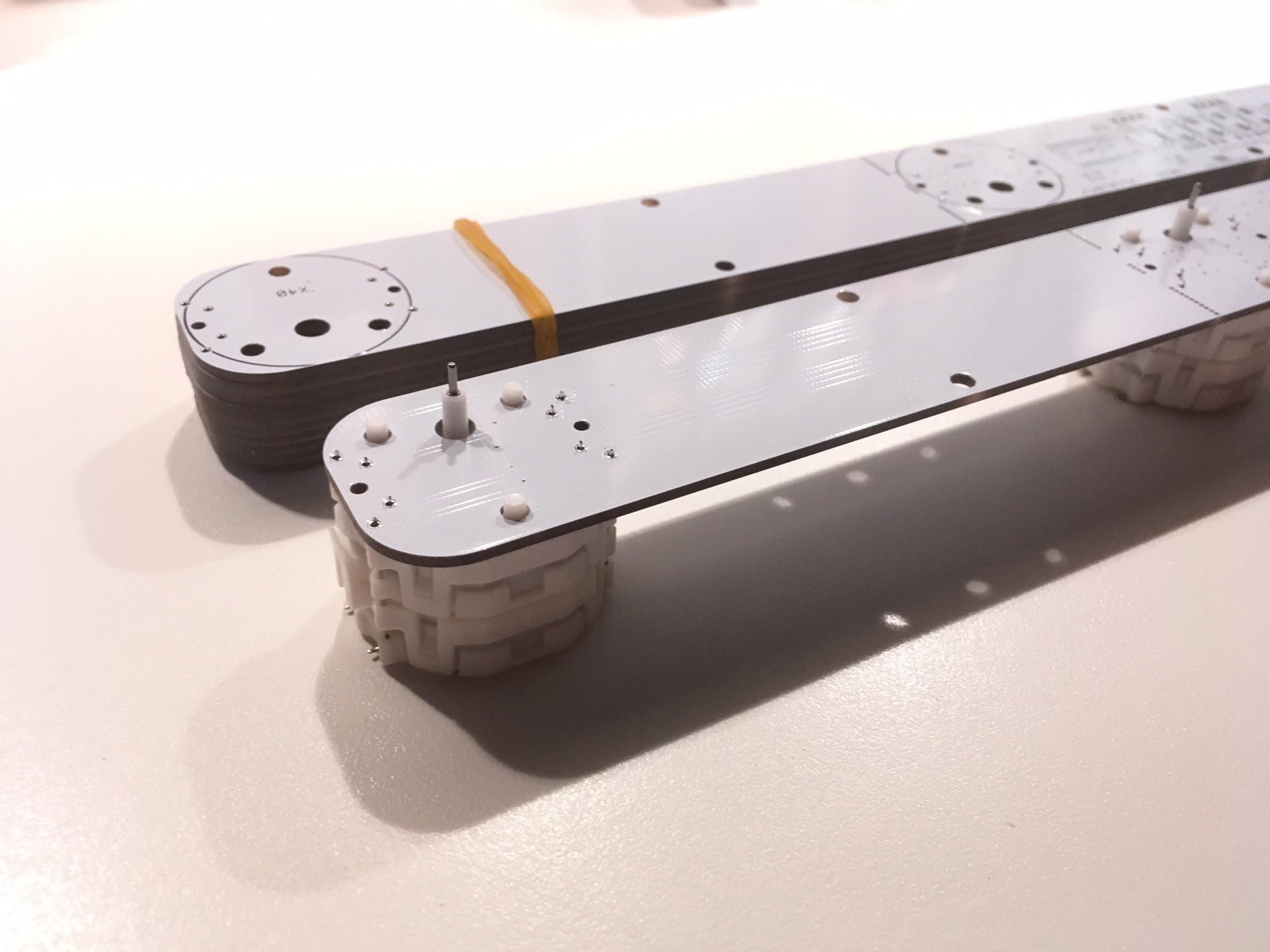
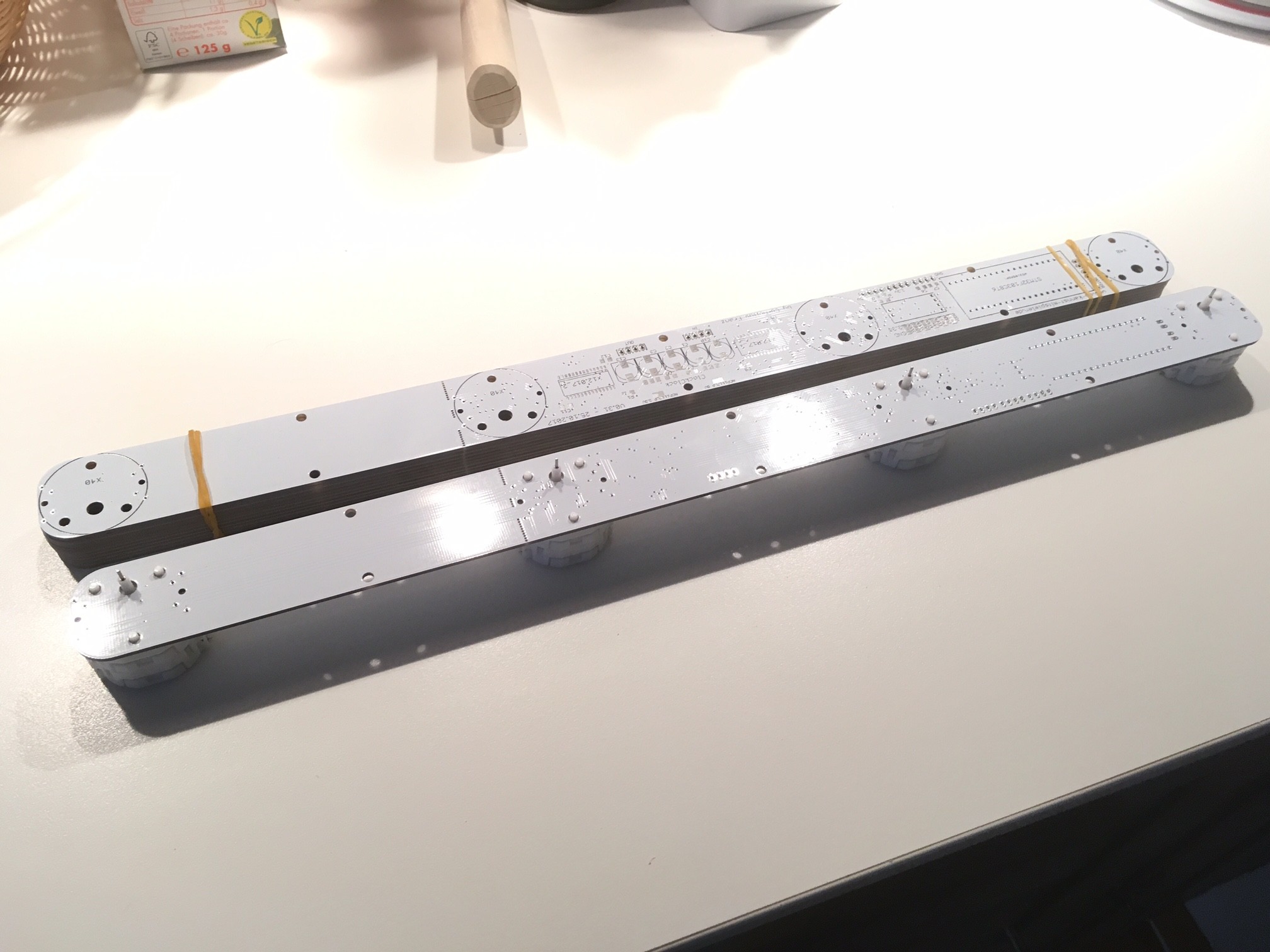
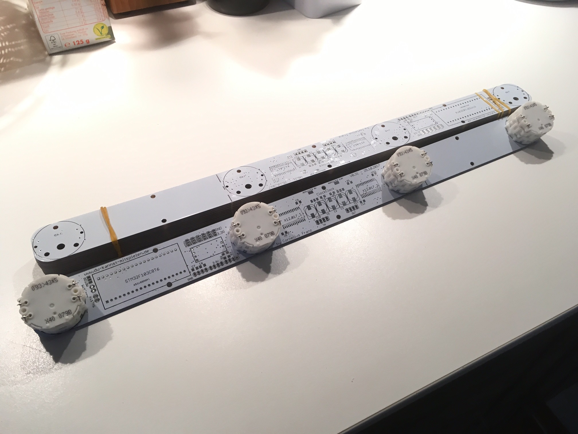
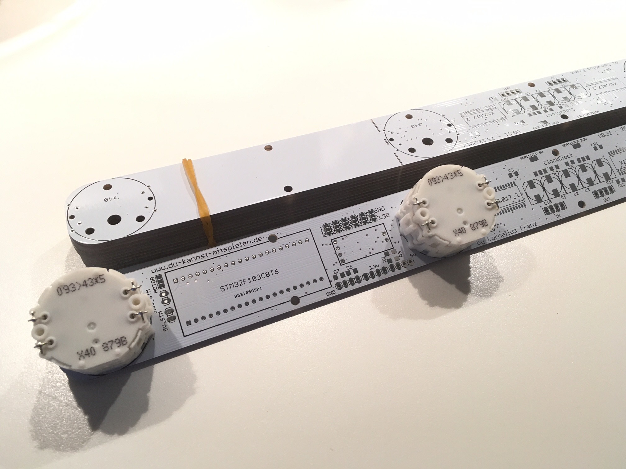
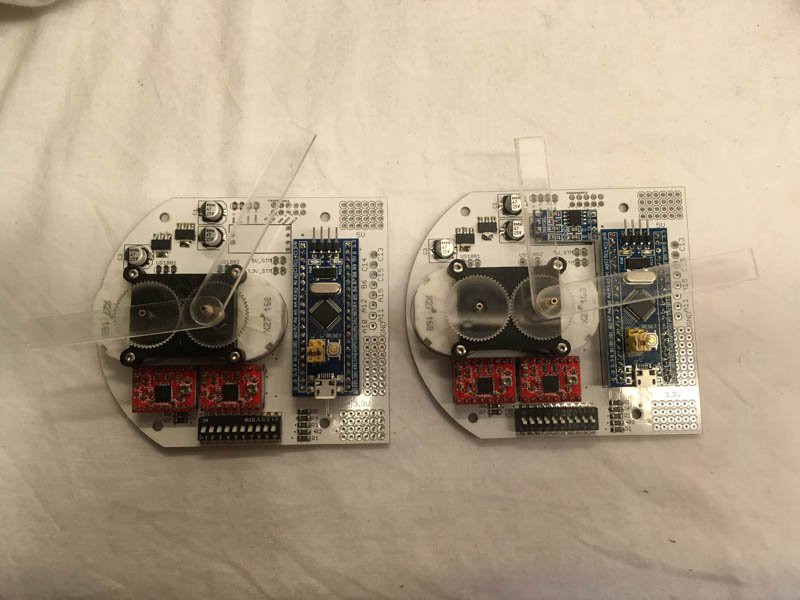
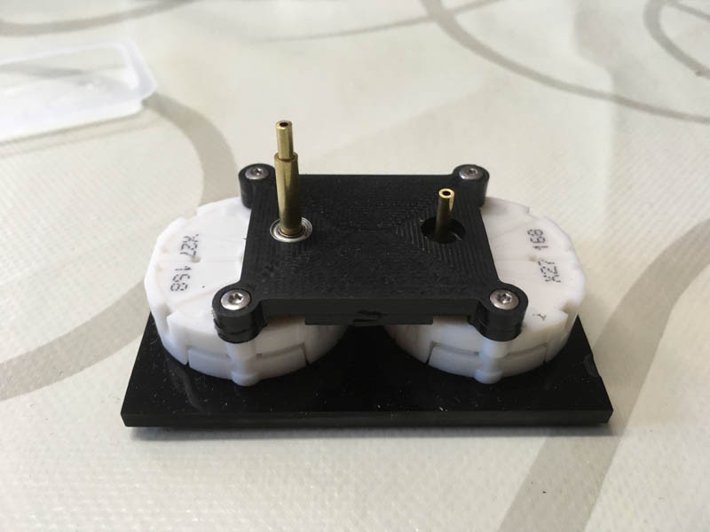
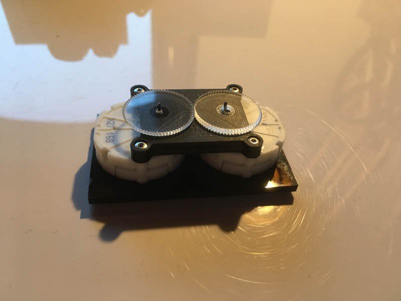
Another attempt of clone the beautiful clock-art-installations of Humans Since 1982
To make the experience fit your profile, pick a username and tell us what interests you.
We found and based on your interests.
JWNB5036.mp4VID29-05 or BKA30D-R5 StepperMPEG-4 Video - 1.33 MB - 04/24/2017 at 18:44 |
|
|
IMG_4415.mp4Sonceboz Slimline 6407 Stepper with calibration.MPEG-4 Video - 8.45 MB - 04/24/2017 at 18:43 |
|
The first prototype with 8 double motors is running :-D
We are still working on the project. The new PCBs are running quite well. So a first prototype might be coming in the next weeks.
We are now fixed with four steppers for each PCB. So each bigger clock should have a horizontal number of individual clocks, which can be divided by four. For the smallest version of 24 clocks it fits perfectly and for any bigger one this shouldn't also be a problem.
Only a short update this time. We are spending the most time on writing the code and are close to the first test of the bus system. The main PCB is also ready. It includes the RTC and an ESP to control everything via wireless connection.
We did a lot of testing different motors, drivers and other things in the last weeks and ended up here. The new concept is running four X40 steppers by two X12.017 drivers by one STM32. The PCB can be cut to just three motors, if necessary. It measures just 40x3cm. The "clocks" will have a diameter of 12cm seperated by 5mm.
The first test PCBs arrived just recently. Everything is soldered for the first run. The gears fit quite well. Now is the time for beginning with the firmware.
The first test parts using the X27 steppers are finished. I'm currently waiting for the first test PCBs. All parts can be directly soldered to the PCB as boards. As soon as the first board is finished, I'll upload some new pictures.
How to reference all the different steppers automatically? We had different ideas but the best solution so far seams to be small magnets and Hall detectors.
We used very small magnets of 1x2mm in size. These were glued directly at or into the gears of the tested steppers.
At the Sonceboz stepper it was pretty easy. Only two little holes have to been drilled and the magnets could be installed.
In the housing of the stepper was enough space for adding the Hall detectors.
The reference detection works pretty well.
Adding all the parts to the VID29-05 was much more difficult even if the housing itself is bigger. Here it runs fine in about 90% of the test, but since we decided to use another stepper there was no further need of improvement.
So where to start at this big project? The first experiments were performed with different steppers to get some experiences, which are suitable for this clock.
We started with the Sonceboz 6407 stepper, which has two concentric shafts and looks very usable for this project. However the price of the motor, even when buying 125 pieces (around 27€ each plus taxes) was way to much.
Another test was performed with the VID29-05 (or the clone BKA30D-R5), which you can get for less than $4 at Alibaba. This motor uses many gears to connect the two individual steppers to one shaft. This leads to an enormous increase of annoying sound while running. Even one stepper is to loud for my personal feeling. So, no chance for the VID29-05.
The next attempt will be with two X27 steppers, connected by two external gears (probably laser cut) to one shaft. The motor costs around $1,50 and the construction is much similar to the Sonceboz 6407.
Create an account to leave a comment. Already have an account? Log In.
Thanks for the information which helps me a lot when I try to make my own 288 version, here is my project https://hackaday.io/project/189332-a-million-times-288-clone
going to share everything there
Hi, I try to do the same click, but I have order bka30d with stop. So now I need to remove 24 stops... The first stop is easy to remove but the second one (behind the metal plate) is really hard to remove... Is there a way to do it easily ?
Thank you !
See images on https://mcuoneclipse.com/2020/06/07/behind-the-canvas-making-of-60-billion-lights/ of the motor, as well on https://mcuoneclipse.com/2019/11/24/world-stepper-clock-with-nxp-lpc845/comment-page-1/: if you have a longer/small really sharp knife, you ca cut the stop below the metal plate too. If not, you really have to remove the gears on top of it.
Thanks for the post. Painting contractors Jacksonville visit us at http://www.painterjacksonvillefl.org/
As far as I can tell they are 3D printed. I'm doing the same for my clocks (see https://mcuoneclipse.com/2019/08/25/diy-stepper-motor-clock-with-nxp-lpc845-brk/). But I'm using PMMA with a laser cutter too: https://mcuoneclipse.com/2020/06/07/behind-the-canvas-making-of-60-billion-lights/
Would it be possible to create a virtual version as a screen saver with the animation files?
I'd love to make / have one!
There are some virtual versions available:
https://malte-wessel.com/a-million-times/
http://cc24.g01l.eu/
Love the work you're doing. I was wondering, what's up with your PCB looking like it only houses one motor per "clock"? How are you rotating both clock hands? In your example video it appears like there's only one x40 behind each section of the PCB...
I'm a big dummy, I didn't realize the x40 is a dual motor. I'm still curious as to how you're connecting the clockhands to the motor and where you got the clockhands though.
Hello CF,
Can you tell me what is the fixed pointer rubber ring in this project? Where to buy? Can you send me a link ?
Thanks.
Great job.
I have thought a lot about a very similar project. The X40 do not have zero detection, how do you know that the X40 is at zero?
Looks like you're making great progress! I've been playing around with the same thing but it seems like I may be better off waiting for your kit. From the looks of the new PCB, did you give up on the idea of hall sensors for registration?
Not at the moment. The connectors for the Hall sensors are still on the PCB. Since the first prototype is running pretty well we now starting with these extra features.
Hey man, love this project, very cool stuff and innovative PCB. I have a question though. For our college senior design class we are working on a project that requires a dual spindle motor and the only place we can find the x40 is Aliexpress and it takes 27 days to get here... would there be anyway we could buy one or two off of you? Would be willing to pay well. Do you by chance know a supplier? Thanks!
I tried this also with X40.879, but I found that the X40.879 does not have both shafts rotating 360 degrees. The limit is something like 315 degree. Do you have the same problem or do you have the X40 with 360 degree rotating shafts? Thank you
I have the "NS (=no stop)" version of the motors. But you can easily cut out the stop. It's on the last gear, a small plastic nob. You just need a sharp knife.
Yes you are right. After cut the small plastic nob it is fully 360 degree motor! But I did not find any version NS motor on internet, can you get me a link or company which produce it?
This is great work! I am more of a SW guy. If you need help on that side just let me know...
I would potentially be interested to re-use your PCBs... Would you be open to share them? Btw, where did you order these PCB from? they look neat ;-)
I'll probably make everything available as a kit. At the moment we are testing the current PCBs with one master and two slaves. It's running pretty well. We may implement a possibility of adding new animations via SD card, but the main goal at the moment is a running prototype of 24 individual clocks at the beginning. Afterwards I'd like to go bigger. There is a huge wall reserved in my kitchen for a 120-faces clock ;-)
ok thx! Trying to progress in parallel then no Pb. Eager to see that picture of your kitchen!
Another question: How did you do your handles and how did you attach them? I have some issues that they stay on the axel of the stepper motor... In my video you see one which is not aligned because he has moved a little bit.
Are you going to share you source code? I'm curious to learn the algorithm to update the display. I think it would make a good Windows screensaver.
Since the code is written by a friend of mine, I can't say if he will share it to the public. But I don't say a definite no at this point. I'll keep you updated here.
I've read that x40 have mechanical stops. Is it easy to remove?
And btw, really nice work!
The stops are not to hard to remove. Same applies to the VID28-05. You have to be careful, but with some patient it's fine.
I struggle with the precision of the VID28-05 stepper. They are loud and shaky... But as they are half the price of the X40 (and you need many of them!) it's still interesting. Did you made a comparison for the noise and stiffness between the VID and X40?
I really liked the Sonceboz steppers. They did not produce any sound or vibration, but the price was much to high. The VID28-05 are very loud and not very precise. There are too much gears inside causing the noise. The X40 are a good compromise, but still noch as cheap as the VID.
Perfect thanks. I have now ordered some X40 to test them.
Become a member to follow this project and never miss any updates
could you please add a little more details on the stepper motors. thanks . Nice work I must say