-
Built the first revision hadware
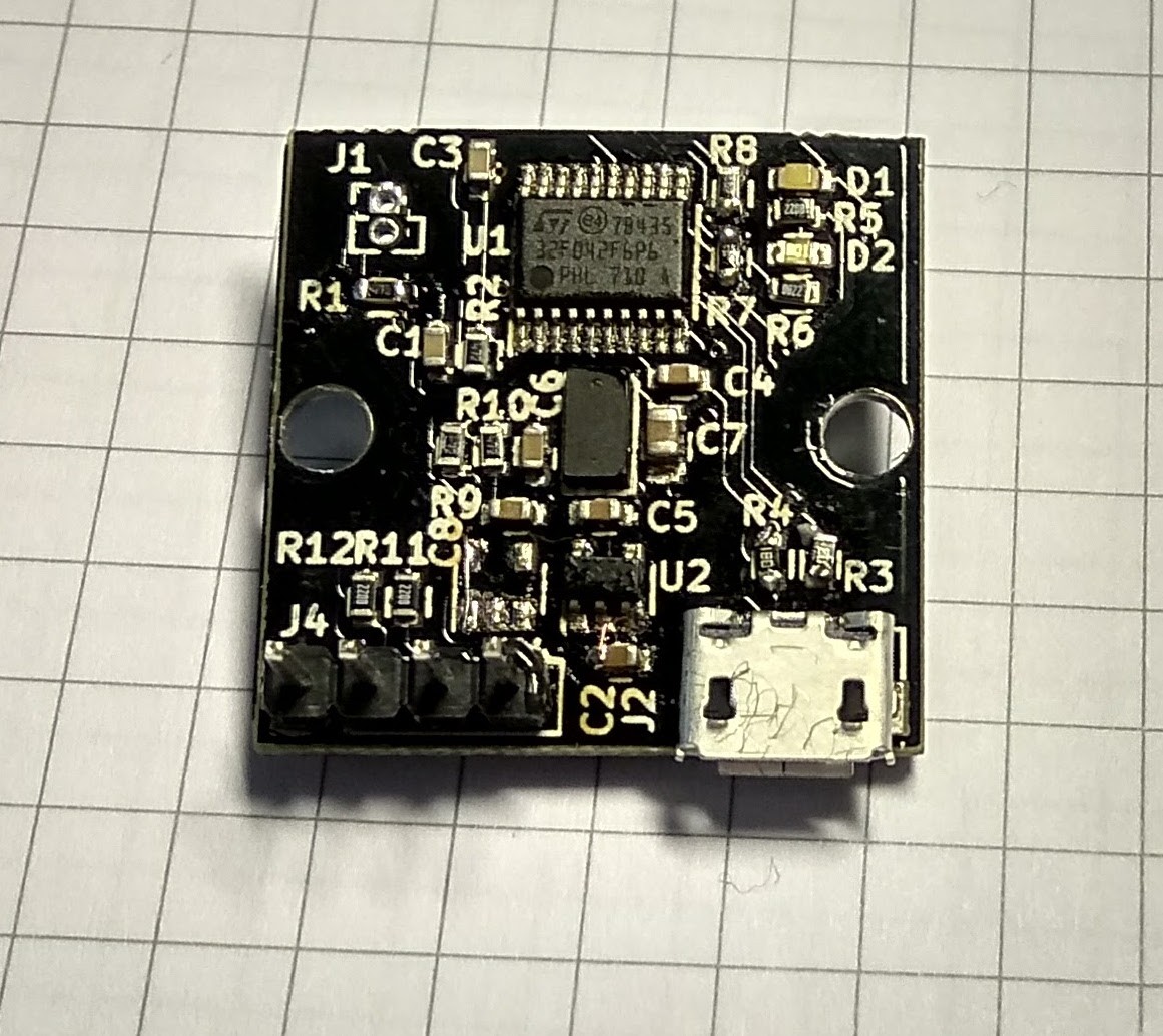
09/09/2017 at 10:43 • 0 commentsThe first revision of the hardware has been built and basic firmware which configures the sensor and outputs sensor readings over USB and UART has been written. The good news- it's functional. The bad news- this won't be the final hardware revision.
![]()
The assembly is not too pretty due to having it reworked multiple times- the initial components were soldered in toaster oven, but I soldered the VL53L0X after that, from some other boards I had been working on.
There are three
fuckupshardware changes:- For some reason, I assumed that voltage regulator's enable input can be left floating. Oops, it has built in pulldown resistor, so I needed to tie the enable input to Vin.
- While PCB was being manufactured, I decided to test VL53L0X sensor operation from 3.3V, as I noticed that many other projects around it don't bother with powering the sensor from 2.8V in 3.3V systems. I could not discern any measurable performance difference (the power dissipation seemed to be a bit higher but that does not matter in this project).
- Selecting DFU mode with BOOT0 pin requires high voltage level, but I had wired ground to jumper's other pin.
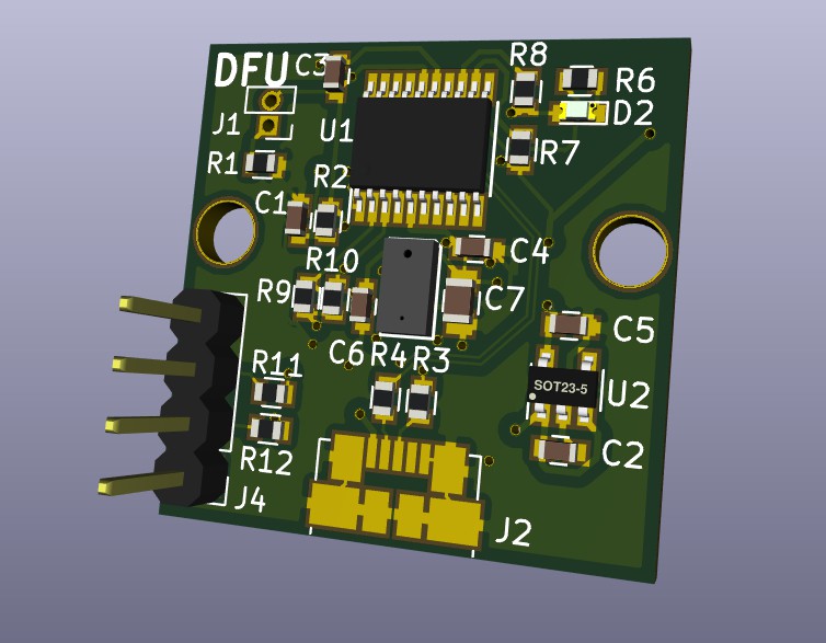
- As I'm pretty sure USB will be the main reason someone would use this board instead of plain breakout board and having some unused space on board due to removing the other regulator, I wanted the USB connector to be centered.
The new hardware revision has already been produced and is now being shipped to me.
![]()
-
Hardware design
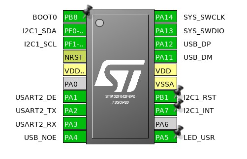
04/24/2017 at 21:52 • 0 commentsThe main system components are VL53L0X distance sensor and STM32F042 micro-controller (MCU). This MCU is one of the smallest ARM Cortex-M0 parts with USB, but still comes in hand-solderable TSSOP-20 package.
Since I have used this sensor and a micro-controller from this family before, I had a good idea on how they both work, so the hardware design was relatively straightforward.
I have found STM32CubeMX pin configuration tool to be very helpful while designing hardware using STM32 parts. It allows to enable all required peripherals and visually see which pins are still free.
![]()
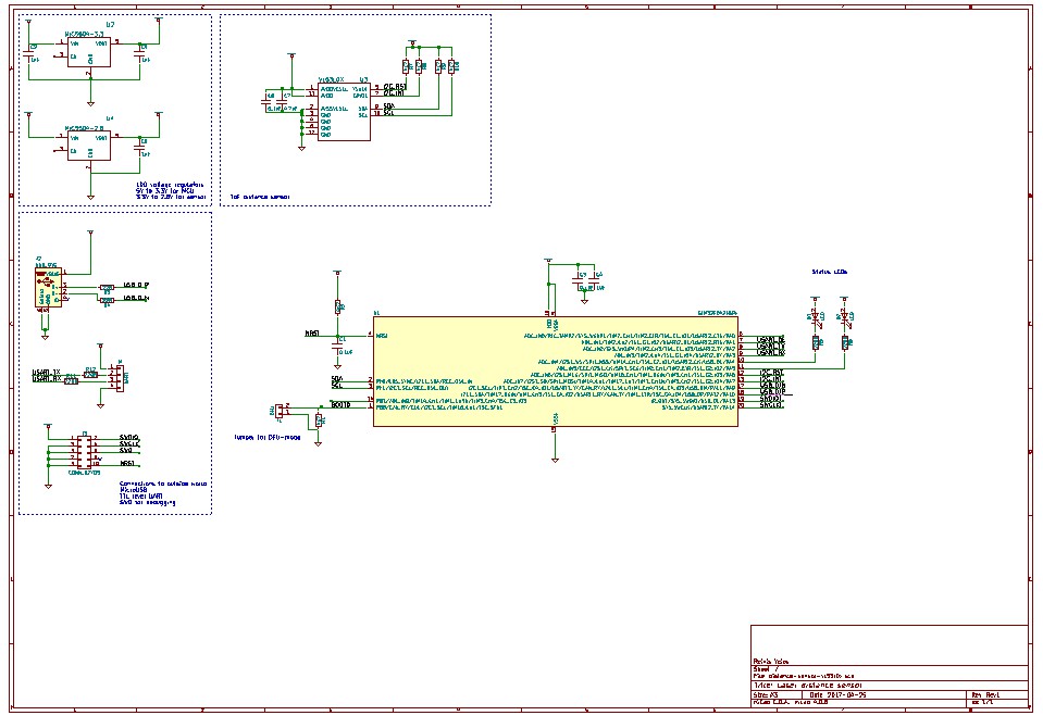
The biggest hurdle is separate power rail for VL53L0X (recommended operating voltage of 2.8V). It would be tempting to power micro-controller from the same 2.8V rail, but STM32F042's USB is guaranteed to function for at least 3.0V power rail.
While it would probably be fine to power both of them from a single 3.0V rail, I decided to power MCU from 3.3V and sensor from 2.8V.
I2C bus between them is pulled to 2.8V. High logic level for MCU for the pins I'm using is 0.5 * VDD + 0.2 ~= 1.8V which is well below 2.8V at which the I2C bus is pulled to.
I chose the ubiquitous MIC5504 series low-dropout linear regulators because they are cheap and have very low dropout voltage.
![Schematics]()
The hardware design for revision 1 is finished and Gerber files are sent for production.
![]()