-
1Flashing the Keymu precompiled Image on the Edison
Download link
The precompiled Keymu image is too big to be uploaded directly on hackaday (which does not support files higher than 50MB) so here if the google drive link:
https://drive.google.com/open?id=0B73FmvhZdYr6MmE2eS02ZEp1Q1U
Flashing the Image
Once you downloaded the zip file, you can start by unzipping it in the folder of your choice. It should contain a folder called "toFlash" containing all images and files required to flash the Edison.
Using Linux
Easy peasy japanesey:
cd toFlash/
sudo apt-get -i install dfu-util libusb-1.0-0-dev
./flashall.sh
It does not always work with virtual machines though, hence the other option:
Using Windows
There is also a dfu-util binary for windows available but I suggest you just download intel_edison_setup_win_v2016.2.007.exe from the Intel page: https://downloadcenter.intel.com/search?keyword=edison
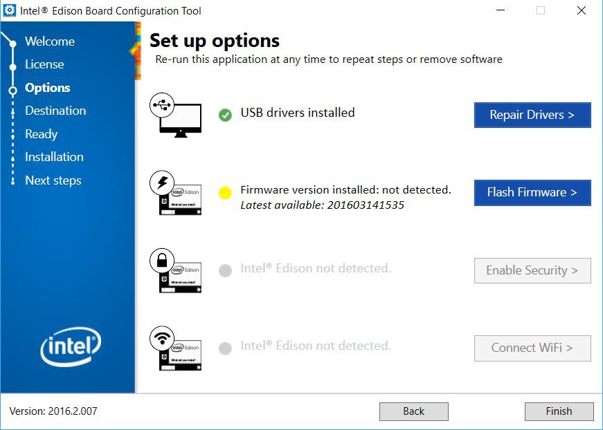
Launch the software and this window will open:
Click on next several times until you arrive at this window:
Here you need to choose the second option: "Flash Firmware".
On to the next window:
Select the second option "Use existing image, located at:". This is here that you need to specify the path to your FlashEdison.json file, in my case: C:\Users\VincentBuso\Desktop\toFlash\FlashEdison.json.
Click on next and you will be prompted to plug in your Edison if you you did not already. Wait for about 5 to 10 minutes and Voilà, Your Edison is freshly flashed with the Keymu precompiled image.
Let's try to turn it on...
Start playing
Assuming you followed log 3 until the end and you have a fully soldiered PCB at the ready (battery and all), you can now plug in the newly flashed Edison, turn on the switch and pray...
Now the blue LED should already turn on, but the screen will need around 20 seconds before starting... just be patient. 20 seconds can seem very long when you are waiting in full anticipation but don't start biting your fingernails yet because - hey look - it works !
Congratulations ! You now have a fully working prototype of Keymu, now let's dress it up.
-
23D printing
The STL files are available on Thingiverse or directly from the project files.
These STL files are for 3D printing or visualization, if you feel like modifying the 3D design and missed Log#4, don't worry: all the Solidworks source files are available here.
No 3D printer, no problem
I am aware not everyone owns a 3D printer, in fact neither did I when I built the first prototype. Platforms like 3DHubs for finding people around you with 3D printers exist and work really well. The casing you see in the youtube video showing Keymu in action has actually been printed by a previously unknown neighboor of mine that I met on 3Dhubs. Another alternative is to find an hackerspace next to your place where 3D printers are available.
Of course if you plan on reworking the design, then I would suggest having a 3D printer at hand: unless you have extraterrestrial skills you won't have everything right the first time, or the second, or the third... So it's best if you can launch prints incorporating your new little modifications whenever you want. Another great advantage of owning a 3D printer is having complete control over your Slicer software/settings. This makes a huge difference
Slicer software
The slicer software is basically what will translate the STL file into gcode: your printer's language. Nowadays slicer softwares are much more than that and configuring a print right can make all the difference.
I warmly recommend using Simplify3D as your Slicer software, it gives you a lot more controls over your prints, and most importantly over your support materials.
General stuff
Keymu was designed to be built without screws, only snap fit parts, this implies several things:
- Keymu is small, and details matter at this size, I recommend printing at 100um or less if your printer can do it, and I also recommend having a heated bed.
- When designing your 3D files, be sure the intricate parts have a tolerance of at least 200um.
- When choosing your material for printing, be sure to get one designed for small details. The standard PLA from rigid.ink worked very well for me, and I refer you to filaween to find your best pick.
Another thing that made all the difference during the prints was adding a skirt with 0mm offset from the parts, and variable length depending on their function. For exemple they are great for parts that have fileted edges right from the first layer, instead of adding support material to support the little overhang part at the begining of the filet. They are also great when printing the buttons, which are very small parts, all at once: it creates an interconnecting layer between them, so they will be less likely to move or fall out during the print.
Support material
Support Material is necessary for many of Keymu's parts, this is when Simplify 3D stands out from the other slicers: automatically generated supports are almost never perfect, and Simplify 3D offers you the possiblility to add or remove supports manually.
For Keymu's support materials I would recommend default settings appart from these values:
- 4mm support pilar resolution (easier to remove while still close enough for overhangs)
- 2 or 3 support base layers
- No dense support layer
- Two perpendicual support infill angles ([-45°, 45°] or [0, 90°])
One STL at a time
This is the part where you can find the Slicer configurations that worked best for me. I do not claim providing the best one, it depends on many things, starting by your 3D printer itself.
The parts that don't need support
Assuming your printer's resolution is around 100um or less, the following parts can be printed without issues since they do not require any support:
- Keymu_A.stl
- Keymu_B.stl
- Keymu_LR.stl (x2)
- Keymu_OnOff.stl
- Keymu_Select.stl
- Keymu_Start.stl
- Keymu_X.stl
- Keymu_Y.stl
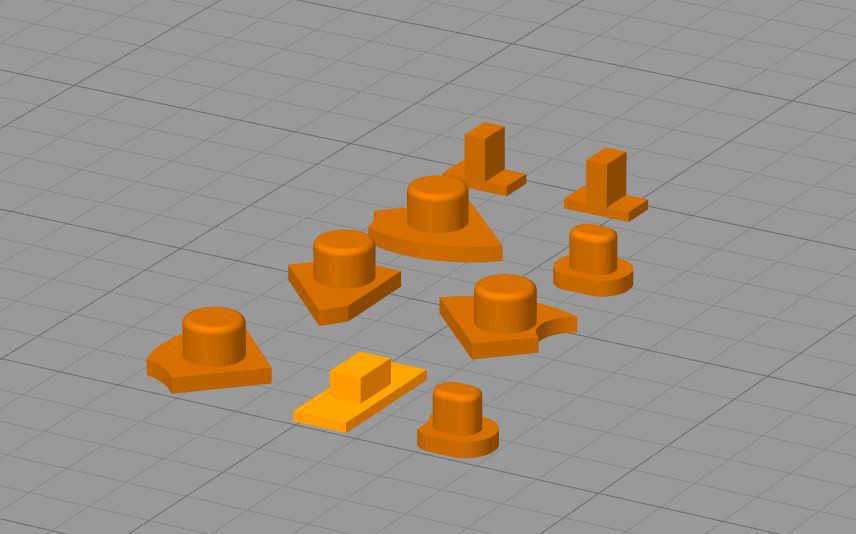
Just print them on the following sides:
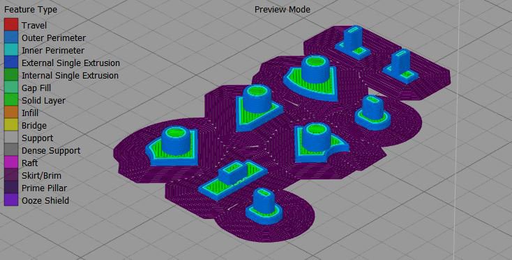
And don't forget to add the skirts (here with 15 outlines so that the part interconnect)
Also for this print you need to turn on retraction for the nozzle otherwise you'll have plenty of unwanted spider webs between your parts.
The lighter orange part is the on/off button, it is hollow inside so there is an overhang but it is so small that it shouldn't pose any problem if you have a good quality filament and decent ventilation on your nozzle.
The arrows
Now we are getting started with the parts that do require support material, starting by the arrows. Because of the spherical part under them, the arrows need to be printed from top to bottom.
The skirt is not necessary here, I'm just a big fan of them, they're never too much.
The screen case
The support material should only be necessary for the parts that enter the hinge on both extremities, since here the skirt helps supporting the overhang at the start of the fileted edged.
The main part
This one is the hardest to print. I found that printing it from the bottom up rendered the best. Because of the snap/fit connection with the bottom part, there are overhangs on all sides, so be sure the automatic support generation does not forget them.
For this part, I also suggest adding a raft (not present in the images below), it will make sure there is no warping on the bottom corners.
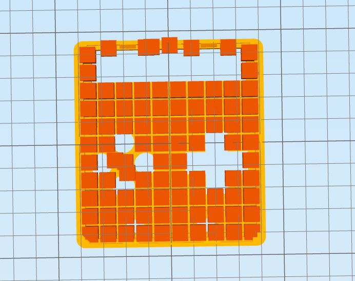
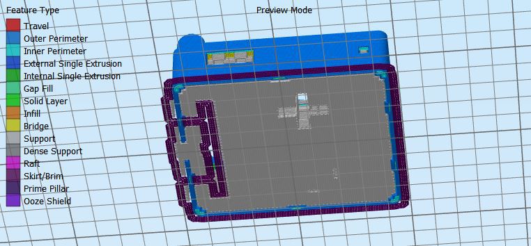
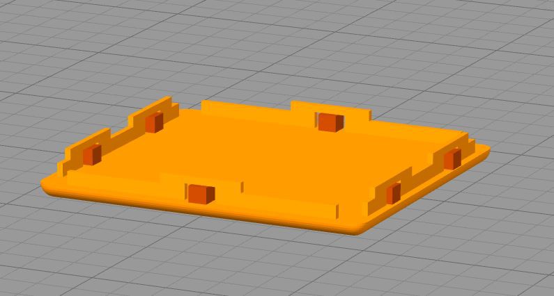
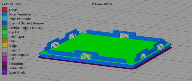
The bottom part
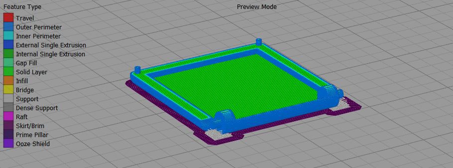
This last part is faily easy to print, just make sure there is support material under the overhangs for the snap fit parts and - as always - make sure you add a good old skirt.
Keymu - open source keychain-sized gaming console
A fully functional, completely open-source, and totally nerdy keychain-sized multi-platform emulation console to build yourself.
 c.Invent



Discussions
Become a Hackaday.io Member
Create an account to leave a comment. Already have an account? Log In.