Close
0%
0%

Arduino MEGA 2560 32Kb RAM shield

A simple Arduino mega SRAM expansion.

Similar projects worth following
A simplest possible SRAM expansion for Arduino MEGA 2560 compatible boards. It adds 32Kb to internal 8Kb of Atmega2560 and allows to run much more complex programs on the board.Terminal-BASIC interpreter from https://sourceforge.net/projects/terminal-basic/ is one of the applications, ready to use this item.

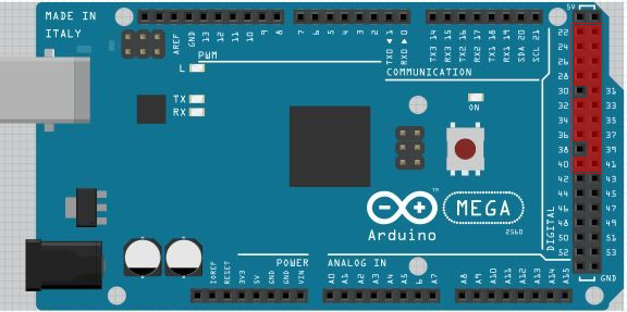
Used arduino pins scheme.
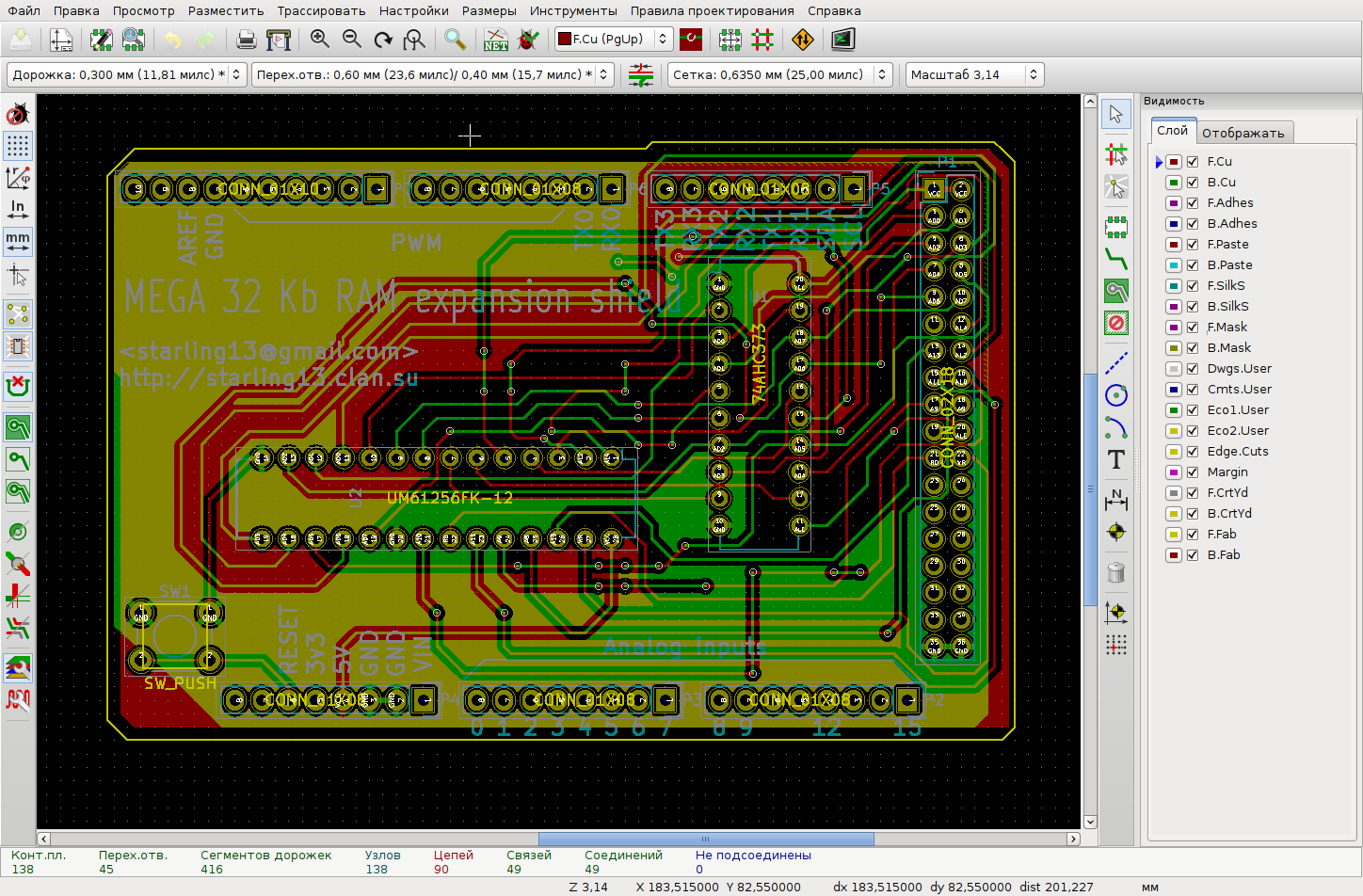
KiCad sceenshot with current result.
Arduino IDE sketch for testing the shield on different wait states

/*
 * This is free and unencumbered software released into the public domain.
 * 
 * Anyone is free to copy, modify, publish, use, compile, sell, or
 * distribute this software, either in source code form or as a compiled
 * binary, for any purpose, commercial or non-commercial, and by any
 * means.
 * 
 * In jurisdictions that recognize copyright laws, the author or authors
 * of this software dedicate any and all copyright interest in the
 * software to the public domain. We make this dedication for the benefit
 * of the public at large and to the detriment of our heirs and
 * successors. We intend this dedication to be an overt act of
 * relinquishment in perpetuity of all present and future rights to this
 * software under copyright law.
 * 
 * THE SOFTWARE IS PROVIDED "AS IS", WITHOUT WARRANTY OF ANY KIND,
 * EXPRESS OR IMPLIED, INCLUDING BUT NOT LIMITED TO THE WARRANTIES OF
 * MERCHANTABILITY, FITNESS FOR A PARTICULAR PURPOSE AND NONINFRINGEMENT.
 * IN NO EVENT SHALL THE AUTHORS BE LIABLE FOR ANY CLAIM, DAMAGES OR
 * OTHER LIABILITY, WHETHER IN AN ACTION OF CONTRACT, TORT OR OTHERWISE,
 * ARISING FROM, OUT OF OR IN CONNECTION WITH THE SOFTWARE OR THE USE OR
 * OTHER DEALINGS IN THE SOFTWARE.
 * 
 * For more information, please refer to 
 */

static void testOk() {
  digitalWrite(LED_BUILTIN, HIGH);
  delay(500);
  digitalWrite(LED_BUILTIN, LOW);
  delay(500);
}

static void testFail() {
  for (uint8_t i=0; i<3; ++i) {
    digitalWrite(LED_BUILTIN, HIGH);
    delay(50);
    digitalWrite(LED_BUILTIN, LOW);
    delay(50);
  }
}

void log(const char *str) {
  div_t d = div(millis(), 1000);
  Serial.print(d.quot), Serial.write('.'), Serial.print(d.rem);
  Serial.print(" >>> ");
  Serial.println(str);
}

static volatile uint8_t *extmem = reinterpret_cast<volatile uint8_t*>(0x8000);

bool test() {
  for (uint16_t i = 0; i<32768; ++i) {
    extmem[i] = (i+1) & 0xFF;
  }
  for (uint16_t i = 0; i<32768; ++i) {
    if (extmem[i] != ((i+1) & 0xFF))
      return false;
  }
  return true;
}

void setup() {
  long startTime, stopTime;
  bool res;

  auto doTest = [&]() {
    delay(1000);
    startTime = millis();
    res = test();
    stopTime = millis();
    if (res) {
      log("PASSED, time (ms):"), Serial.write('\t');
      Serial.println(stopTime-startTime);
      testOk();
    } else {
      log("FAILED");
      testFail();
    }
  };

  Serial.begin(9600);
  pinMode(LED_BUILTIN, OUTPUT);
  log("Enabling external memory interface");
  bitSet(XMCRA, SRE);  // enable externalmemory
  bitSet(XMCRB, XMM0); // release unused pin PC7
  
  log("1. Wait cycles: 2 + 1");
  bitSet(XMCRA, SRW11);
  bitSet(XMCRA, SRW10);
  doTest();

  log("2. Wait cycles: 2");
  bitSet(XMCRA, SRW11);
  bitClear(XMCRA, SRW10);
  doTest();

  log("3. Wait cycles: 1");
  bitClear(XMCRA, SRW11);
  bitSet(XMCRA, SRW10);
  doTest();

  log("4. Wait cycles: 0");
  bitClear(XMCRA, SRW11);
  bitClear(XMCRA, SRW10);
  doTest();

  log("Finished");
}

void loop() {
  // nothing to do
}

Earlly breadboard prototype testing

BASIC computer, based on the prototype board soldered version:


avrextmem_r0.1.tar.gz

Hardware and software sources

x-tar-gz - 46.39 kB - 05/03/2017 at 15:45

Download

pcb2.zip

PCB production files

x-zip-compressed - 45.94 kB - 04/28/2017 at 15:18

Download

  • 1 × UM61256FK-15 Memory ICs / Static RAM (SRAM) or another, pin compatible
  • 1 × SN74AHC373 Octal transparent D-latch with 3-state outputs
  • 1 × Tact switch For reset, optional
  • 1 × A set of arduino mega shield pinheads
  • 1 × PCB or prototyping board

  • New PCB's

    Andrey Skvortsov02/19/2020 at 18:48 0 comments

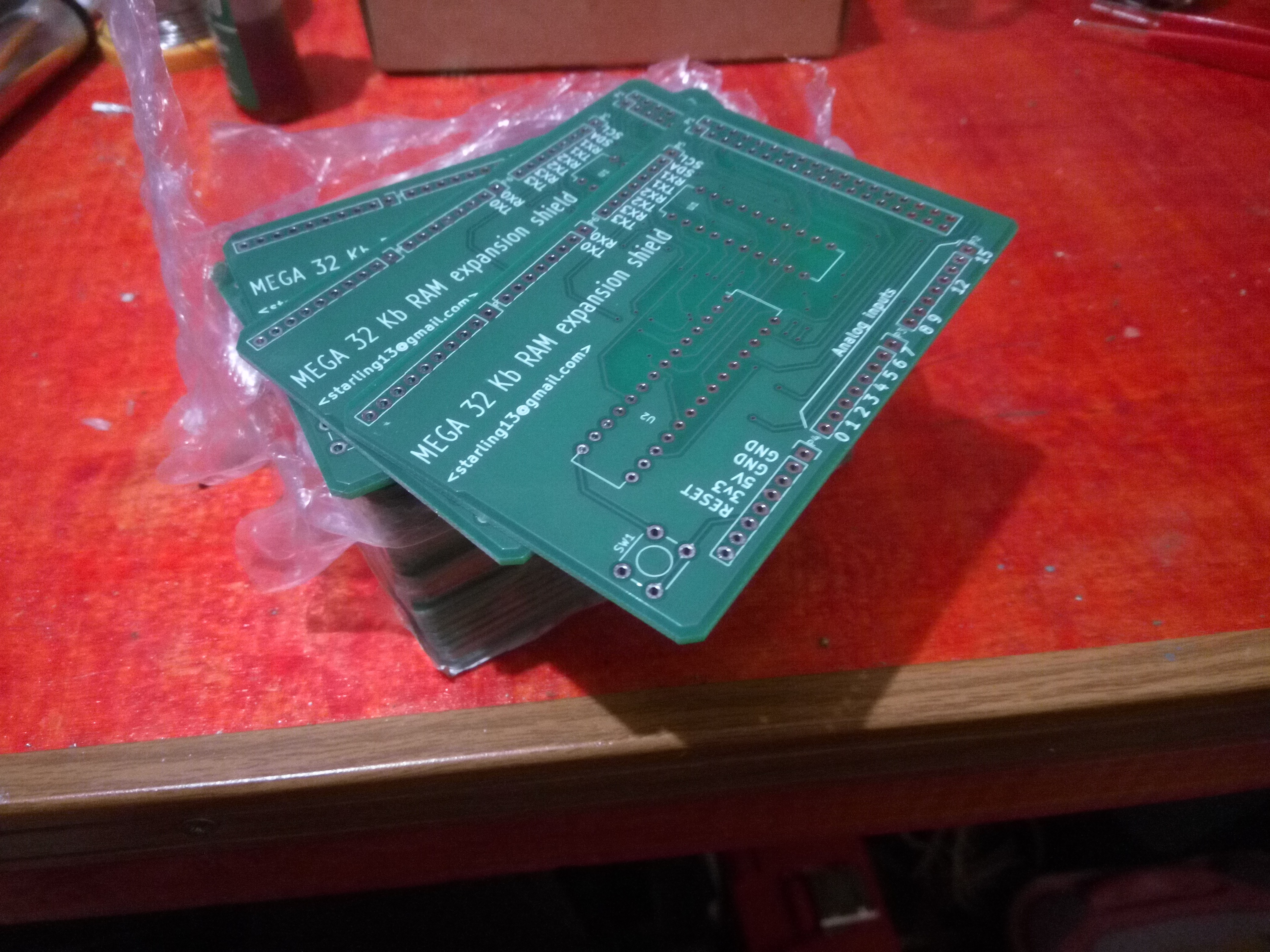
    New set of PCB's have just arrived, waiting to become gifts to friends and items on tindie.

  • Using external memory as heap storage

    Andrey Skvortsov05/05/2019 at 15:37 0 comments

    According to avr-libc documentation the most flexible way to manage the  different memories of AVR mcu is linker script. But if Arduino IDE is being used, this way is not obvious to implement, because there is no Makefile.

    Therefore, there are two simplest ways to use external memory on Arduino MEGA.

    1. The low-level way of readings and writings, based on volatile pointer to external memory area. Test program from this page gives an example.

    External memory occupies area of 0x8000 to 0xFFFF in Atmega2560 address space.

    Suppose we need an array of 8192 float values to write values from some probes. Then simply declare:

    volatile float* dataBuffer = reinterpret_cast<volatile float*>(0x8000);

     Then it's possible to use dataBuffer as pointer to array of 8192 float numbers (8192 * 4 = 32768, the size of external memory):

    ...
    dataBuffer[i] = analogRead(N);
    ...
    Serial.println(dataBuffer[j]);
    ... 
    

    2. The second way is to place heap memory area to external memory:

    void setup()
    {
      Serial.begin(115200);
      
      XMCRA |= 1ul<<7; // Switch ext mem iface on
      XMCRB = 0;
      __malloc_heap_start = 0x8000;
      __malloc_heap_end = 0xFFFF;
    
      uint32_t* dataBuffer = new uint32_t[1024];
      Serial.print("Dynamic buffer of 4096 bytes created, address: ");
      Serial.println((uintptr_t)dataBuffer, HEX);
    
      for (size_t i=0; i<1024; ++i) {
        dataBuffer[i] = i*16;
      }
    
      for (size_t i=0; i<1024; i+=4) {
        Serial.println();
        Serial.print(i, DEC);
        Serial.print('\t');
        Serial.print(dataBuffer[i], DEC);
        Serial.print('\t');
        Serial.print(dataBuffer[i+1], DEC);
        Serial.print('\t');
        Serial.print(dataBuffer[i+2], DEC);
        Serial.print('\t');
        Serial.print(dataBuffer[i+3], DEC);
      }
      
      delete [] dataBuffer;
    }
    
    void loop()
    {
      delay(1000);
    }

    At the begining we set 2 internal avr-libc variables to the external memory boundaries:

     __malloc_heap_start = 0x8000;
     __malloc_heap_end = 0xFFFF;

    After that simple variables and objects, declared at the module level or inside functions will be placed at the 8192 bytes of AVR internal RAM, but all dynamic variables and objects will be placed at external memory.

    You can declare multiple arrays or simple variables:

    float tempBuffer = new float[512];
    assert(tempBuffer != nullptr);
    ...
    tempBuffer[i] = readData(source);
    ...
    delete [] tempBuffer;
    ...
    

    It's possible to use external memory for example with some libraries:

    https://bitbucket.org/starling13/libps2

    include "ps2_keyboardstream.hpp"
    
    #define DATA_PIN 5
    #define CLK_PIN 2
    
    static PS2::Keyboard* kbd;
    static PS2::KeyboardStream* kstream;
    
    void
    setup()
    {
      XMCRA <<= 1<<7;
      XMCRB = 0;
      __malloc_heap_start = 0x8000;
      __malloc_heap_end = 0xFFFF;
    
      kbd = new PS2::Keyboard;
      kstream = new PS2::KeyboardStream(*kbd);
    
      Serial.begin(115200);
      kbd->begin(DATA_PIN, CLK_PIN);
      
    }
    
    void
    loop()
    {
      while (kstream->available() > 0)
        Serial.write(kstream->read());
    }

View all 2 project logs

Enjoy this project?

Share

Discussions

Randy Stadham wrote 03/12/2021 at 03:25 point

Hi any plans to make more boards to sell?  If I knew how to order PC boards  I could do it myself but I have never done that before.

  Are you sure? yes | no

Andrey Skvortsov wrote 03/12/2021 at 08:37 point

There are still 4 boards remain. These boards are assembled, but don't pass test due to broken chips. After change of the ICs I will place them on tindie.

pcb2.zip from files section contains ready-to-send-to-manufacturer production files.

I ordered first 10 boards from chinese manufacturer from AliExpress, then ordered 30 boards from russian РЕЗОНИТ factory https://www.rezonit.ru/


I have no plans to make another boards. Instead I think of another variant, still with through holes components, but with 64k SRAM, buffering capacitors at ICs and a hole to ICSP connector of MEGA board.

  Are you sure? yes | no

Peabody1929 wrote 05/25/2019 at 23:13 point

On the part pad footprints, it would be good to indicate Pin 1 by making the pad square or placing a Dot on the silk screen.

  Are you sure? yes | no

Andrey Skvortsov wrote 05/27/2019 at 10:08 point

Yes, It's my fault. I relied on KiCad but it has default DIP components w/o markers and  such markers should be placed manually.

  Are you sure? yes | no

Ken Yap wrote 05/27/2019 at 10:34 point

Hmm what version Kicad are you using? My footprints on the F silkscreen have the U shaped notch at the 1 end and also the 1 copper pad is square.

  Are you sure? yes | no

tigerorange1 wrote 09/27/2018 at 16:50 point

Would it be possible to cut a slot in the shield so the debugger cable can reach  down to the ICSP pins on the Mega 2560? I use Atmel ICE debugger and it needs to connect there to debug.

https://www.arduino.cc/en/Reference/SPI

  Are you sure? yes | no

Andrey Skvortsov wrote 01/03/2019 at 18:34 point

Sorry, this design has no passthrough ICSP socket. But I think all necessary pins are available on signal sockets of digital and analog IO.

  Are you sure? yes | no

Peter Sieg wrote 07/09/2018 at 11:38 point

1st. Many thanks for this pcb 32k memory expansion!

The test program supplied at above link is using the following test:

bool test() {  

for (uint16_t i = 0; i<32768; ++i) {    extmem = i & 0xFF;
  }
  for (uint16_t i = 0; i<32768; ++i) {
    if (extmem != (i & 0xFF))
      return false;
  }
  return true;
}
The problem here is and was in my case, that the data value is the SAME as the lower 8-bit of the address!
Thats a bad idea with a multiplexed data/address bus.

Now, I had a bad 74LS373 latch - and guess what - I read back the lower 8 address bits = same as extected data value => test program said all is ok!

That took my hours to find that out! Before that I measured all pcb traces - all ok.

Than I modified the test program:
bool test() {
  for (uint16_t i = 0; i<32768; ++i) {
    extmem = (i+1) & 0xFF;
  }
  for (uint16_t i = 0; i<32768; ++i) {
    if (extmem != ((i+1) & 0xFF))
      return false;
  }
  return true;
}
Now the expected value is address+1 - and yes - now the test program reported that it failed!

Second 74LS373 was also bad - but third one was fine and now it runs as expected.

thx, Peter

PS: Now my apple 1 emulator also has 32k memory ;-)

  Are you sure? yes | no

Andrey Skvortsov wrote 01/03/2019 at 18:43 point

Thank you. I'v noticed this problem too while testing my boards and now I changed the test code with your corrections. I glad if my humble efforts were useful.

  Are you sure? yes | no

Dylan Brophy wrote 05/12/2017 at 23:04 point

Why not have the arduino page the memory so that it can get EVEN MORE than 32k?  like, 512k?  

  Are you sure? yes | no

Andrey Skvortsov wrote 05/14/2017 at 17:40 point

There is an outstanding design, based on the AS7C4096A 512 Kb SRAM IC.

http://andybrown.me.uk/2011/08/28/512kb-sram-expansion-for-the-arduino-mega-design/

The shield based on that design was sold for near 50$ as long as good MEGA clones cost less then 10$. I thought of something very simple and cheap (10-11$ for item). And 32K is the biggest SRAM IC, that could been used without losses, due to internal RAM and registers address space of 8 Kb and without bank switching. In any case, 40 Kb continuous address space is much bigger then internal 8 Kb.

  Are you sure? yes | no

Dylan Brophy wrote 05/14/2017 at 20:08 point

Yep!  that's kinda what I was thinking of.  Another idea I had was to use not only RAM, but SRAM pin-compatible EEPROM chips, like the AT28C256.  That way SD cards wouldn't need to hold the OS.  And those EEPROMs are easier to program for me than writing to an SD card; I have no SD card slot in my desktop.

  Are you sure? yes | no

Andrey Skvortsov wrote 05/15/2017 at 09:06 point

Interesting, but as I can see, AT28C256 offers 150 nS access. It's worth to count exactly, if it could been used at the longest external memory delays, ATmega can provide, but seems too slow to simply place it on the main data bus.

Another option is to use relatively fast NVRAM chips.

  Are you sure? yes | no

Dylan Brophy wrote 05/15/2017 at 13:52 point

yes.  And I forget how fast FLASH is, but that has memory protection... 

  Are you sure? yes | no

Dylan Brophy wrote 05/05/2017 at 13:11 point

Wait, let me get this strait.  The arduino MEGA has GPIO for parallel memory access???

  Are you sure? yes | no

Andrey Skvortsov wrote 05/05/2017 at 13:21 point

Yes, at least Atmega1280, Atmega2560, Atmega128 and some legacy mcus has an external memory interface with 8 bit data bus and 16 bit address, but the address bus requires a buffer because most and least signed address bytes are placed on the bus sequentionally to save pins.

  Are you sure? yes | no

Dylan Brophy wrote 05/05/2017 at 17:58 point

You should consider selling it on Tindie.  Send me a message and I'd be very interested.  A parallel RAM shield would be much, MUCH faster than SPI or any serial.  And I use a mega for my #Arduino Desktop

  Are you sure? yes | no

RX HMP wrote 05/05/2017 at 09:47 point

work with uno?

  Are you sure? yes | no

Andrey Skvortsov wrote 05/05/2017 at 13:18 point

No, it doesn't. Atmega328 and Atmega168 MCUs haven't an external memory interface, which will took away 19 I/O pins if exists.

  Are you sure? yes | no

Yann Guidon / YGDES wrote 05/02/2017 at 13:39 point

Is the access time critical ? You use 15ns type memory that draws quite a significant current. Other slower SRAM chips (in the 70ns range) draw much less, did you consider this ?

  Are you sure? yes | no

Andrey Skvortsov wrote 05/02/2017 at 14:20 point

The atmega external RAM interface has different settings of wait states during read/write operations. And, I think, the extarnal RAM access time must be less then 30 ns to use no wait state operations on 16MHz clock (which in any case are 30% slower then operations with an internal SRAM).

But if the MCU clock is slower or RAM access time is not a bottleneck, I think it's possible to use 70 ns RAM with 2 clocks wait state settings.

  Are you sure? yes | no

Yann Guidon / YGDES wrote 05/02/2017 at 14:49 point

Speed versus power consumption : the old dilemma...

  Are you sure? yes | no

Capt. Flatus O'Flaherty ☠ wrote 05/02/2017 at 09:47 point

Thanks - about 18 pins it seems.

  Are you sure? yes | no

Capt. Flatus O'Flaherty ☠ wrote 05/02/2017 at 08:33 point

Looks very useful. How many I/O pins are used by the RAM?

  Are you sure? yes | no

Andrey Skvortsov wrote 05/02/2017 at 09:35 point

I should place additional schematics to clear available pin set.
It uses the Atmega 2560 external RAM interface pins:
- Port A (AD0-AD7) - digital pins 22-29 of MEGA;
- Port C (A8-A15) - digital pins 30-37;
- Port G (WR, ALE, RD) - digital pins 39,40,41;

  Are you sure? yes | no

Andrey Skvortsov wrote 05/02/2017 at 10:07 point

Actually A15 is not used, but in external memory use mode it can't be used as GPIO pin.

  Are you sure? yes | no

Similar Projects

Does this project spark your interest?

Become a member to follow this project and never miss any updates