-
Some Fixes
09/24/2017 at 10:07 • 0 commentsI wrote the library for the PewPew 3.0 version, and also did some more testing of the hardware, which uncovered a number of mistakes.
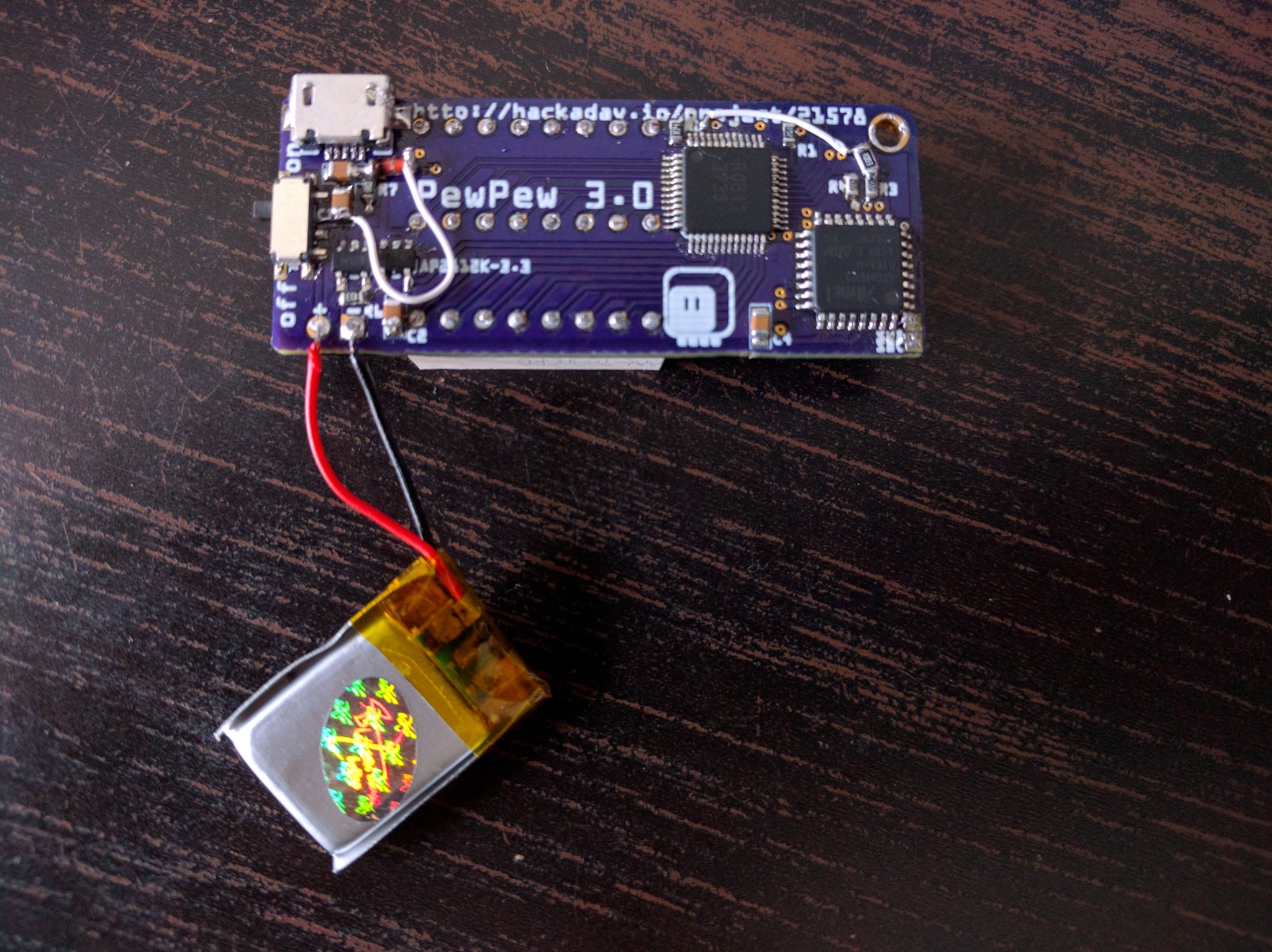
First of all, I forgot a pull-up resistor for the SDB pin of the IS31FL3733 that acts as enable pin — which means the display would switch off randomly. I added that with a piece of wrapping wire.
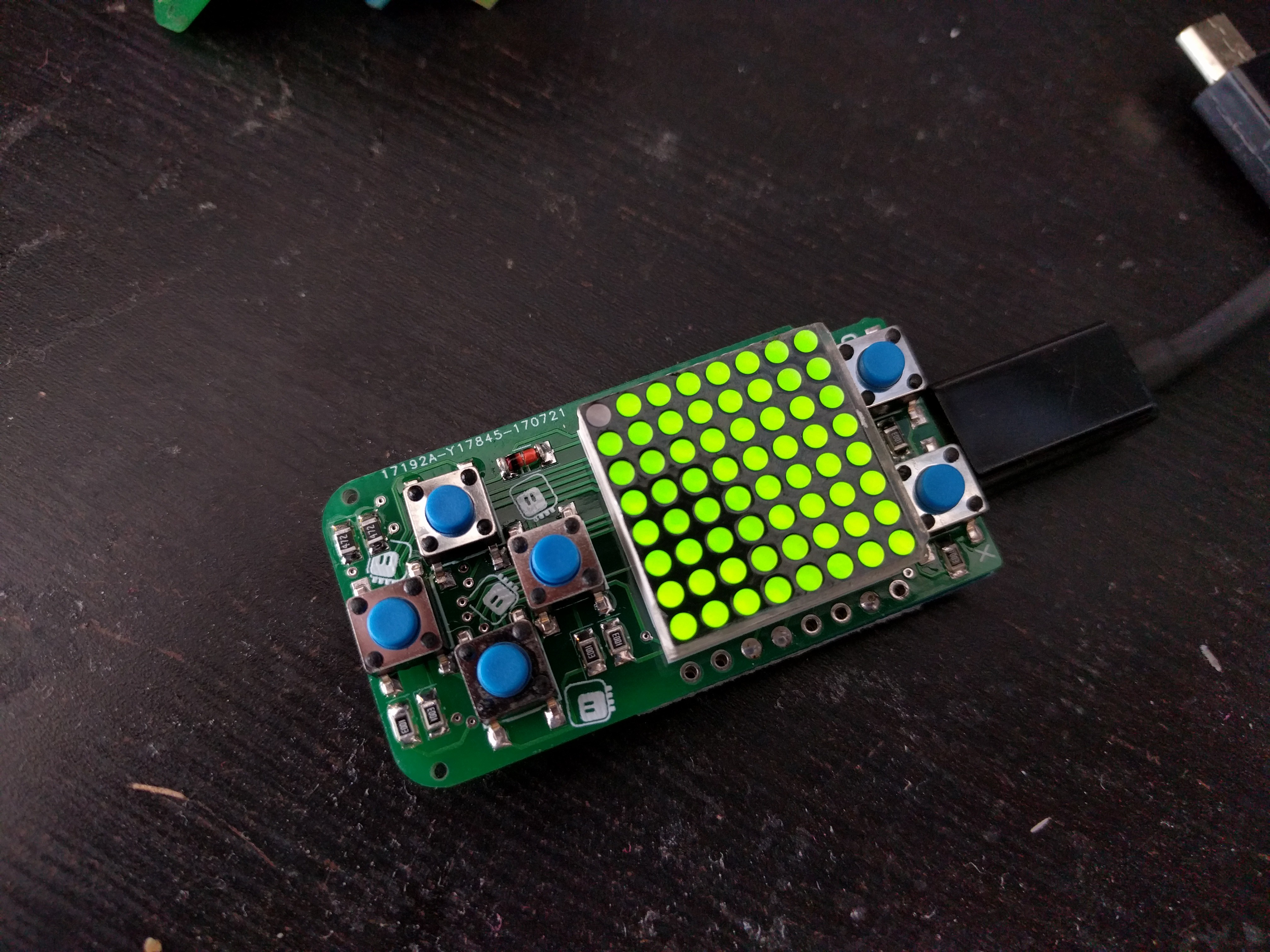
Second, the battery circuit didn't work, and it took me a while to realize that I forgot to connect it to the rest of the power of the device. That requires a Shottky diode, so that we don't send power up the USB cable when it's connected. Since I didn't have any at hand, I ordered them, and for now used a regular rectifier diode. The voltage drop is higher, but it works fine with fully charged battery. That was another pice of wrapping wire added.
![]()
Both of those fixes are now included in the next version of the PCB.
Then there are smaller issues. I realized that since this is going to be used for education, it's likely that the device is going to be subjected to a lot of stresses. That was one of the reasons for using a LED matrix and not a glass display, for instance. But the USB port looks very vulnerable where it is, and I wanted to make sure it will be attached very firmly. So I moved the fire buttons a little bit towards the center of the board, to make room for a row of vias right under the USB socket. That should really secure it in place properly.
Next, the SWD pads (in the lower right corner) are a little too close to each other for convenient debugging, so I moved them a little and spaced them farther apart, and also broke out GND and !RST pins on the other side of the board, so that I can get to the bootloader more conveniently.
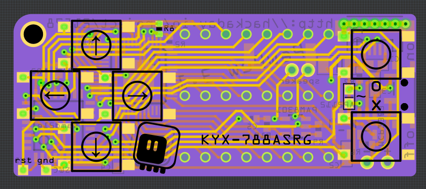
Then I went and tried to build a custom CircuitPython firmware for this board, and it turns out that it's relatively easy to remap the pins — so I moved the pins around a little, to free the PA02 DAC pin. Some more experimenting, and it seems I can free up enough room by removing unused modules to include the audioio module. Together with the free DAC pin that means I can have some sound.
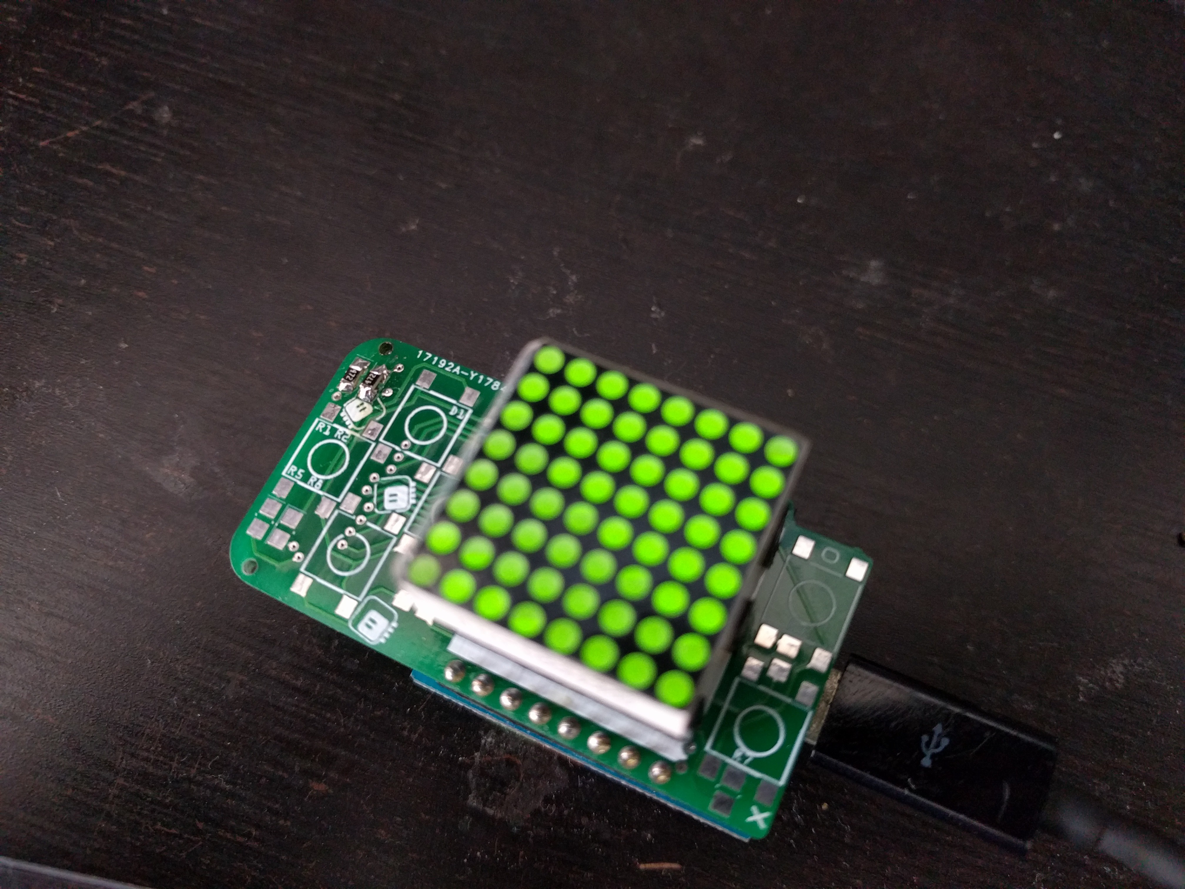
So I moved the traces for the display to pack them a bit more densely, and sqeezed a small PAM8301 amplifier in there, and a pair of pads for soldering an SMD speaker. The end result looks something like this:
![]()
I also remembered about a recent hack with Trinket M0 that expands the available flash memory with an SPI flash chip. That would actually solve a lot of problems for me, and a quick check revealed that the pins that are being used are indeed free in my design. However, there is physically no room for a SOIC-8 chip in there.
I might actually try and go for the sandwich approach, with a second PCB acting as the back plate for the whole device — the cost of the PCB would be negligible, and I would have so much more room for everything...
-
PewPew 3.0 Standalone
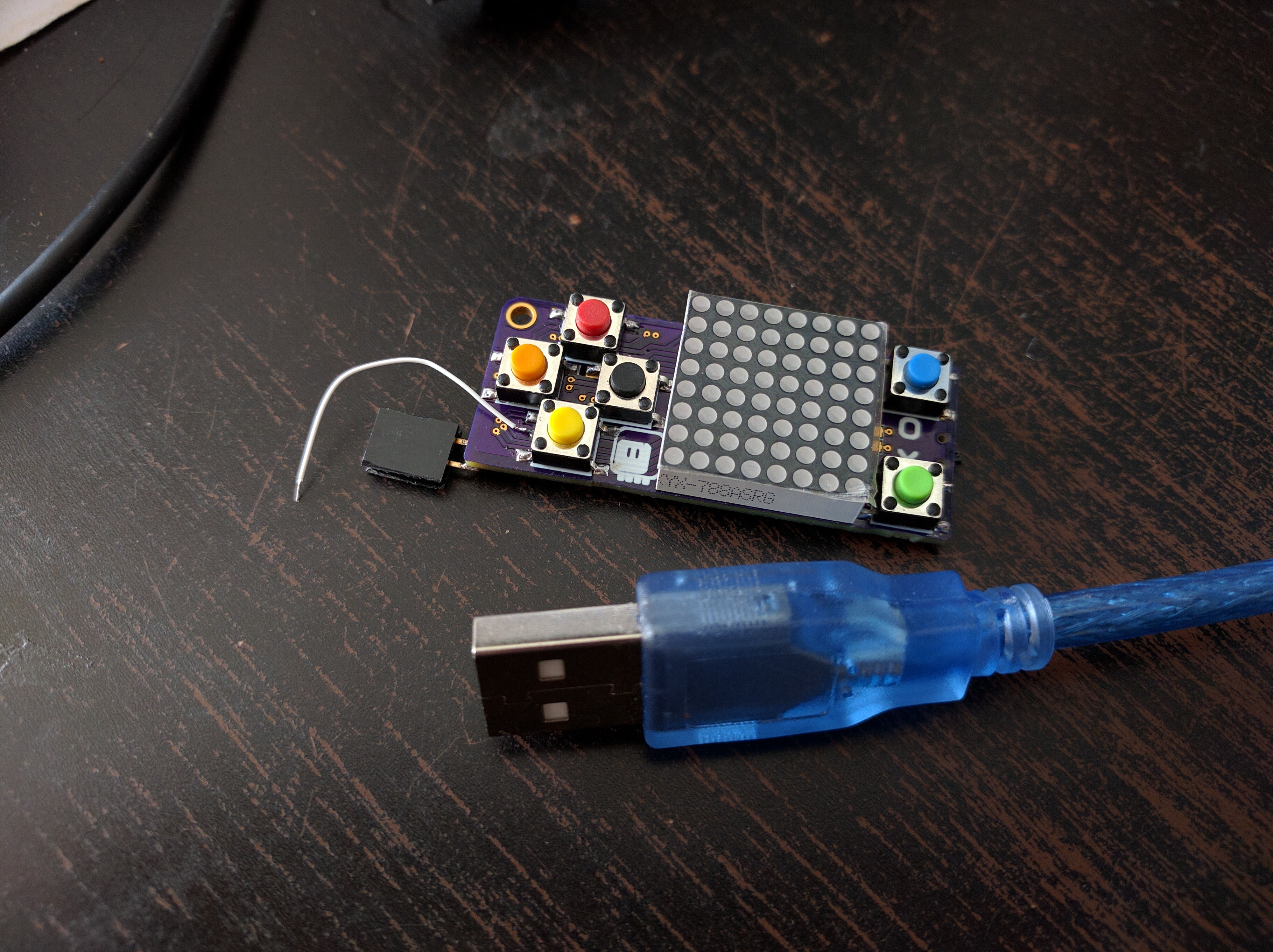
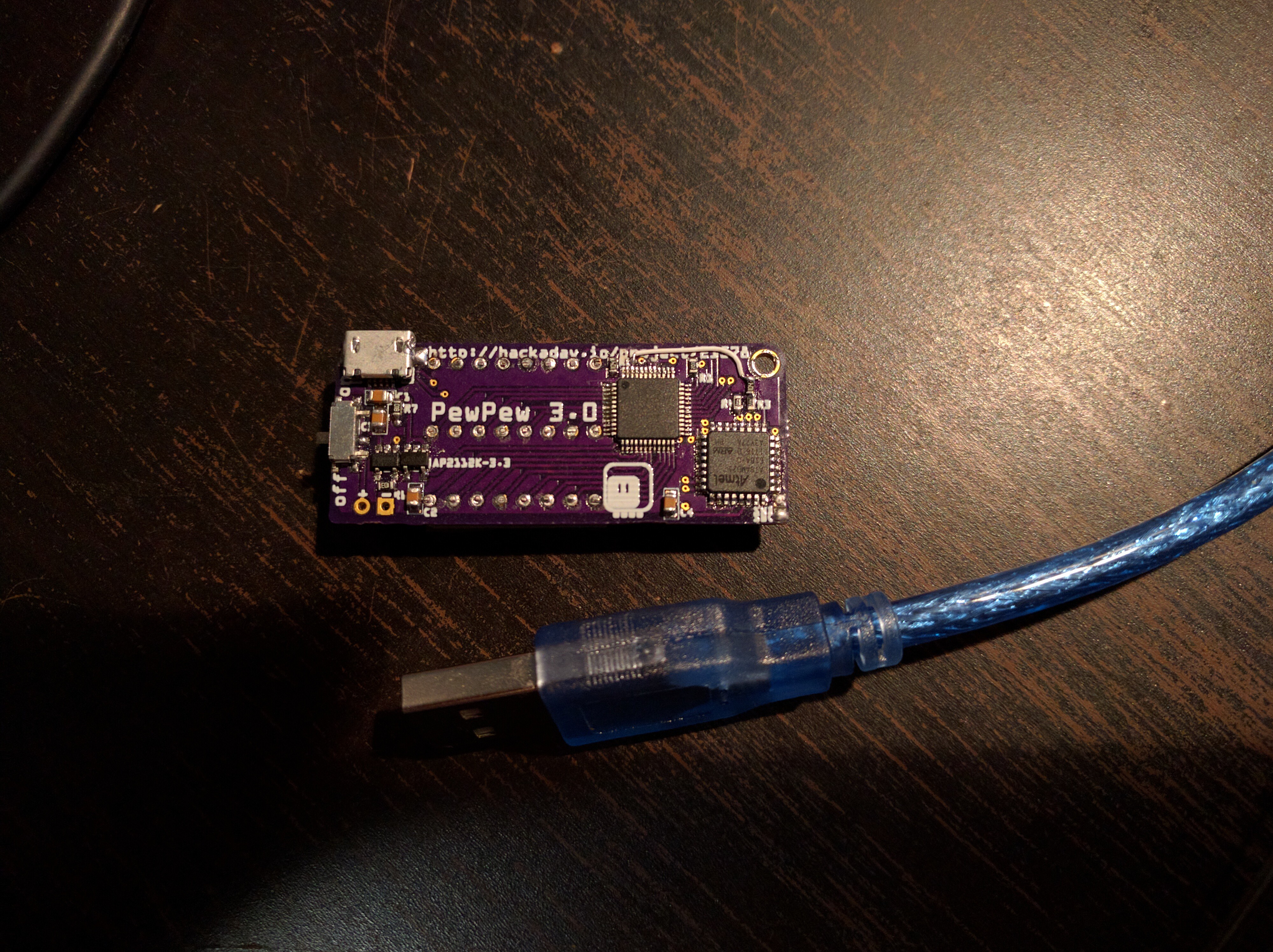
09/22/2017 at 22:54 • 0 commentsAfter my last experiment with the homebrew Trinket M0, I designed and ordered a board for PewPew that has its own Atmel SAMD21E chip on board. It arrived today, and i assembled it and it seems to be working! I was able to flash the UF2 bootloader and CircuitPython on it, and to light up a couple of pixels on the display — I still need to re-write the pew.py library for this platform. I'm especially worried about button handling, since CircuitPython doesn't have any interrupt support. In the worst case I might need to write the library in C and compile it into my own fork of CircuitPython.
![]()
If it does come to that, I will probably also remap the pins, to use ones not available on the Trinket, and to free up the DAC pin for sound — adding a small amplifier and speaker would be great then. For now the design is a little bit random, and I had to add one wire where I missed a pull-up resistor. I expect to make more versions, and to gradually clean up the design and arrange all the elements properly.
![]()
I'm also not happy with the location of the USB port, and generally with how you touch the elements with your fingers while holding this. I might actually get back to the "sandwich" design with two PCBs, so that the back of the bottom PCB could be completely clean of components, and the battery could be hidden in between.
-
Tetris
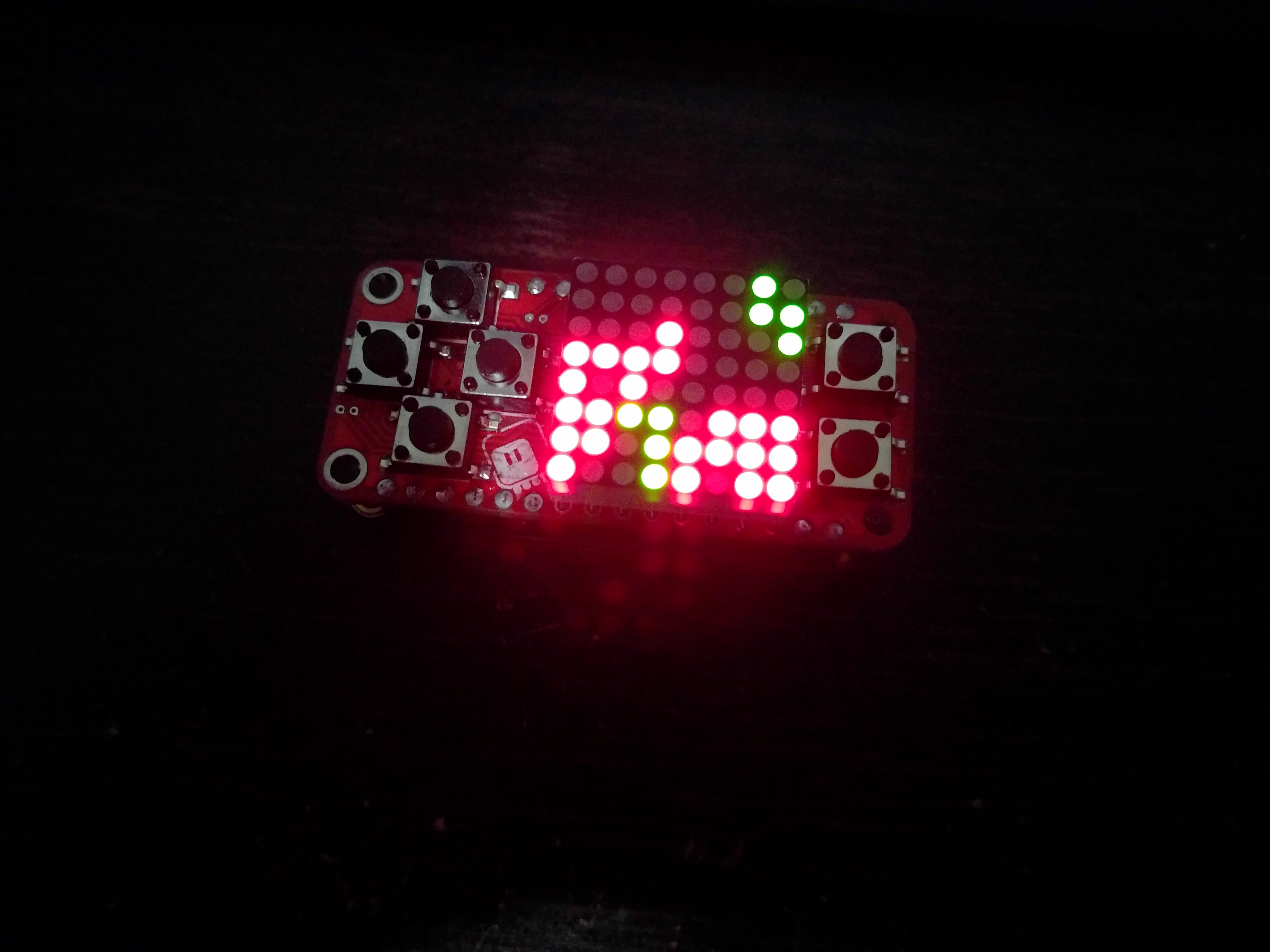
09/16/2017 at 22:44 • 0 commentsThis took me a little longer than I expected, but finally I wrote a Tetris clone in just under 100 lines of code. The game is challenging even at slow speed, because with the small screen you only have 6×8 blocks to fill (2 columns are used for displaying the next brick).
![]()
Next up Boulderdash and Sokoban, and then maybe Arkanoid?
-
Homebrew Trinket M0
09/15/2017 at 20:47 • 1 commentThe PewPew Lite FeatherWing is released and on sale on Tindie, so time for the next steps. I'm still working on the documentation and games — I hope to actually publish something this weekend. In the mean time I also started working on the full — not "lite" — version of PewPew again. It will have the IS31FL3733 chip for driving the LED matrix, so there will be more colors available (but the library will be backwards-compatible), and it will have a microcontroller chip on it for handling the buttons and possibly sound. But what microcontroller?
So far I have built one prototype with the ATmega328p on it, working as an I2C slave, providing the button handling and some simple sound generation. The sound part is actually the main difficulty, and I'm not very happy with what I got there. So there is a possibility for using different chips.
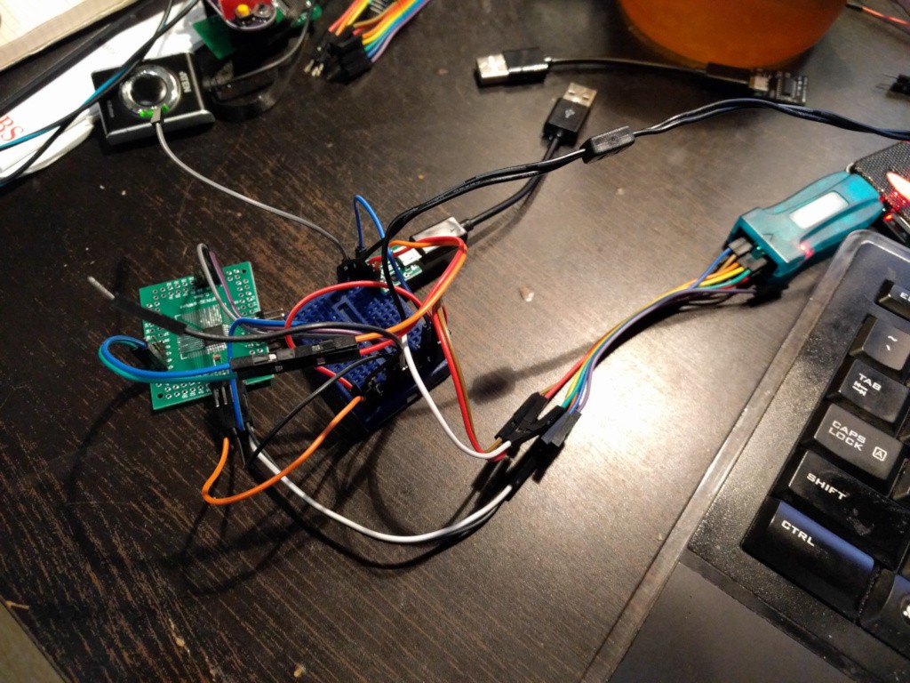
Today I spent half a day experimenting with an ATSAMD21E18 chip — the same as on the Trinket M0. I ordered a bunch of them recently, and I decided to try and run CircuitPython on them. Why did I choose that one, and not the other chips that are used in the Feather M0 boards? Because Trinket M0 doesn't have an external oscillator, and the only part that is actually required on it is a tiny little capacitor. So I connected all it all up:
![]()
Two power pins, two grounds, D+, D- and GND for the USB, and SWD, SWC and GND for the STLink-v2. And some wires for the reset pin. There is also a small capacitor between the VCORE and GND pins there — it has to have short traces, so I added it directly to the pins with some wrapping wire.
Now, to burn the bootloader. You will need to compile the bootloader itself, the sources are at https://github.com/Microsoft/uf2-samd21, and you will need to flash it. The makefile in that repo has a "burn" target, but it requires a specific version of Arduino to be installed, and some hacking with the OpenOCD configuration, so instead I used https://github.com/adafruit/Adafruit_Adalink. The rest of the day was spent trying to get it all to work, not realizing that the step I'm missing is wiping the chip. So start with that:
adalink -v atsamd21g18 -p stlink -wThen edit the "uf2.h" file to disable some features for the bootloader (because they won't all fit), and compile it with:
make BOARD=trinketThen take the "bootloader.bin" file you find in the "build" directory, and do:
adalink -v atsamd21g18 -p stlink -b bootloader.bin 0This at least worked for me, though I did run the "make burn" script in that bootloader's directory previously, so it's possible that it set some fuses on the chip too, and may be required.
After doing that, I connected the USB port, shorted the reset wires, and had it appear as a USB disk. I then copied the "update_bootloader.uf2" file, to make sure all the fuses are set correctly, reset it again, and then copied the CircuitPython file to it. Voila, it works!
Next up will be some testing of the pins, and possibly figuring out how to add my own pin definitions to CircuitPython, so that I can use more GPIOs.
-
Maker Faire Zürich
09/11/2017 at 11:11 • 0 commentsWe had a maker faire here in Zürich this weekend, and I was showing off some of my projects there. Of course I took the PewPew Lite boards that I had with me, and let everyone play with the prototypes. I also sold all the kits I had assembled, but one, even though I didn't advertise the fact that I was selling them, and I was very careful to only sell it to people who are genuinely interested in it, and not just getting goaded into buying them by their children. Some observations:
- The fact that it's not a standalone thing, but that they would need to go and buy something from another shop is a bug turn off.
- People didn't seem to mind the price as much, even though I was very careful to point it out.
- The fact that you have to assemble it wasn't bad, it did work well for filtering out the people who just wanted a toy.
- More than tutorials, I need a workshop plan for this. I got at least three tentative offers to run a workshop.
- Everybody much preferred the red PCBs over the yellow ones. I guess the red ones are faster.
I also had four prototypes on my table for people to play with. Some more observations:
- Adults didn't need instructions on how to play snake. Children did.
- Children tried to control the device by touching the screen. Buttons were something strange to them.
- I really need to add a software restart to the firmware. Switching the device off and on is too cumbersome.
- I need a better source of good power switches. One of them broke.
- The battery really lasts whole day, even though it's only 100mAh.
- The whole thing is robust enough to survive being dropped, thrown, stepped on, etc. — the only breakage is the one power switch.
- The buttons are a little hard to press for the really small children. But I'm not targeting this to little children, so I'm not sure if I should be panicking over this.
All in all, I've very happy with the field testing, though I'm a bit nervous now for problems with the kits that the people have bought. I'm going to work on the documentation now to make it even more clear and to make it easy to start with this.
-
The Store is Live
09/07/2017 at 21:26 • 1 commentYou can order the PewPew Lite boards from the Tindie store now!
The link is here: https://www.tindie.com/products/deshipu/pewpew-lite-featherwing/
So far there is only one game for it, Snake (not the same that was written the last PyCon PL sprint, this is a much simpler code), and I'm still writing the tutorials, but the first four boards are there.
-
More Quality Control
09/07/2017 at 00:13 • 4 commentsI decided to assemble one of the "production" boards I made — that is, solder the pin headers and the matrix and plug it into a feather. Sure enough, there are problems. The left button doesn't work, and one of the columns doesn't have the red color.
So I started debugging.
The button problem turned out to be due to a broken trace on the board — they claim they do continuity testing at Seeed, but apparently this one somehow slipped through. Adding a wire solved that.
The column must be a short somewhere, because adding wires doesn't help. I suspect it's a short with a via under one of the buttons. I will try to remove the buttons tomorrow, and see.
But that made me realize that I really have to test the assembled boards somehow before I send them. The hot air soldering is very fast and convenient, but it's not as reliable as doing it with a soldering iron, and sometimes I have to touch it up a bit afterwards.
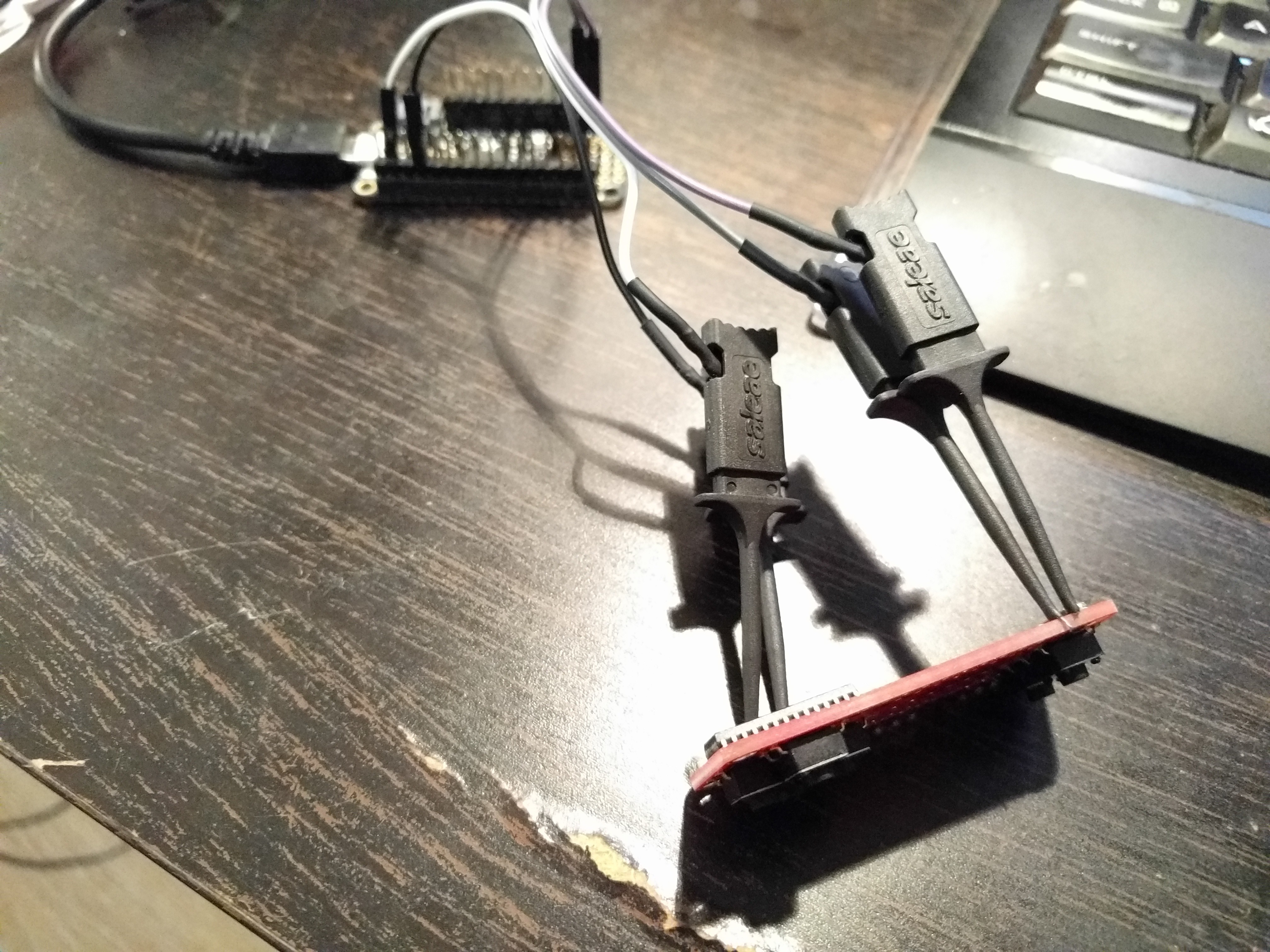
There isn't really much I can do with the matrices without soldering them (and I can't solder them before the headers are soldered, and I can't solder the headers because that would make the whole thing hard to ship), but I have already tested them separately, and there is very little chance of a problem with those connections. But I can at least test that the chip is properly powered, that the I²C communication works, and that all the buttons work. So I made a small testing jig for this:
![]()
Out of 8 boards that I have soldered so far, one had a broken trace, two had a cold joint that had to be touched up with a hand soldering iron, and one had a short between two of the buttons (the new buttons have a bit wider legs and barely fit in their space). Except for the first one, all of them were easily fixed.
I'm still thinking about some way of possibly testing the matrix connections — maybe I will build something with pogo pins.
-
First Production Boards
09/06/2017 at 14:48 • 2 commentsThe PCBs arrived, and I assemble the first four kits already:
![]()
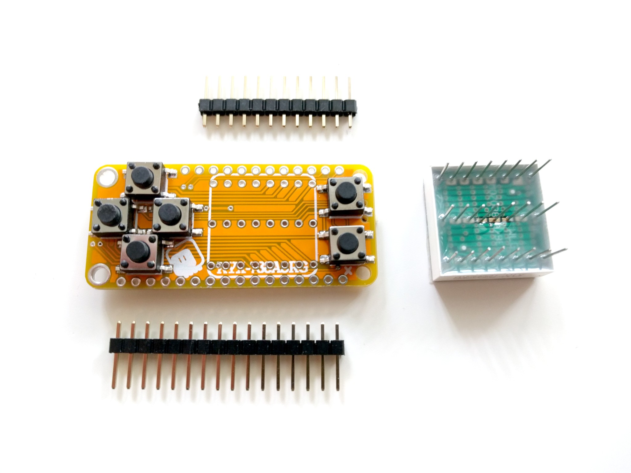
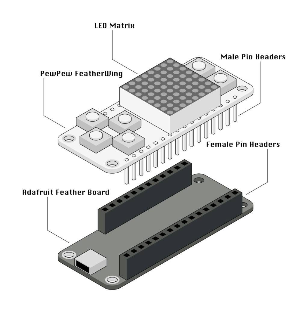
A single kit is 4 pieces: the PCB with all the SMD parts soldered, the two pin headers, and the LED matrix. You will have to solder them all together yourself.
![]()
This is for two reasons. FIrst, it's much easier to ship it without the headers on, second, I don't know what headers you have on your Feather, and you need matching ones.
-
Documentation
08/29/2017 at 23:56 • 0 commentsThe beginnings of the documentation, so far only the library reference, are now uploaded to http://pewpew.readthedocs.io for convenience. More work on the documentation is ongoing, including graphics:
![]()
We also had a sprint at PyCon.PL two weeks ago — I just didn't have time to write about it. Some awesome programmers tried their skills, and wrote a classic Snake game, and a Conway's Game of Life implementation. I noticed some problems with the documentation along the way, and fixed them.
Right now I'm working on the game tutorials themselves, starting with a simple maze game.
-
Quality Control
08/29/2017 at 12:09 • 5 commentsI'm waiting for the parts for the first "production" batch of the PewPew Lite boards — just around 20-30 of them, to sell on Tindie. The LED matrices just arrived from the usual Aliexpress seller, and I decided to use one in an older prototype. Turns out that a green LED in one of the corners is dead.
![]()
Since the pins are responsible for whole rows or columns, it can't be a bad connection. That really made me nervous, so I quickly assembled a testing rig for those matrices and tested all 30 of them:
![]()
I found one more faulty matrix, this time one pixel is noticeably darker than the others. All the other matrices seem to be fine. Caveat emptor.
PewPew FeatherWing
A shield for Adafruit Feather boards with buttons and a LED matrix display, for simple games.
 deʃhipu