Close
0%
0%

Serious desktop CNC mill

On its fourth revision, designed for heavy-duty use machining aluminum and possibly steel

Similar projects worth following
This is my CNC mill. I initially built it to machine PCBs, but it quickly entered a continuous state of feature creep, and is now used primarily to machine aluminum parts. I've completely re-built it maybe 4 times over the past 5-ish years, with the current version being made out of 3/8" aluminum plate. I've upgraded everything to real linear bearings, high-quality ballscrews, and Geckodrives to run the show. The machine is controlled by a BeagleBone Black running Machinekit.

All pieces were done more or less by hand with a knee mill and drill press.

https://sites.google.com/site/dbtayl/cnc-mill

Design: This iteration was properly designed in 3D CAD before being fabricated; previous iterations were just done on-the-fly with the parts I had on hand, with "upgrades" bolted on along the way. I didn't base the design off of any existing mills, though it undoubtedly bears some similarity to a number of them.

Parts: A while back I decided to just "do it right". That means nice ballscrews, real linear bearings, and a whole lot of metal keeping things rigid. Most parts were sourced from eBay, except the metal stock. I got that from my local discount metal store.

Fabrication: I built the whole thing myself, using a mill and a drill press, plus a whole lot of time. I'm really not a great machinist, so setting up the cuts and aligning them took forever. Once the CAD was done, it was probably a couple months of work to get the machine put together and running.

What's been upgraded since the first version: Everything except the steppers (which might benefit from an upgrade, but are mostly fine).

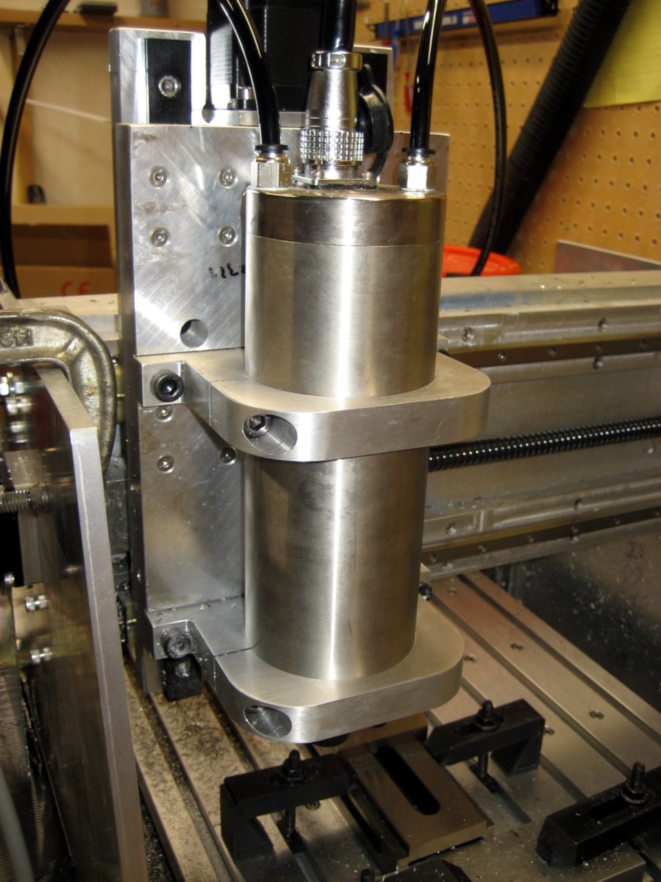
  • Third spindle (Dremel, nicer Dremel, real 1.5 kW spindle)
  • Third Z axis (drawer slides, bushing-based linear stage, custom-built with linear bearings)
  • Third power supply (24V, 48V, new 48V after blowing up the first)
  • Second set of bearings on X and Y axes (drawer slides to linear bearings)
  • Third set of leadscrews (1/4-20 hardware store threaded rod, ACME rod, ballscrews)
  • Second mechanical frame (first one was a cut up tabletop, now 3/8" aluminum plate)

So a long-running project to get to this point!

20170430_cnc-mk4.step

This should be the latest CAD, in a form that just about anybody can use. It should be fairly complete, fasteners notwithstanding.

step - 17.18 MB - 04/30/2017 at 16:35

Download

cnc-mk4.3dm

I THINK this is the most recent CAD; will try to get a STEP file later. It can be opened in Rhinoceros, maybe other CAD packages.

3dm - 31.49 MB - 04/30/2017 at 16:23

Download

20160417_cnc_mk4_wip.png

A picture of the CAD. The final result actually looks pretty similar!

Portable Network Graphics (PNG) - 283.59 kB - 04/30/2017 at 16:15

Preview

  • 1 × Linear motion parts you find on eBay
  • 1 × Machine shop
  • 1 × Way too much time
  • 1 × BeagleBone Black This is the magic that controls it all- it works really well!
  • 3 × Geckodrives If you're serious about building a CNC mill, these are what you want

  • Upgrades! New spindle, coolant

    dbtayl11/23/2017 at 02:36 0 comments

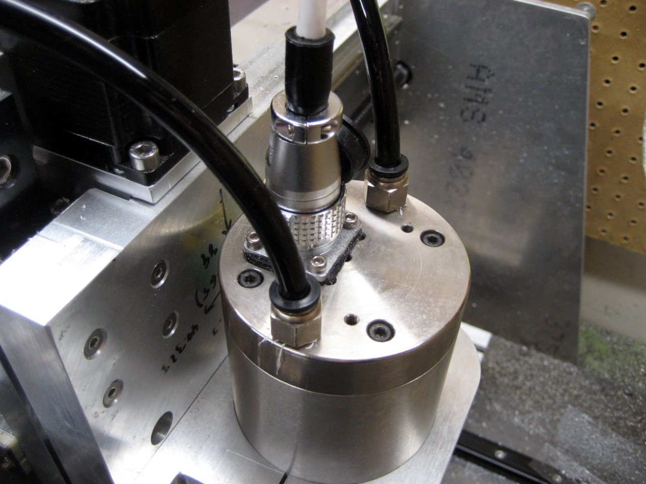
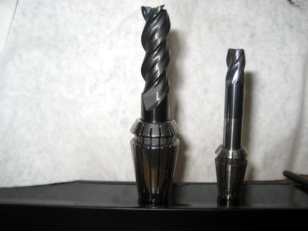
    Time for some upgrades. I got sick of being stuck with 1/4" tooling (lots of fun cutters- dovetail, keyseat, etc.- seem to start at 3/8" shank), so I got a spindle that takes ER16 collets. Now I can go up to 3/8" tooling! Same RPM and power specs, though.

    Tooling comparison:

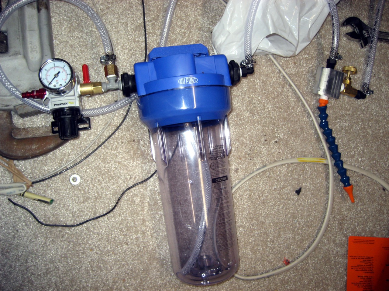
    There's also the new coolant system- more on that later. Basically a pressure regulator, reservoir, mixing block, and a nozzle. A quick test indicates it works really well. I'll be more excited once it's actually installed.


    Maybe eventually I'll actually get back to building stuff instead of building stuff to build stuff...

  • Video!

    dbtayl05/09/2017 at 03:22 0 comments

    I dug up an "old" video- actually machining a piece for one of my other projects here- and thought I'd throw it up here in case anybody found it interesting.

    This is cutting at 24000 RPM with a Destiny Tool 1/4" Viper 2-flute carbide end mill. Feed is something like 3000 mm/min and the stepover is ~0.8mm (I think; I don't recall for sure). Depth of cut is ~17.5mm. I've since found that I can take heavier cuts, but don't have video of that right now.

    I'm not much of a photographer, much less videographer, and I wanted to stay behind the chip shield, so the result is less than stellar. Better than nothing!

  • Just for fun: Where this started

    dbtayl04/30/2017 at 16:08 0 comments

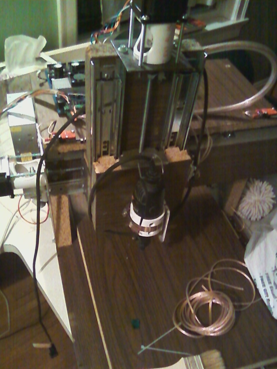
    This is where the project started some 5 years ago... built from whatever was sitting in the basement. No design, just build-as-you-go. The spindle is an old Dremel held on with a hose clamp. The leadscrews were 1/4-20 threaded rod, coupled to the motors with rubber tubing. The whole machine was built out of an old tabletop.

    Amazing what happens if you stick with ti!

  • "Design Your Concept"

    dbtayl04/30/2017 at 16:04 0 comments

    This post is to address how this project has been thought through, to qualify for the 2017 HaD Prize.

    The short answer is that most design aspects have been refined from previous iterations of the mill, so a lot of problems have been caught already. Some of the big concerns:

    • Alignment/being square: This was mostly addressed by fabricating all parts on a mill, ensuring they're square. Alignment was solved in 3D CAD (for the design), and using dial indicators and whatnot when machining the parts.
    • Rigidity: Since this machine is designed for milling aluminum, rigidity is important. I'm far from a mechanical engineer, so my solution was "throw lots of metal at it and how it's fine". So far that seems to have worked. I'd always like it to be more rigid, but it's pretty darn good right now (removing 3 cubic inches/minute of aluminum).
    • Work area: The previous versions wasted a lot of potential work area via dumb design. This iteration seeks to take advantage of the full possible travel of the machine- again, designed in 3D CAD
    • Precision: Previous iterations were... sloppy, in the most literal sense. Lots of backlash, runout in the spindle, and lots of play in the bearings. This version takes great care to use quality leadscrews (ballscrews!), drives, couplings, etc. to minimize these issues.
    • Control: This was fortunately already solved from a mishap years ago- LinuxCNC/Machinekit + BeagleBone Black = awesome. The BBB has realtime units built in that lend themselves VERY nicely to motor control, while the main CPU runs the UI. It's not the fastest UI on the planet, but it works.

    Two big unknowns remain: Chip removal and an enclosure. The first I hope to solve by building an air blast/mister system to blow the chips away from the machine, instead of letting them pile up and manually removing them.

    Enclosing the machine shouldn't be too much of an issue. Right now I've got some plastic pieces I clamp on to mostly keep chips out of my face; it would be ideal to have that extend around the entire machine.

    Adding ways covers would probably be a good idea as well, but I don't have a good solution for that yet. It works without them, but it would be great to not worry about chips getting in there.

View all 4 project logs

Enjoy this project?

Share

Discussions

biały wygrywa wrote 07/03/2020 at 13:29 point

how creating a gcode? I have 3080 but I can create any gcode on linux 

  Are you sure? yes | no

RX HMP wrote 05/05/2017 at 10:24 point

Just come across yours. I will put a build on mine in a minute. Could you pop threw and message on advice ect. Just pop up and say its me with mini mill lol.

Here what I have so far but im thinking get 3axis accelerators and memory. Im total knew and dont think I need them

5 series 2020 I think it may be to weak.

5 series 2040

250mm width and depth
500mm lengh.
M12 lead screws threw depth "c beam?"
M8 leadscrews for the rest.
nema 23
arduino uno
uno cnc or laser or ramps 1.4 break out
8266 wifi "for woreless control"
4988 drivers
1000w 80A power supply "hp cheap 5quid"
uno 2.5 tft with sd "plug n play seller says but need serious advice immediately for suitable tft firmware might try repetier ect.

motor driver break out, dual "extra fans"


You think steel only? no welder, bolt it? or go with the 5 series aluminium? its expensive but im sure steels cheap and advised for this well it is for the nema 23s.

Im wanting to do rc, pcb, pdbs and threading atleast. I want to cut carbon fibre but read allsorts so ive decided on not to.

Pop in im put my pics up now.

  Are you sure? yes | no

dbtayl wrote 05/08/2017 at 04:24 point

I'm not really sure what you're asking. I'd suggest going and reading everything you can on mill design. The motors don't care how you control them, so you can figure out the mechanical and electrical pieces essentially separately. Not sure I can help more than that- it's all out ther. You can read all I've gone through at my main site ("Main website" link at the top)- maybe that will help.

I will say that machining PCBs is a huge pain. If you're set on doing it, at least get a vacuum table. You'll REALLY want it.

  Are you sure? yes | no

Dylan Brophy wrote 04/30/2017 at 17:03 point

You should post some instructions so we can make them too!

  Are you sure? yes | no

dbtayl wrote 05/08/2017 at 04:18 point

I've started writing up a doc, but will undoubtedly get down the rabbit hole and take forever to finish it. Really it's "machine parts as in CAD drawing, screw together", with a whole lot of attention paid to the critical faces (anything that has to be square).

  Are you sure? yes | no

Capt. Flatus O'Flaherty ☠ wrote 04/30/2017 at 16:00 point

Impressive!

  Are you sure? yes | no

Similar Projects

Does this project spark your interest?

Become a member to follow this project and never miss any updates