dbtayl
-
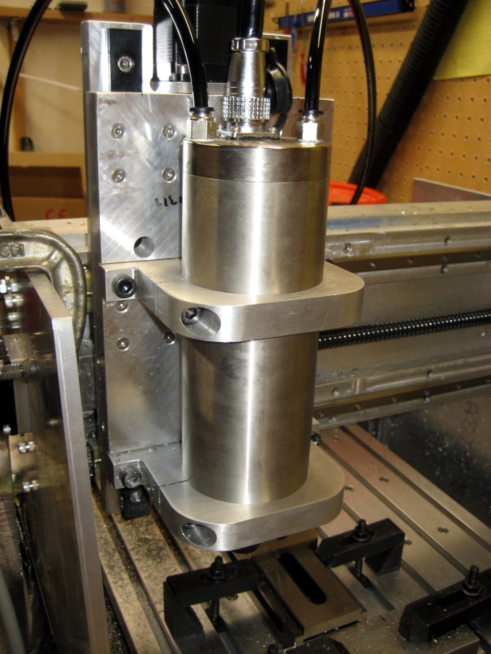
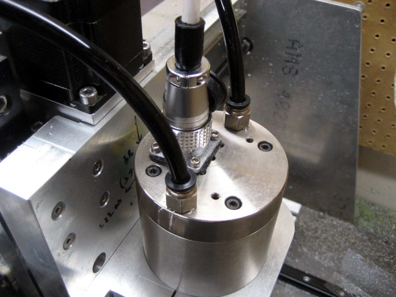
Upgrades! New spindle, coolant
11/23/2017 at 02:36 • 0 commentsTime for some upgrades. I got sick of being stuck with 1/4" tooling (lots of fun cutters- dovetail, keyseat, etc.- seem to start at 3/8" shank), so I got a spindle that takes ER16 collets. Now I can go up to 3/8" tooling! Same RPM and power specs, though.
![]()
![]()
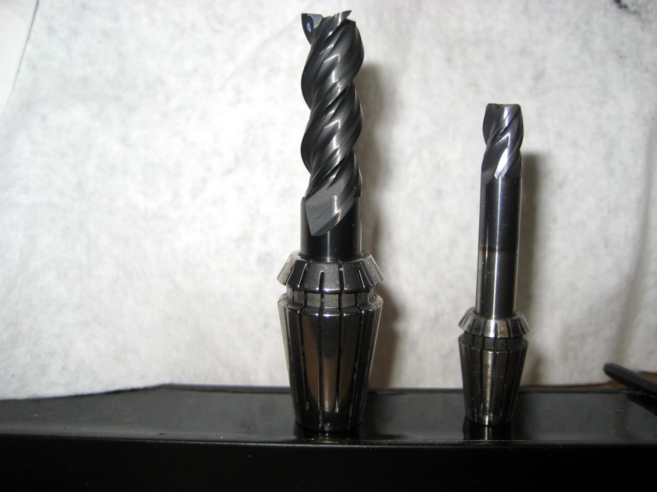
Tooling comparison:
![]()
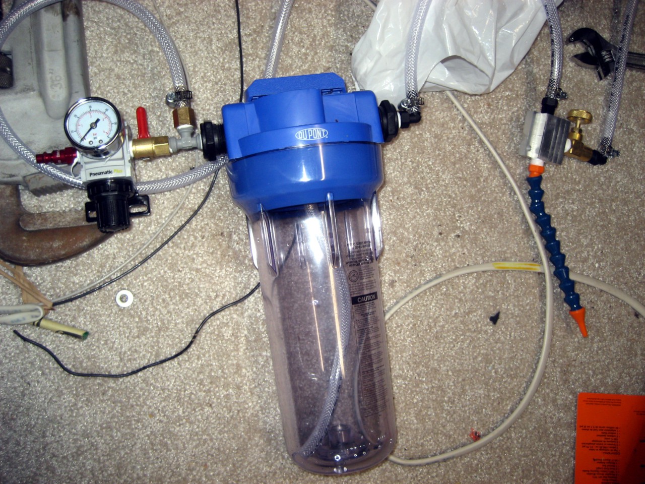
There's also the new coolant system- more on that later. Basically a pressure regulator, reservoir, mixing block, and a nozzle. A quick test indicates it works really well. I'll be more excited once it's actually installed.
![]()
Maybe eventually I'll actually get back to building stuff instead of building stuff to build stuff... -
Video!
05/09/2017 at 03:22 • 0 commentsI dug up an "old" video- actually machining a piece for one of my other projects here- and thought I'd throw it up here in case anybody found it interesting.
This is cutting at 24000 RPM with a Destiny Tool 1/4" Viper 2-flute carbide end mill. Feed is something like 3000 mm/min and the stepover is ~0.8mm (I think; I don't recall for sure). Depth of cut is ~17.5mm. I've since found that I can take heavier cuts, but don't have video of that right now.
I'm not much of a photographer, much less videographer, and I wanted to stay behind the chip shield, so the result is less than stellar. Better than nothing!
-
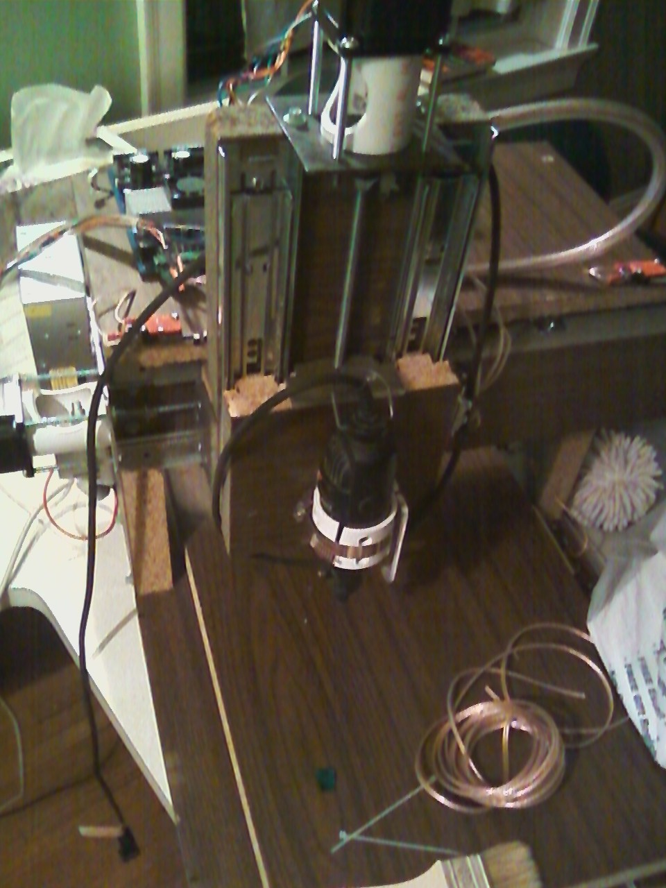
Just for fun: Where this started
04/30/2017 at 16:08 • 0 commentsThis is where the project started some 5 years ago... built from whatever was sitting in the basement. No design, just build-as-you-go. The spindle is an old Dremel held on with a hose clamp. The leadscrews were 1/4-20 threaded rod, coupled to the motors with rubber tubing. The whole machine was built out of an old tabletop.
Amazing what happens if you stick with ti!
![]()
-
"Design Your Concept"
04/30/2017 at 16:04 • 0 commentsThis post is to address how this project has been thought through, to qualify for the 2017 HaD Prize.
The short answer is that most design aspects have been refined from previous iterations of the mill, so a lot of problems have been caught already. Some of the big concerns:
- Alignment/being square: This was mostly addressed by fabricating all parts on a mill, ensuring they're square. Alignment was solved in 3D CAD (for the design), and using dial indicators and whatnot when machining the parts.
- Rigidity: Since this machine is designed for milling aluminum, rigidity is important. I'm far from a mechanical engineer, so my solution was "throw lots of metal at it and how it's fine". So far that seems to have worked. I'd always like it to be more rigid, but it's pretty darn good right now (removing 3 cubic inches/minute of aluminum).
- Work area: The previous versions wasted a lot of potential work area via dumb design. This iteration seeks to take advantage of the full possible travel of the machine- again, designed in 3D CAD
- Precision: Previous iterations were... sloppy, in the most literal sense. Lots of backlash, runout in the spindle, and lots of play in the bearings. This version takes great care to use quality leadscrews (ballscrews!), drives, couplings, etc. to minimize these issues.
- Control: This was fortunately already solved from a mishap years ago- LinuxCNC/Machinekit + BeagleBone Black = awesome. The BBB has realtime units built in that lend themselves VERY nicely to motor control, while the main CPU runs the UI. It's not the fastest UI on the planet, but it works.
Two big unknowns remain: Chip removal and an enclosure. The first I hope to solve by building an air blast/mister system to blow the chips away from the machine, instead of letting them pile up and manually removing them.
Enclosing the machine shouldn't be too much of an issue. Right now I've got some plastic pieces I clamp on to mostly keep chips out of my face; it would be ideal to have that extend around the entire machine.
Adding ways covers would probably be a good idea as well, but I don't have a good solution for that yet. It works without them, but it would be great to not worry about chips getting in there.
Serious desktop CNC mill
On its fourth revision, designed for heavy-duty use machining aluminum and possibly steel