Close
0%
0%

Z80 Computer

Yet another Z80 computer.

Similar projects worth following
Yet another Z80 computer. I've already made one on a breadboard which works. I'm now re-doing it with a CPLD, with the aim to eventually get it onto a PCB. I don't have a name for the project, or any amazingly original goals, except that it should run CP/M.

The Original Project

Many years ago, I had a stack of Z80 based computers — mostly RM 380Zs, and a few Cifer 2684s. Eventually I ran out of space, so I ripped out all the socketed ICs, put them in an empty margarine tub, thew out the computer shells and planned one day to use the ICs to build myself a computer.

Although I now wish I still had the old computers, I can't do anything about that. But I eventually got round to building a new Z80 computer with the parts I had. My initial goal was to build a Z80 computer using only those parts, but I gave in and acquired a few extras — namely, a 4x16 character display, a buzzer, and FT245 USB-serial breakout board and a MAX70x power supply monitor. I initially used a single TMM2016P to give me 2Kb of RAM, but then bought a 512Kb RAM chip instead.

The memory map is divided into 4 16Kb banks, into which you can load any 16Kb page of the 512Kb of RAM, or you can map the FT245 into one of the banks — in fact, the FT245 is mapped into the first bank on startup. If you read from any address in the FT245's bank then WAIT states are inserted until a byte is available (send from the PC on the USB serial port). In this way you can bootstrap the Z80 computer by sending it a programme down the serial line. There is currently no way to send data back up the serial line.

You can send data to IO ports to write to the display or turn the buzzer on and off.

The New Project

I now want to get my Z80 computer on a PCB. Unfortunately I would need quite a large PCB to fit all the components, which gets quite expensive, so I've decided that I'm going to replace all the glue logic with a CPLD. I have created a breakout board for the Xilinx XC95144XL, and, to my surprise, it works perfectly. So now I'm working on connecting the CPLD to the Z80 components, on a new breadboard.

My plan is to be able to run CP/M on the computer when it is finished. It will have at least 512Kb of RAM, 32Kb of ROM (I have the EEPROM, but I'm yet to try connecting it up), a screen, a USB serial port, either an SD card or CF card interface, probably a real-time clock, and maybe some other things such as battery backup.

  • Look who's back

    James Ots10/10/2021 at 20:47 0 comments

    So I was going to do the Retro Challenge this year using an FPGA to implement some kind of 8-bit computer, but I accidentally plugged my laptop power supply into the board and it went pop. So I decided it was about time to dig out my Z80 computer project and see what I can do with it. It was a bit dusty, and so was my memory of how it was put together. This project log jogged my memory a little (although I didn't remember it existed initially!), and the source code for the Z80 monitor and the CPLD glue code helped too, but there was still a lot of gaps that needed to be filled in. Not least the fact that I couldn't remember what power supply it needed.

    So I had to look up the part numbers on the power regulator and discovered that it would run on a 5V supply. A lot of my stuff has been in storage since we moved house, but I did have a 5V power supply. The polarity was the wrong way round, but that was easily sorted on the board. Plugging it in didn't make anything go pop, thankfully, and I also got some flickering LEDs, which seemed to be a good sign.

    The next thing to remember was how to talk to the computer. I knew it was an FTDI chip of some sort, but couldn't remember the details. Plugging a USB cable into it made a ttyUSB0 device show up briefly on my computer before disappearing again. It took a ridiculously long time and a lot of fruitless searching on the internet before I discovered that my Xilinx ISE Virtual Machine was nabbing the USB device to use as a JTAG programmer. A simple click of a checkbox and the interface was working outside of the VM.

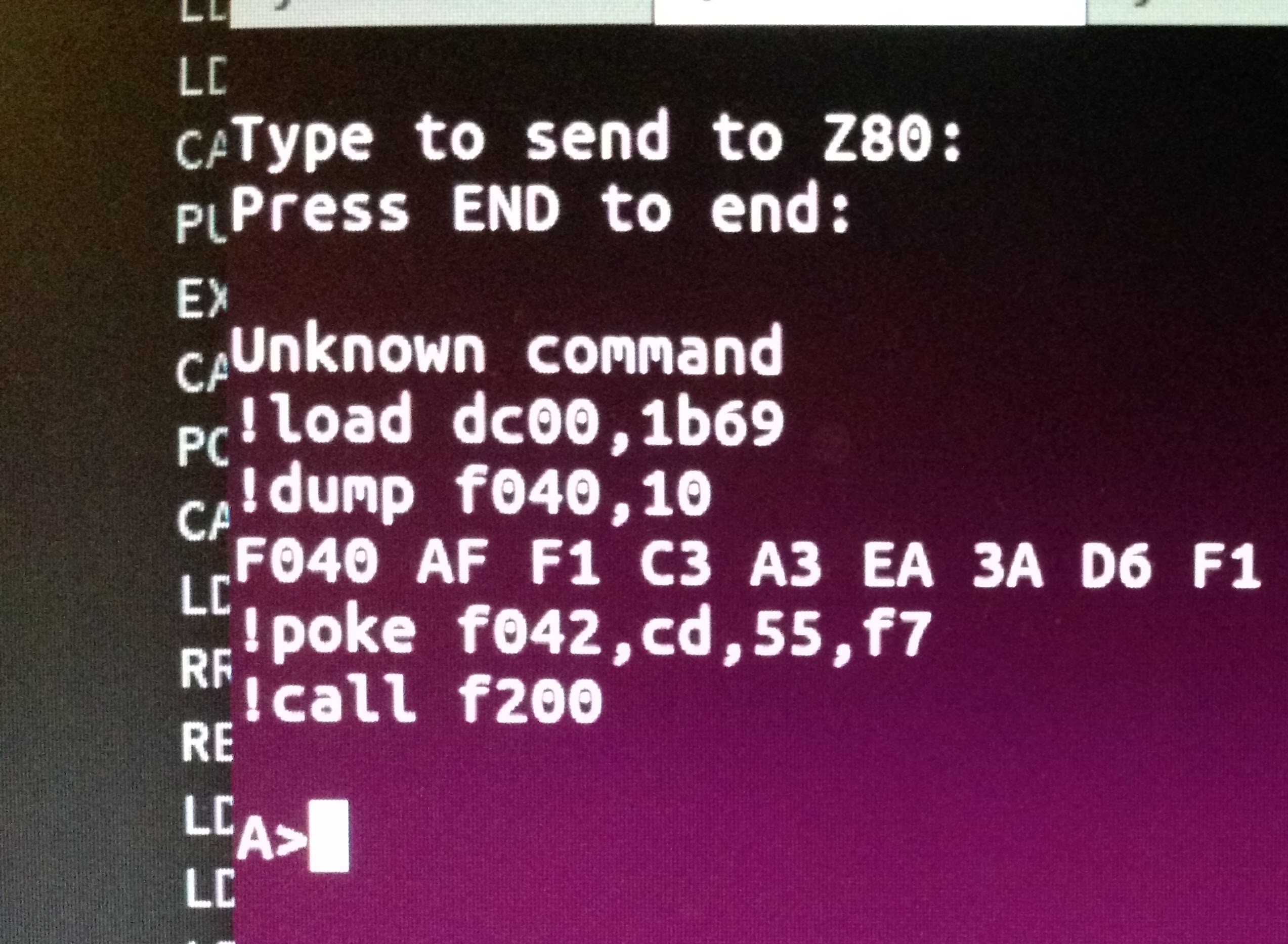
    Then for some reason, no matter what app I used to connect to that device, it was really unreliable at sending and receiving data from the computer. Sometimes I'd reset the board and it would work perfectly, but other times only a fraction of the characters would get displayed. To solve this eventually I wrote my own terminal programme, using NodeJS and webusb, which oddly enough was far more reliable than using screen and libftdi_sio. In fact, it seems to be pretty much rock solid. The other advantage of this is that it can tightly link in with my Z80 Monitor programme so that I can upload new binary files really easily.

    I don't think I have the latest version of the VHDL code for the CPLD board. I've downloaded what I have in my github repository, but I think I must have a newer version on my desktop computer, which is in storage. However, I've rebuilt the version that I have and uploaded it to the board and the computer still works, mostly. The RTC doesn't, and I suspect the SD card won't either, but I haven't got as far as testing that yet. These problems are probably both because they're connected to different pins from those that the CPLD was expecting, so although I've changed the code to connect them correctly, I think I may also have to change something else.

    This time I'm taking far more notes than I did before, and I'm adding more comments into the code so that if I leave it for a few years again I'll have a fighting chance of knowing what's going on next time I come back to it.

  • MAZ: Macro Assembler for Z80

    James Ots07/19/2017 at 21:06 0 comments

    A side project I've been working on for the last ten days is a new Z80 assembler, which I've written in TypeScript and PEG.js. I can't totally remember why I started it, other than a few bugs in ASM80, which I was using, but it's going quite well. It's at a state where it can compile the Z80 monitor for my computer, but there are loads of things I need to add. I also need to properly define how expressions are handled — at the moment it's fairly haphazard, especially when casting types.

    It's currently available on npm, but I wouldn't recommend using it!

  • Playing with the screen

    James Ots07/04/2017 at 22:31 0 comments

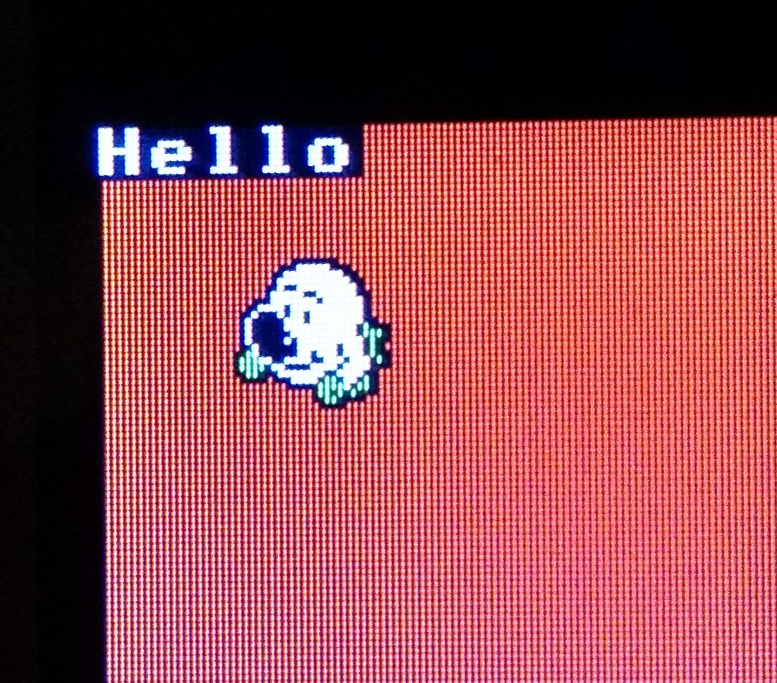
    This evening I was playing with the screen. It really isn't a great screen to use with a Z80, due to the fact that it uses 16 bits per pixel, and there aren't any hardware accelerated commands on it, except for portrait scrolling. But I think it's just fast enough to be able to use. For example, if I draw head (from the game, Head over Heels) on the screen, I can do it in about 2.5 ms, which means I can draw him 400 times per second. Which should hopefully be fast enough to port Head over Heels to my computer if I decide that's not a completely ridiculous idea.

    I'm slightly tempted to use my FPGA board to make an accelerated video controller, but it feels a bit like cheating. If I had enough room left on my CPLD I'd probably add some bits of code to help speed up the screen, but it would need quite a few macrocells, and I don't have many left.

  • Screen

    James Ots07/01/2017 at 15:58 1 comment

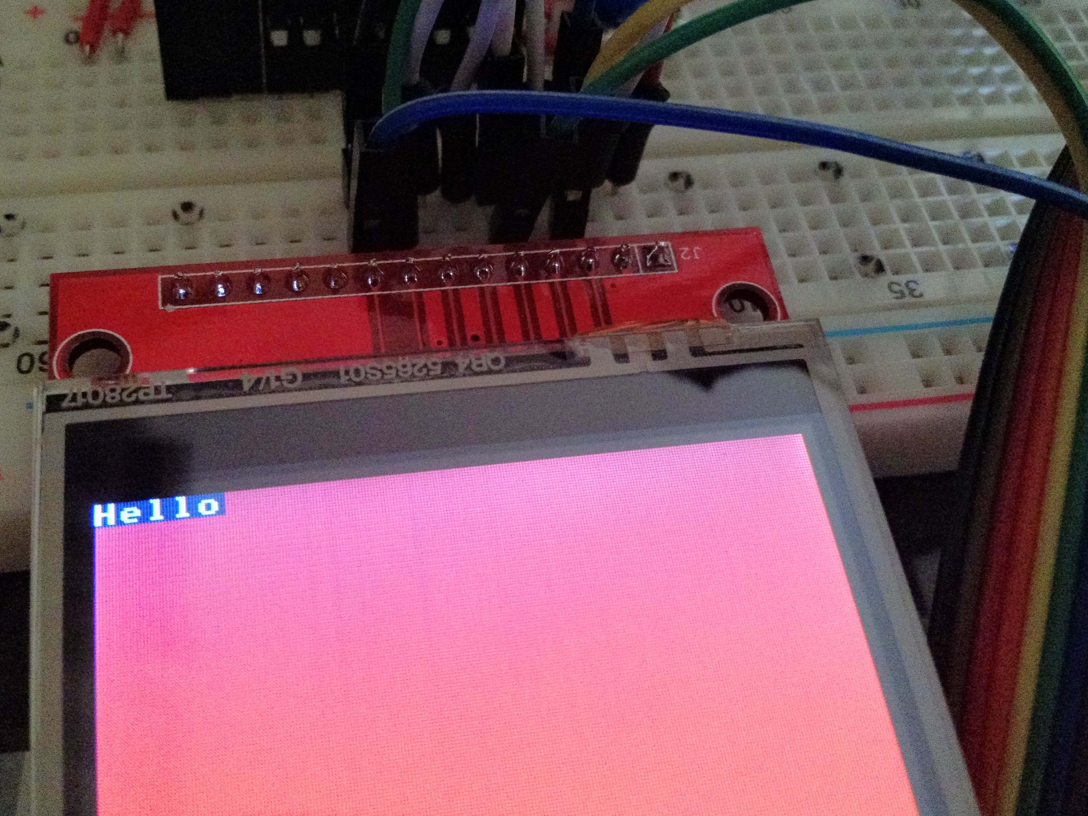
    I now have a working screen. It took a little bit of fiddling, because the ILI9341 lcd controller requires a rather arcane initialisation sequence, so it was, as usual, hard to know if it was my code which was wrong or my wiring. A lot of the time it was silly mistakes in my Z80 code, but it's finally working. And it's very slow — it takes nearly a second to fill the screen with one colour. I can probably optimise my code a little, but not a lot. It'll be fine for small amounts of text, or games where not much moves at a time. But the parallel interface screen should be much faster when it arrives. And when I build this on a PCB and use a 20MHz chip it'll be twice as fast of course. (Actually, I could probably run it at twice its current speed already, if I do some sneaky things in the CPLD…)

  • New Addition

    James Ots06/29/2017 at 11:41 0 comments

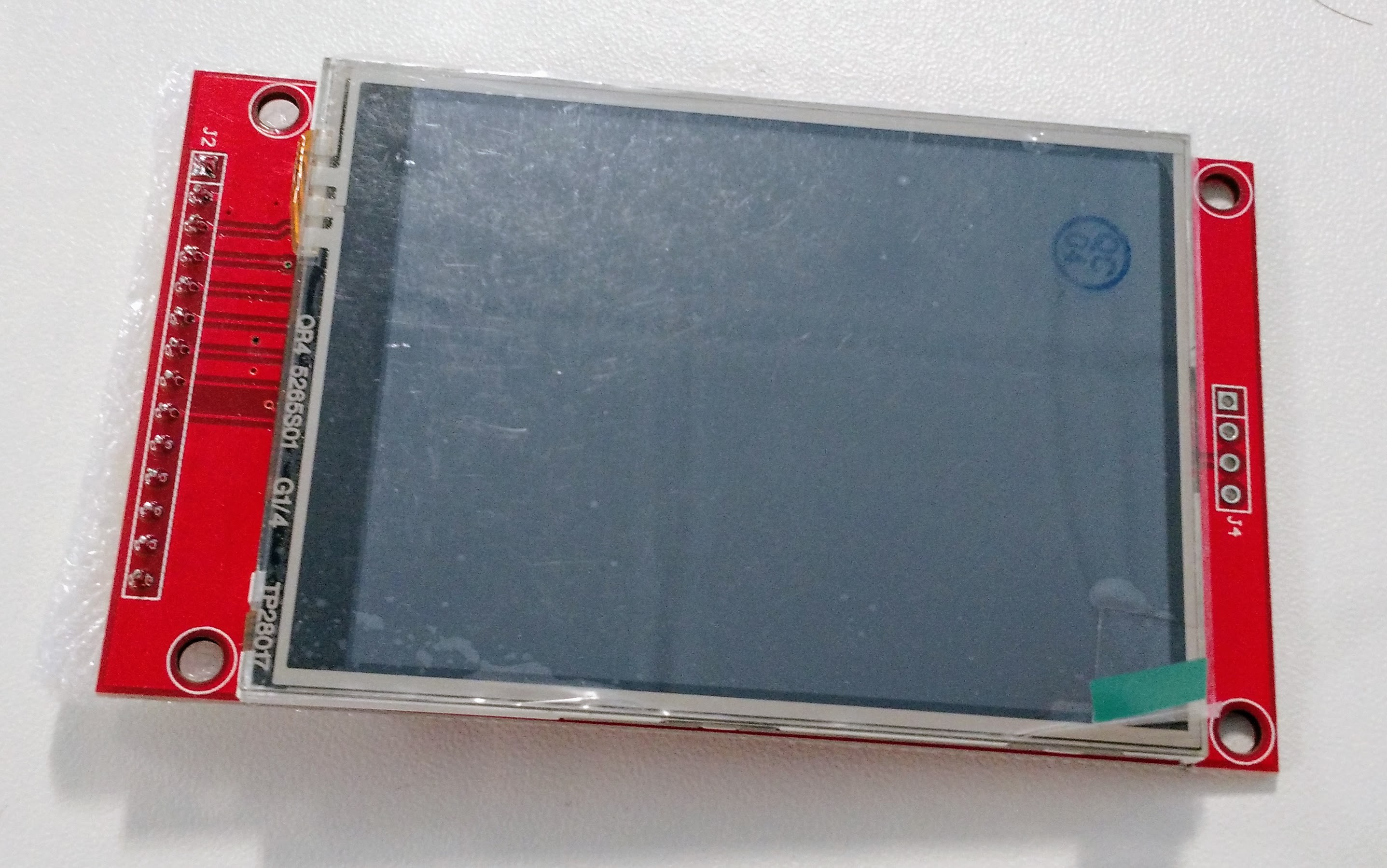
    This just arrived in the post (in less than a week, from China):

    It's a 320x240 full colour touchscreen, which is connected using SPI (both the screen and the touch thingy). I'm not sure if it'll be fast enough to be usable over SPI (I think it should be able do about 3fps), so I also have one on its way with a parallel interface. Maybe I'll end up with a dual screen setup!

  • Boot from SD Card

    James Ots06/28/2017 at 21:08 0 comments

    I added a "boot" command to the ROM Monitor. It loads the first two sectors into memory, and if the last two bytes are B007, it executes the boot sector(s). So I've added a boot sector to the SD Card which loads CP/M. Nice.

  • Warm Boot

    James Ots06/27/2017 at 20:59 0 comments

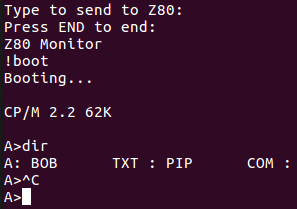
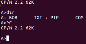
    These screenshots are starting to look a bit boring, aren't they? But they're exciting to me, as they show the progress I'm making with getting this computer to work. Today I did two things. First, I got CP/M to be able to read itself from the sd card so that it can warm boot.

    Second, I added automatic wait states when you try to access the sd card and the SPI routines on the CPLD are busy. I'm not happy with the state of the VHDL code at the moment, but it works, and I think it works correctly because I actually wrote a test for it. It just looks horrible, and is probably using a lot more of the CPLD than it needs to.

    So I pretty much have a working CP/M system. I'm now working on a programme which will download other programmes over the FTDI connection, so that I can actually start doing stuff on this computer, like running an editor and a assembler. Or a C computer, or a BASIC interpreter.

    I also need to write some code which will boot CP/M off the disk initially. I'm not sure yet whether to automatically load the first couple of sectors into memory if there's an SD card loaded, or whether I should have a command in the monitor programme to do it.

  • Note to Self

    James Ots06/27/2017 at 07:45 0 comments

    I just had a thought — I would never need to check the SPI's busy state if I just added wait states when you try to do an IN or OUT while its busy. Then everything could really run at full speed.

  • PIP

    James Ots06/26/2017 at 19:48 0 comments

    Now CP/M actually works. I'm not sure if it was a problem with the SD card loading code, or a problem with the disk parameter blocks. It may have been a bit of both. Certainly, if I create a DPB for a disk which is too big then CP/M won't start, so I currently have it with just an 8Mb disk.

    Yesterday I also fiddled around with the SD card reading and writing code. I managed to speed up writing about 10 times by using an OTIR instruction, and not checking to see if the SPI bus is busy — it never is because sending a byte over the SPI takes a little less time than one loop of an OTIR instruction. I also fixed some bugs, so some of that stuff might also have made CP/M work.

    When CP/M has started, I don't have any files on the disk. One way I could get files there would be to write them directly to the SD card from linux, but I'd have to mess around with the CP/M file format (and get the tools to recognise that I'm only storing 128 bytes in each 512 byte sector). The other way is to load a programme into memory at $100, start CP/M and use the SAVE command to save the memory to disk.

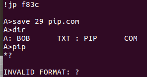
    A slight problem is that if I load anything at $100 it overwrites my ROM monitor, so I added a routine which copies memory from $8000 to $100 and then starts CP/M directly without returning to the monitor. And here we have PIP.COM saved and working. Probably. I'd forgotten how to use PIP as it's about 30 years since I last used it.

  • CP/M

    James Ots06/24/2017 at 22:29 0 comments

    Since I have a working SD Card I decided it was time to start trying to get CP/M to work on my computer. I've written a BIOS which seems to work fine when I test the individual calls, but when I combine it with the rest of CP/M something goes wrong. I put a debugging call in which rings the bell when it gets to a certain place, which caused something to nearly work — I got an A> prompt, at least! But then it doesn't respond properly to commands I enter. I'll just have to keep on debugging.

View all 34 project logs

Enjoy this project?

Share

Discussions

mister35mm wrote 03/22/2018 at 04:19 point

Got any 380z's left complete? 

  Are you sure? yes | no

Peabody1929 wrote 05/23/2017 at 22:46 point

"Point of Interest"

Check these two parameters in the Z80 Datasheet: Vilc and Vihc.  A normal Z80 input pin has a Vih (input high voltage) of 2.2V min.  The Z80 clock input pin has a Vihc (Clock input high voltage) of Vcc - .6V min.  Driving the clock with a TTL compatible signal does not meet this spec.  

  Are you sure? yes | no

James Ots wrote 05/24/2017 at 07:39 point

You're right. But in this case I was trying to get a 'good enough' clock signal using the parts I had., and it's currently working reliably for me. But I'll probably use something else before I build the PCB.

  Are you sure? yes | no

Similar Projects

Does this project spark your interest?

Become a member to follow this project and never miss any updates