James Ots
-
Battery Backup
06/01/2017 at 08:25 • 0 commentsThe real time clock now has battery backup, and the monitor knows how to set the time.
When I added the battery then the computer stopped booting. The FT245R stopped reporting whether it had data available or not. Eventually, after much fiddling, I unplugged the JTAG programmer and it started working. Yesterday I had to plug in the JTAG programmer to make things work.
Something strange is going on.
-
Monitor
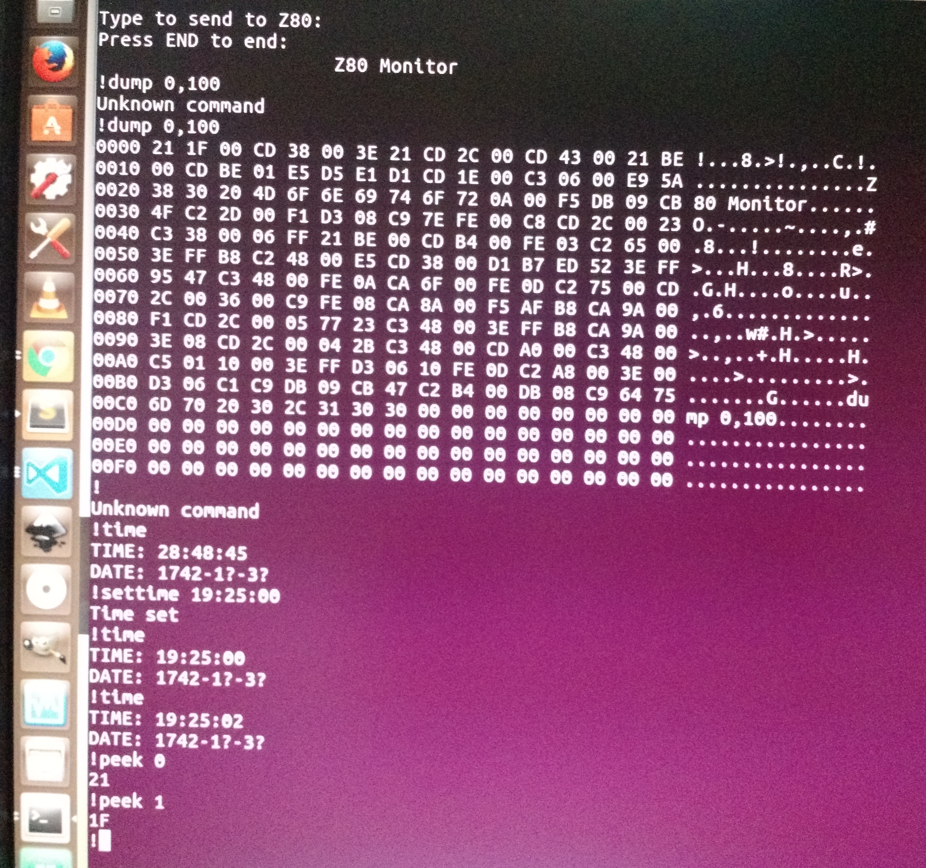
05/31/2017 at 21:19 • 0 commentsI haven't done much hardware for a while, as I've been continuing to work on the monitor programme. I have a few commands implemented so far: TIME, SETTIME, JP, PEEK and DUMP. Things I still plan to implement include SETDATE, POKE, CALL, LOAD, SAVE, ROMWRITE. The Z80 code I've written is not particularly efficient, but it works, and is largely tested. I've been quite enjoying using zat to test my Z80 code — it's much easier to make changes and know that I haven't broken anything. But it's even nicer when I load it into my Z80 computer and it works first time.
![]()
A few things you might notice: The first command is never recognised as it seems to get some rubbish in it. However, I'm not sure where it is coming from — I've added code to clear the input buffer, but it's still getting something extra there. You'll also notice that the date looks rather strange — that's because I haven't written the SETDATE command yet, so the DS1501 just continues to return whatever random data it happens to have in it.
I've had a few weird problems with the computer occasionally. At one point it was starting to make a buzzing noise from the bell whenever the FT245 was in use, which eventually turned out to be the 3.3v regulator. The breadboard holes it was using were a little loose which meant that only 2.8v were getting through to the rest of the breadboard. I moved it to another part of the board, the voltage went back to 3.3v and the buzzing stopped.
Then I was having trouble getting anything received from the FT245. I eventually got it to work again by plugging a USB cable into the JTAG programmer — I have a feeling that having the JTAG programme connected but unpowered was confusing things. I'm not totally sure though.
It certainly makes it difficult to debug when you're not sure if the problem is Z80 code, CPLD code, board wiring, power levels or something else
-
Test Driven Development
05/23/2017 at 21:27 • 0 commentsI started writing a monitor programme for my Z80 computer last night, and got slightly frustrated by how difficult it was to test that my routines were working properly. So I wrote a Test Driven Development tool.
It's very much a work in progress, but the progress so far can be seen here: https://github.com/jamesots/zat
It's written in TypeScript to work inside Jasmine. Here is a brief example:
it('should work', function() {
    zat.compile(`
    start:
        ld a,0
        halt
        org 20
    newstart:
        ld a,$12
        nop
        nop
    breakhere:
        ld a,$ff
        halt
    `)
    zat.run('newstart', {breakAt:'breakhere'});
    expect(zat.registers.a).toBe(0x12);
});
It can also ompile external files and track and respond to IO and memory requests from JavaScript.
It's useable now, but it needs more work — in particular, I want to track IO automatically so that it is easier to write expectations about IO, and it needs to be packaged properly to use from NPM. I imagine the API will change a fair bit over the next few days (or whenever I get to look at this again.)
-
Real Time Clock
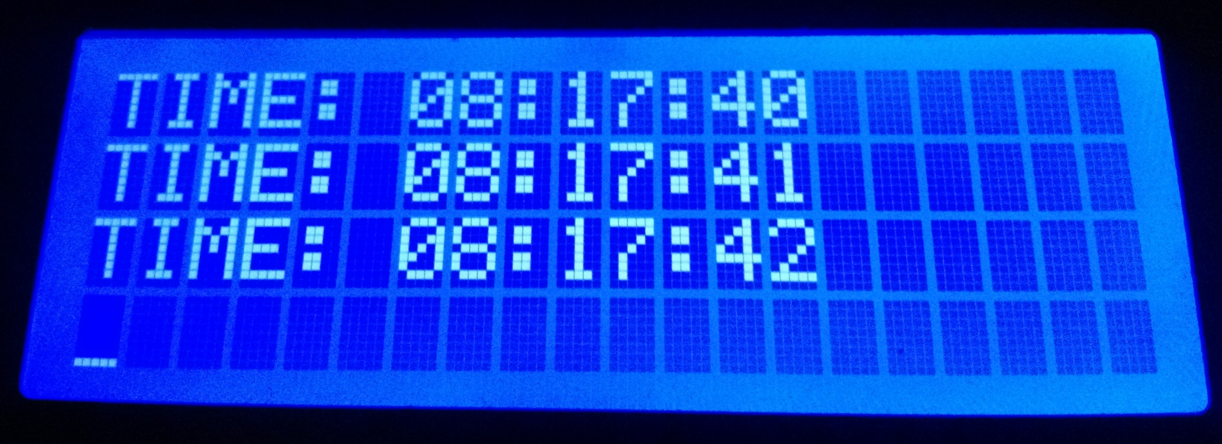
05/21/2017 at 21:03 • 0 commentsI have now got my DS1501 real time clock working. The DS1501 also comes with some 256 bytes of RAM — this won't be accessible in this design as it takes up 16 IO ports and is fairly useless, when I've already got 512Kb of RAM. I haven't wired the battery backup into the RTC yet, so you have to set the time every times the computer starts up.
I've also been trying to get the CP/M version of BBC BASIC running on here. I started building some of the CP/M functions which it uses (as I don't actually have CP/M running, and I was hoping to get a ROM BASIC working), but at the moment it succesfully calls three of my CP/M functions and then dies elsewhere.
![]()
-
Bootstrapping and IO
05/18/2017 at 20:24 • 0 commentsIt's probably about time I mentioned a bit about how my computer's memory is organized, and how I bootstrap programmes into it.
As I don't have a ROM programmer, I had to find some other way to get a programme loaded into RAM. The way I do it is using an FT245R. It has a USB port 'on one end', and on the other end it has 8 data lines, a read and a write line and a couple of signals which indicate whether data is available or the output buffer is full.
When the computer starts up, all memory reads from any address are directed to the FT245R. If no data is available, wait states are inserted until there is data.
In order to then be able to save things to RAM, you have to use OUT instructions to change the memory bank mappings.
I've split the memory into four banks. Which bank is used depends on A14 and A15.
You can choose what goes into each of these banks by sending a byte to one or ports 0, 1, 2 or 3. If the byte starts with 11, any reads from that bank will come from the FTDI, while writes are ignored. If the byte starts with 10 then memory accesses will be to the EEPROM, but I haven't got that set up yet. If the byte starts with a 0 then RAM will be used, and the bottom 7 bits of the byte become address lines A14..20 in theory, although as I only have a 512Kb RAM chip, only A14..18 are used.
Initially the only way to get data in from the FTDI was to map it into memory. However, this is rather a clunky way to do things, so I've now also made it so that you can use an IN instruction to read from the FTDI, and also allowed you to write to it with an OUT. At the moment these are blocking instructions, so I need to also set things up so that you can read the status of the FTDI.
-
A Working Display
05/15/2017 at 18:03 • 0 commentsI have a working display. It was surprisingly straightforward — in the CPLD I just make sure that the E is held low for two clock cycles, followed by being high for four, all while WAIT is low. This is at 8MHz.
![]()
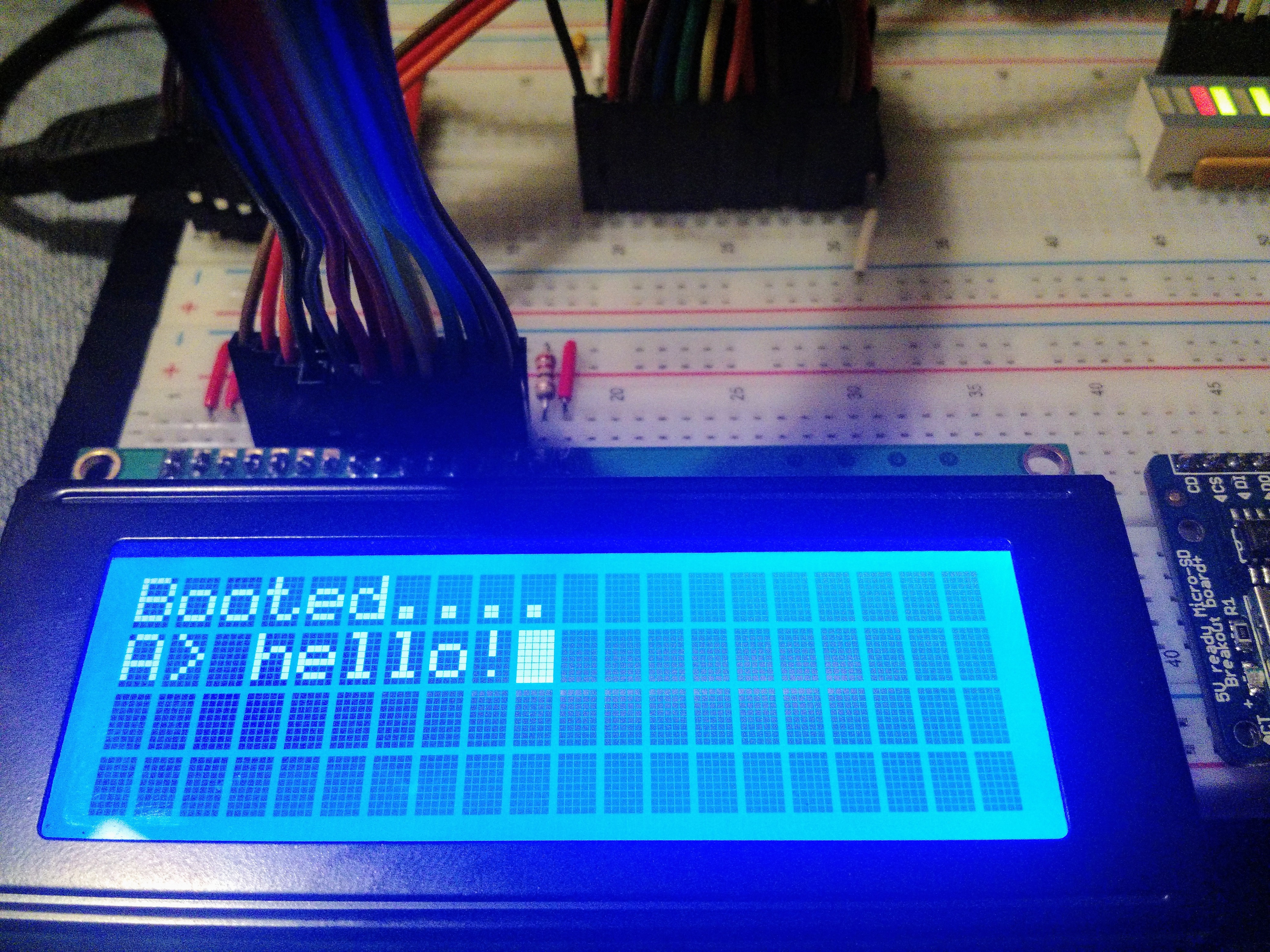
The screen says 'Booted... A>', which makes it look like it's booted up into some kind of OS, but in reality all my Z80 programme does at this point is display characters which it receives from the PC via the FT245R.
Well, I say that's all it does. I got a little carried away, and so there are a few escape sequences too, such as ESC-E to clear the screen, ESC-H to home the cursor, Ctrl-G rings the bell.
Next: The SD Card.
-
Banked Memory
05/13/2017 at 09:12 • 2 commentsI have banked memory working!
And on the way, I have discovered one of the reasons I've been having so much trouble. And it is that the FT245RL seems to get its knickers in a twist when I upload a new configuration to the CPLD, so I have to turn the board's power off and on and then everything works properly again. Not knowing this has wasted so much of my time!
But now banked memory appears to work. I've written a bootstrap programme which loads data from the FT245RL into RAM and then runs that programme. My test programme just switches the buzzer on and off each time you press a key. But it works.
-
Buzzing!
05/12/2017 at 20:54 • 0 commentsThe board still works today. At least at 2MHz — it's a bit iffy at 4. I guess all those long wires don't help much. Also, I noticed that by the time it gets to the left hand side of the board the voltage has dropped from 5V to about 4.5V, so I put some wires directly across there. I also added a buzzer.
I then made the same mistake I keep making — changing more than one thing in the VHDL code at a time, and then not being able to track down where I broke everything. Fortunately I sorted everything out, and was able to send a small programme to the board to turn the buzzer on and off:
ld a, 1
out (6), a
nop  # about a hundred of them
ld a, 0
out (6), a
Yep, that's the biggest programme this computer has run so far.
![]()
-
Maybe working?
05/11/2017 at 22:10 • 0 commentsWhile I'd like to say my Z80 computer is working, after the last few days I'm completely expecting that it will have broken itself again by tomorrow. But for now it works.
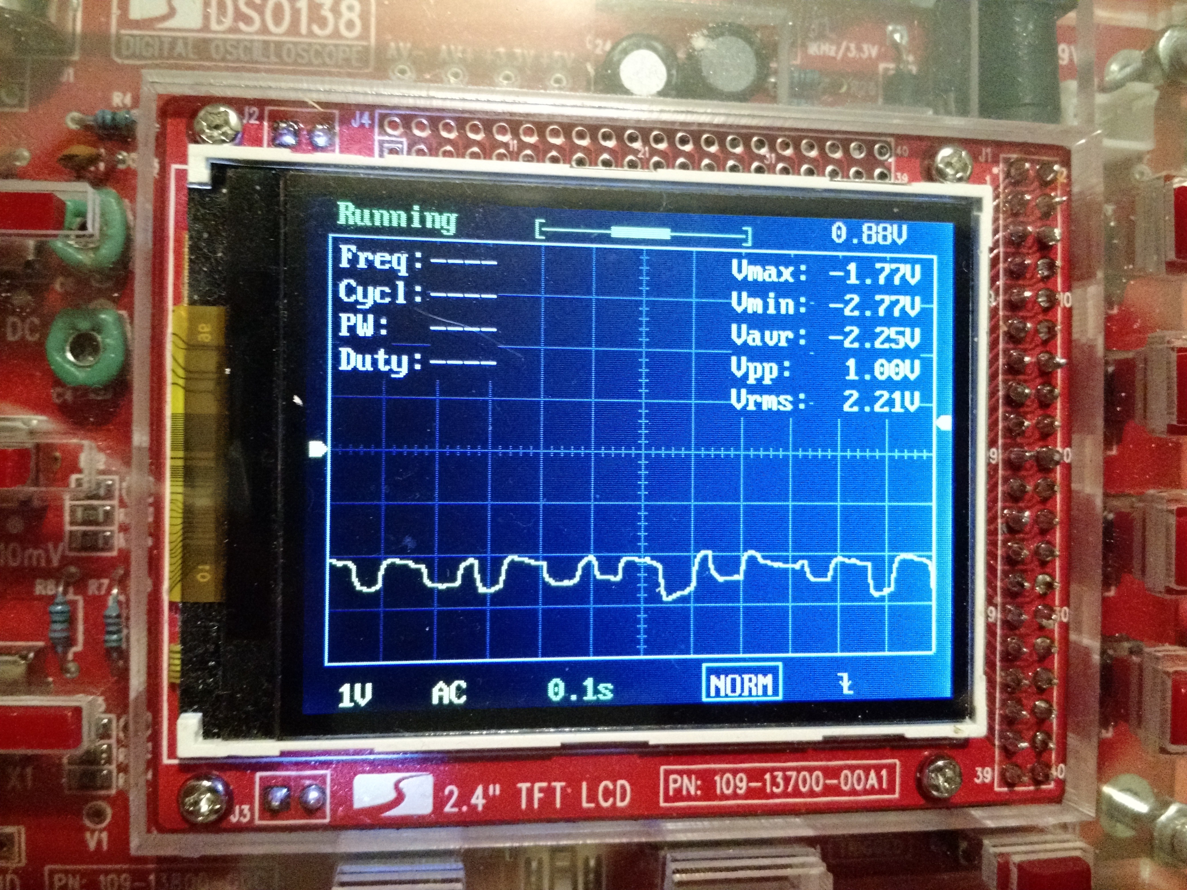
One problem I had was a ridiculously noisy 5v supply. I'm not totally sure what fixed it. I added lots of capacitors all over the breadboard, which didn't seem to make any difference, and I removed a capacitor from the clock circuit. I think it was the capacitor removal which fixed the noise, but I'm not completely sure — especially since I don't really trust my oscilloscope.
![]()
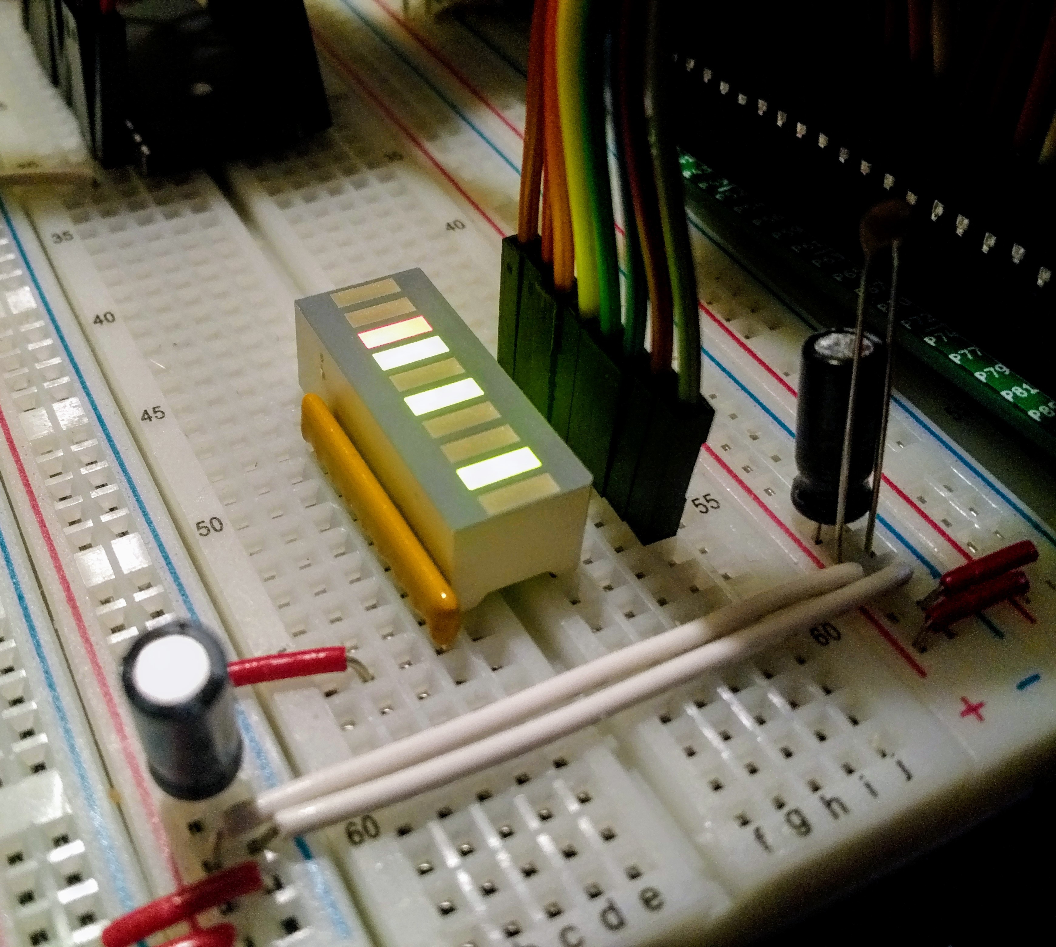
Another thing I've done is added a nice LED array, which is neater than my previous LEDs, and givees me 8 debugging signals without having to do a lot of extra wiring.
As I said, the CMOS Z80 lets me drop the clock speed right down, so I dropped it down to 1Hz. It's really quite interesting watching the various control signals while the CPU runs at that speed, and it was showing that nearly everything was working properly — there were just some weird things happening with the signals coming from the FTDI.
As it's getting late at night, I couldn't be bothered to work out the timing, so I just put the clock speed back up to 4MHz, and now it seems to reliably read data from the PC over the FTDI link.
But who knows whether it wil still be playing ball tomorrow. If it works, I need to try and get the memory bank code working — at the moment it's hacked to always select the FTDI in all banks.
![]()
-
Still not working
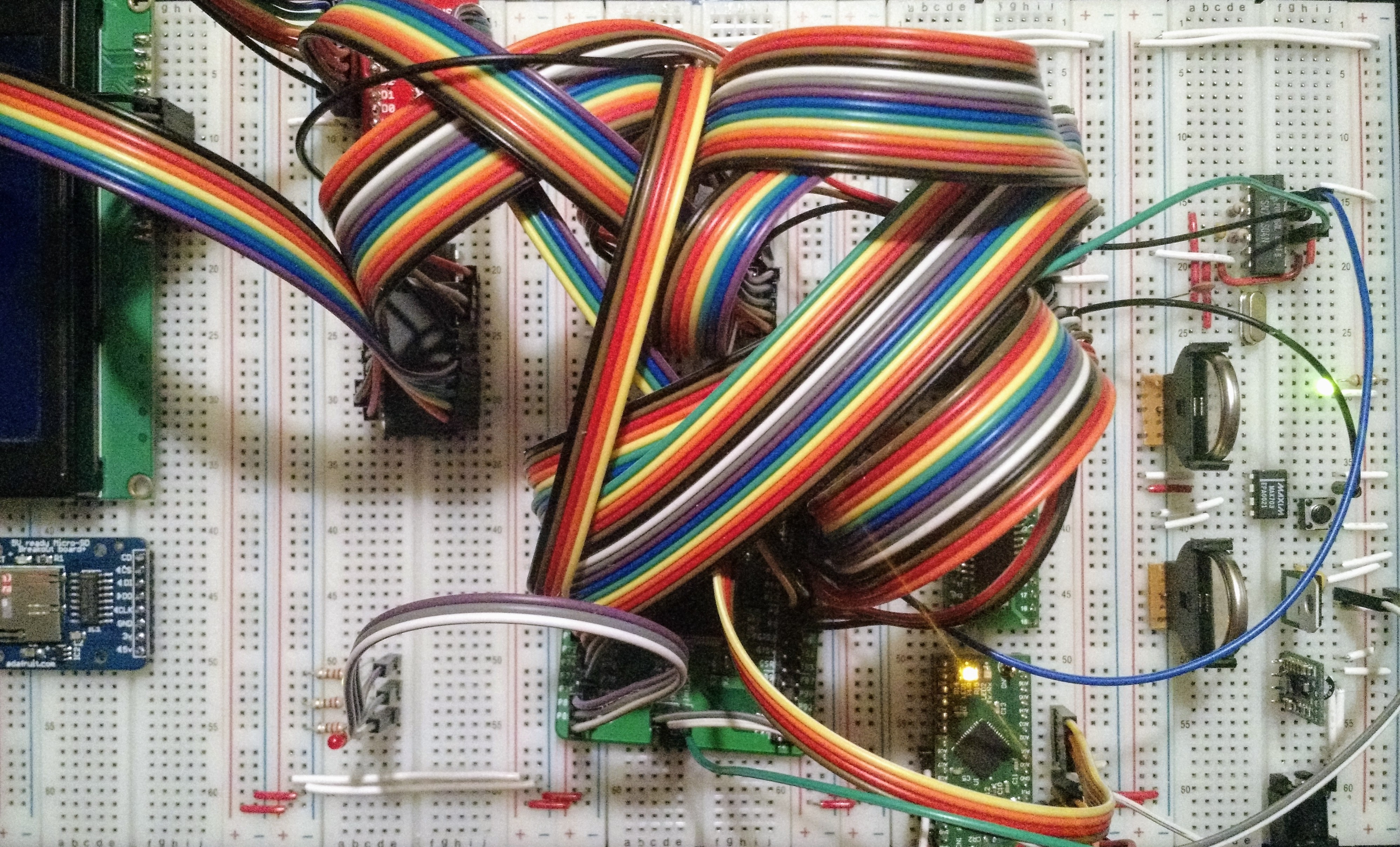
05/10/2017 at 22:04 • 0 commentsSo I've swapped out the 30 year old Z80 for a brand new 10Mhz CMOS one. Which should mean I can drop the clock speed down as low as I like without problems. And I've put a UM232H on the board so that I can power it from the board instead of having the keep switching power supplies when I do any JTAG programming. (There's also and SD card, a real-time clock and two backup batteries on the board, but I'm not using them yet).
And it still doesn't quite work. Oh well, more playing tomorrow.
![]()