Tron9000
-
Demonstration
12/19/2017 at 16:06 • 0 commentsAs promised a video of it working. To follow will be a video describing how the circuit works.
We've had a bit of crap weather here, and its performed precisely how I wanted it to!
-
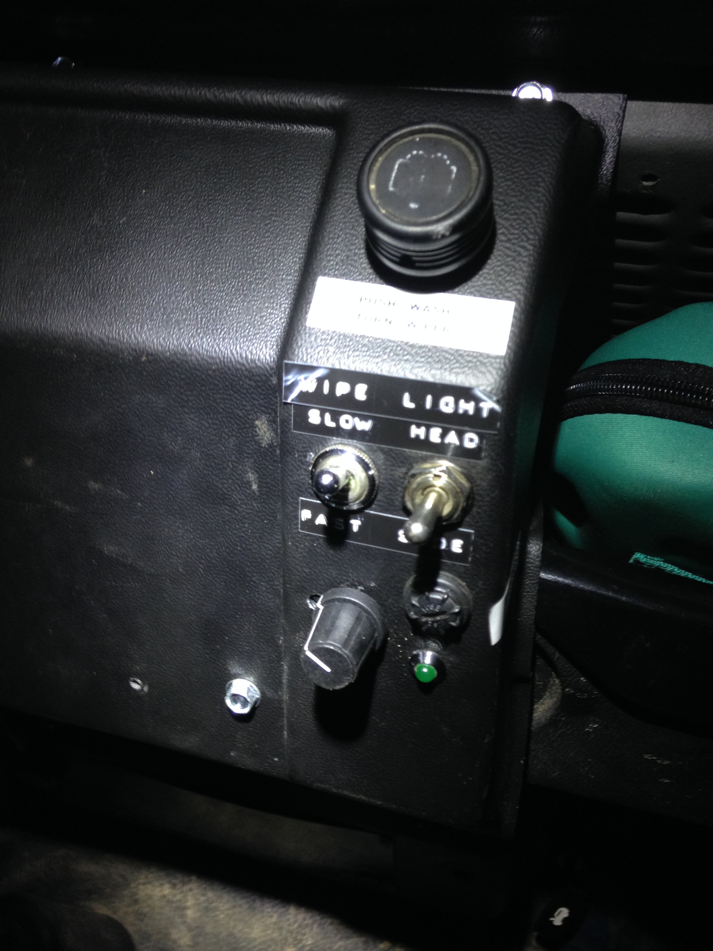
It's in and working!
11/06/2017 at 23:31 • 0 comments![]()
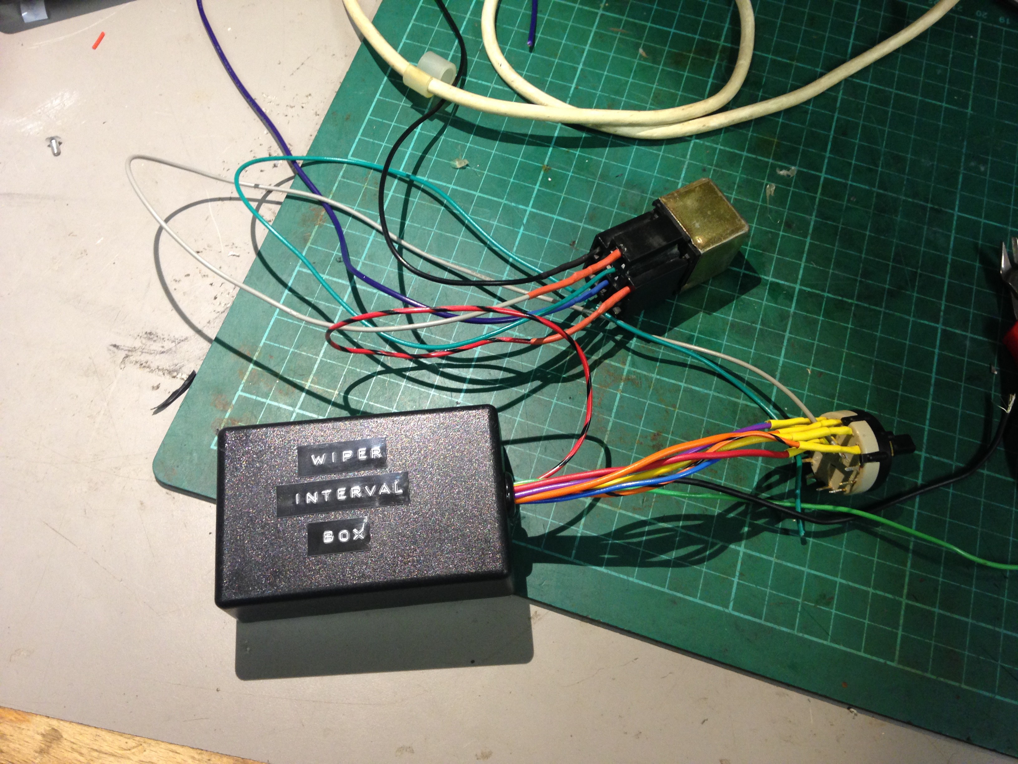
whilst hunting for a problem with My headlights I thought it would be a good opportunity to wire in the wiper interval box.
After some swearing and a
lot of fault finding, I manged to fit it and it works!
![]()
I promise to get a video of it working soon.
-
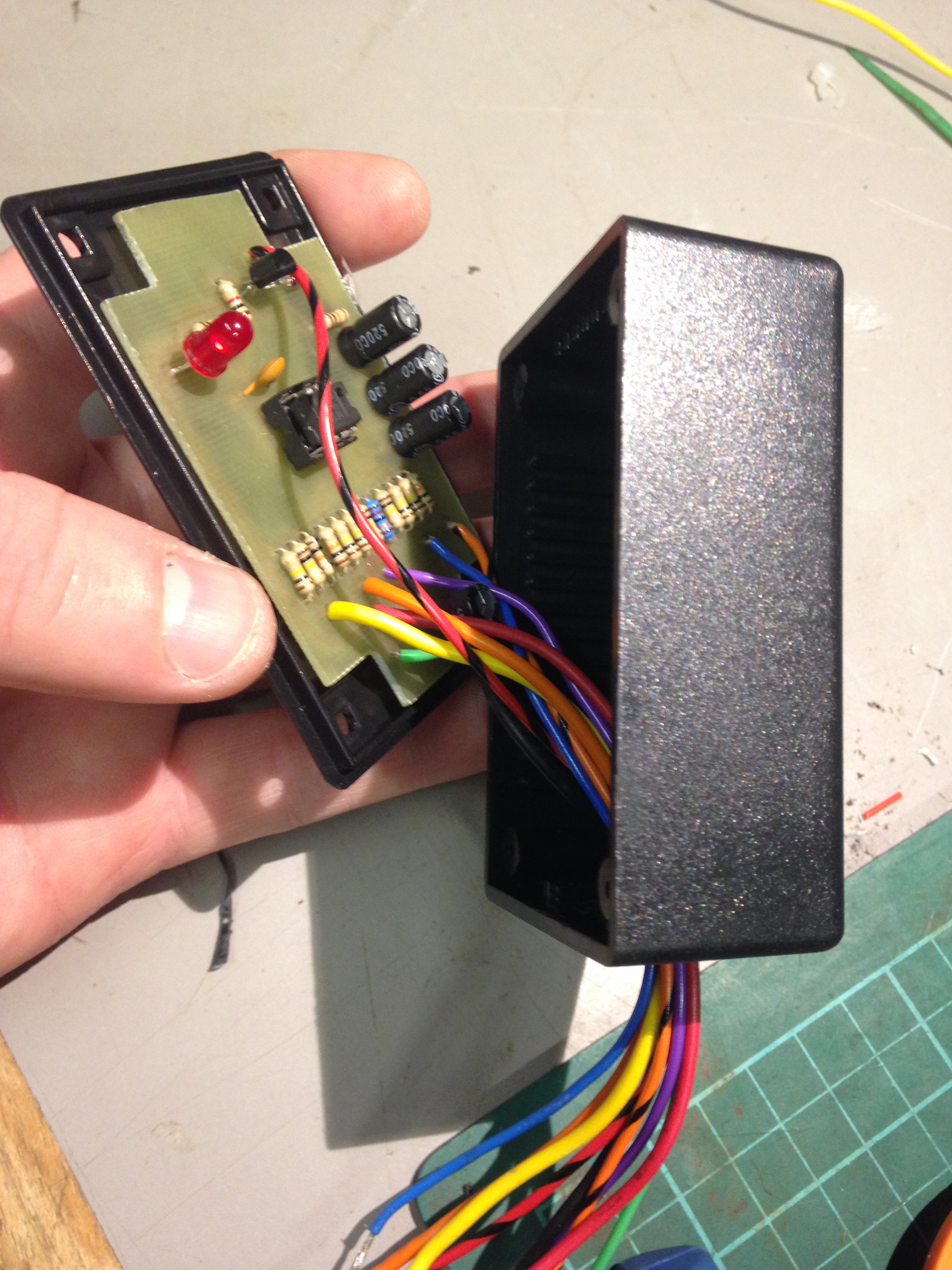
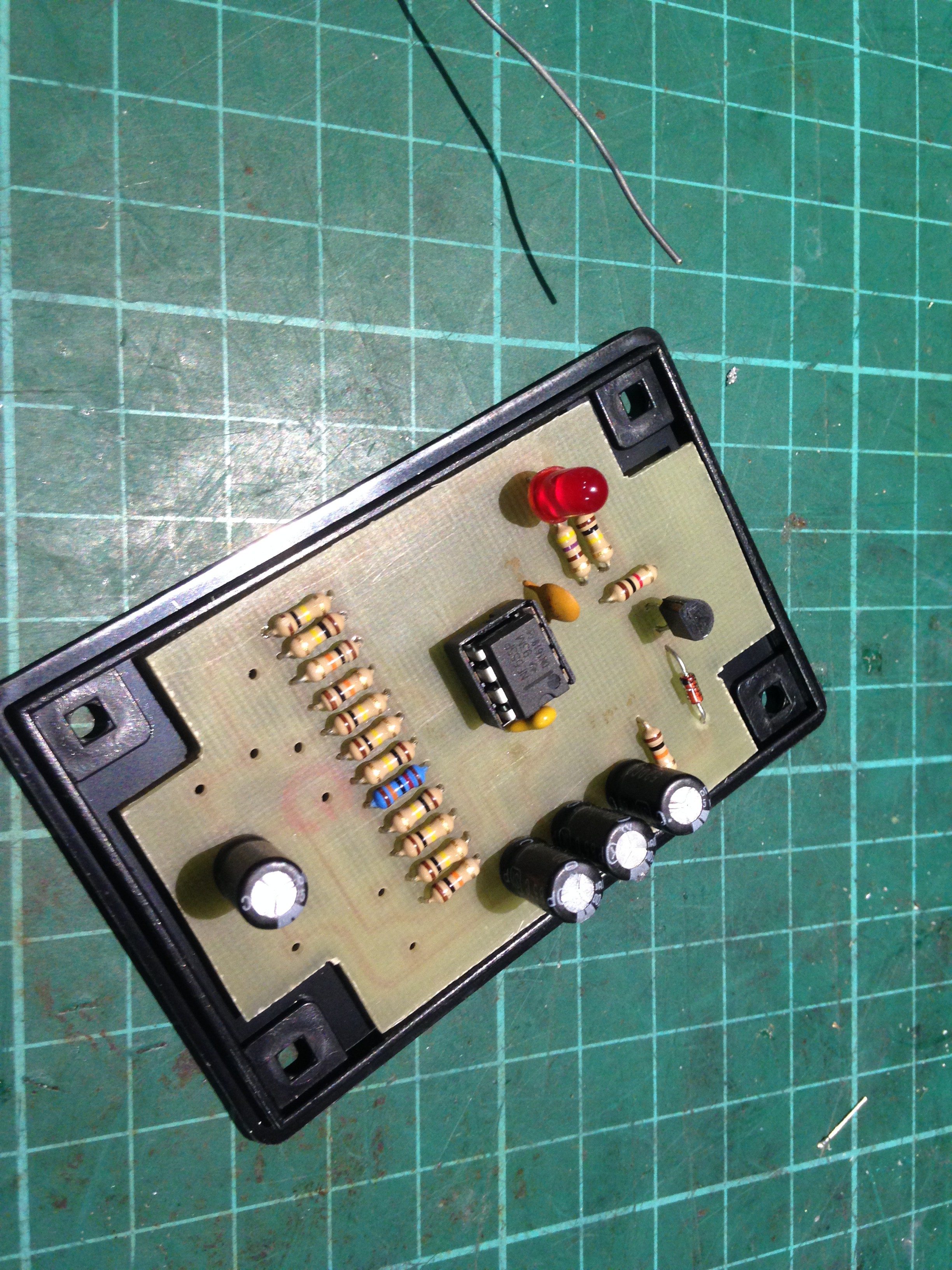
Its in the Box
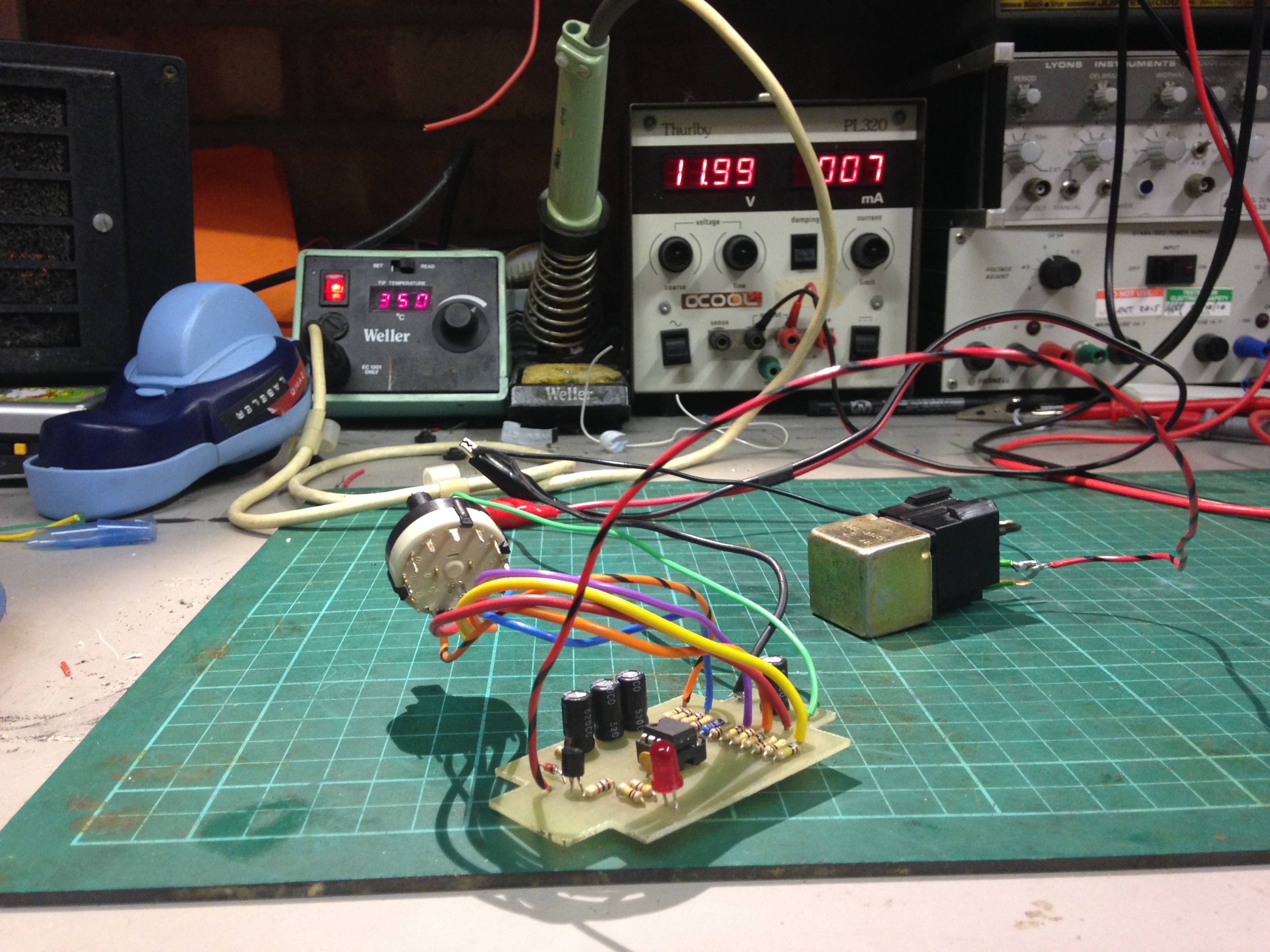
10/06/2017 at 12:12 • 0 commentsGetting back to it: I quickly tested my circuit with an actual automotive relay connected to it and it worked!
![]()
I decided that it was the time to get this in a box. Drill a hole in the side and fitted a grommet, unsoldered all the wires off the switch and relay, passed them through the hole and resoldered all the connections with heatshrink:
![]()
I glued the PCB to the lid of the box with some hot glue, which I don't know if it was a bad idea, but the alternative was Araldite, which would be more permanent. Then using a faston crimp terminal, removed the red plastic sleeving and inserted it into the pole terminal of the relay, making it change over configuration as required.
I could glue this contact in place as it doesn't have the tang to hold itself inside the relay holder like the other contacts, but its holding itself with its own retention well enough.
![]()
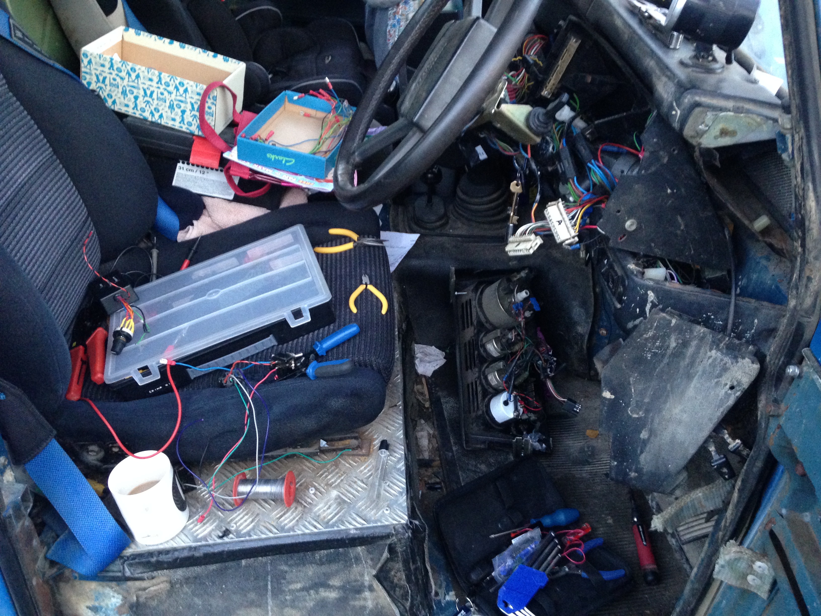
It is now ready to be installed behind my centre console in the landrover. A job for another day.
-
Post Summer Update
09/28/2017 at 08:35 • 0 commentsBeen on holiday. When I got back there was a huge amount to get done at work and home so not really had time to get this installed yet. Rest assured with impending winter weather, it will be installed!
-
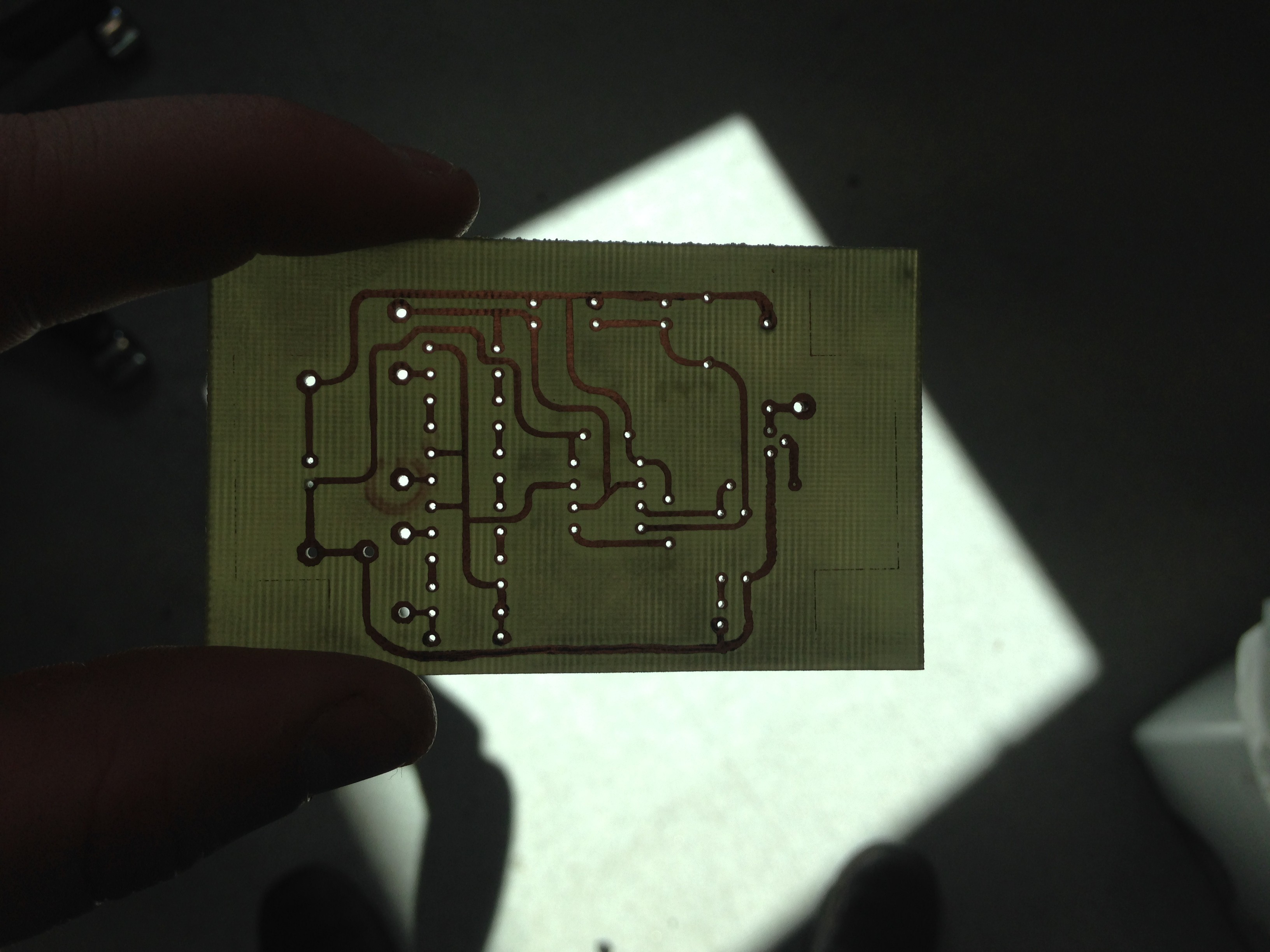
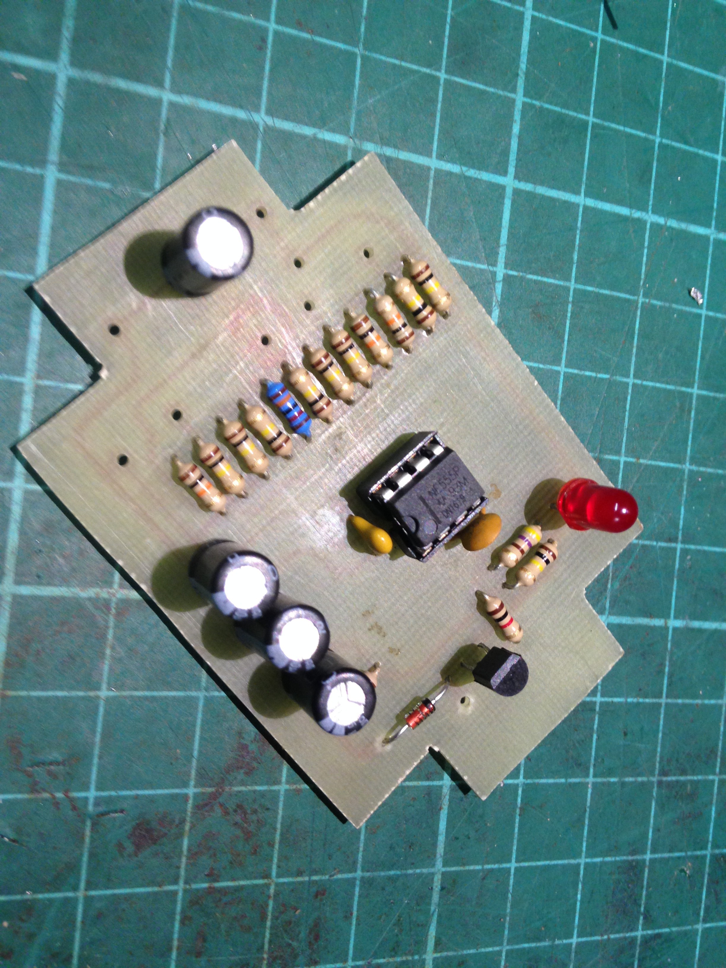
PCB Assembled
08/15/2017 at 21:37 • 0 commentsI managed to drill and assemble the PCB and even got round to doing a quick test:
![]()
![]()
![]()
![]()
a power on and jumping out so switch connections reviled all functions good, even the constant slow switch position.
-
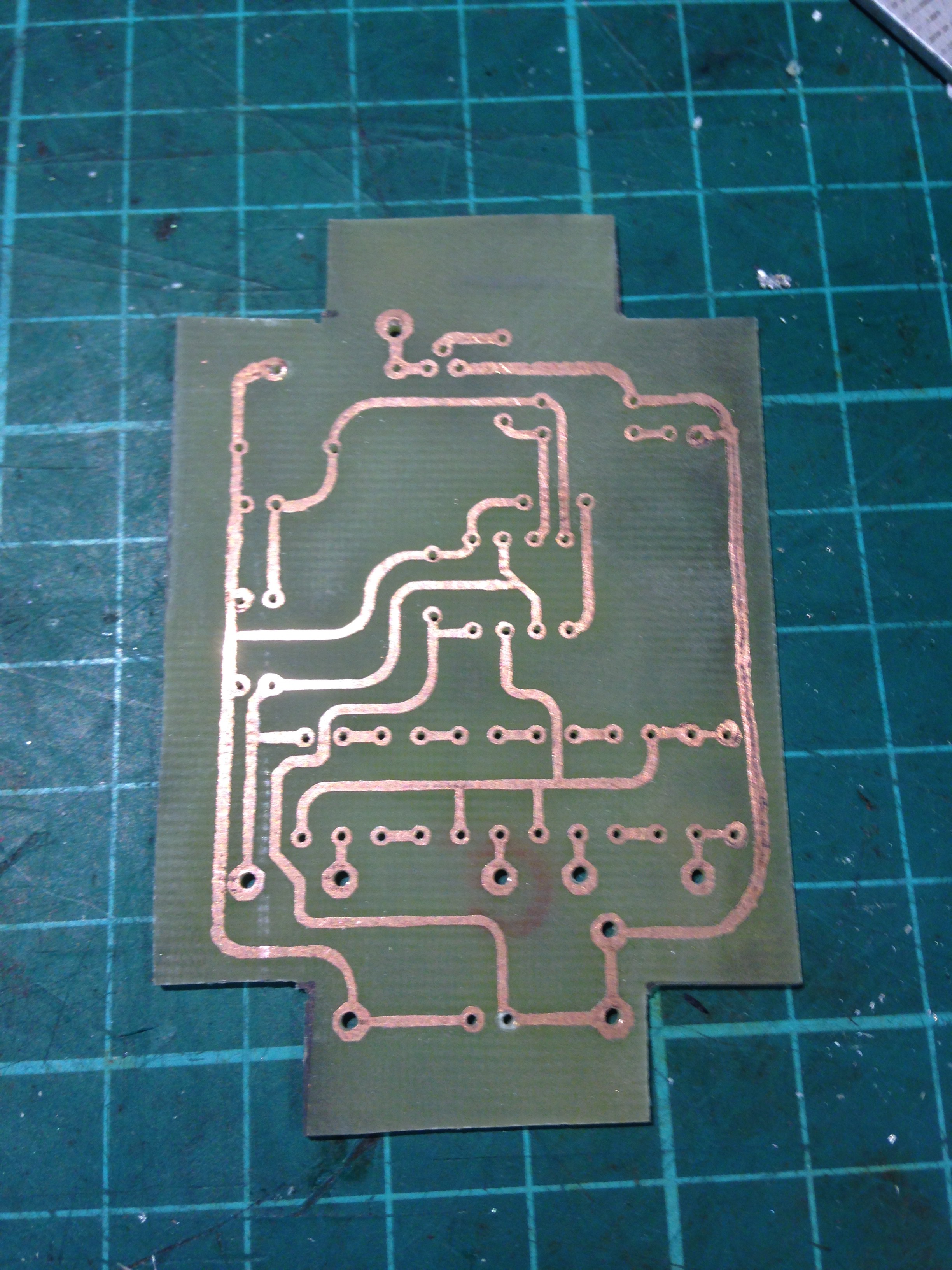
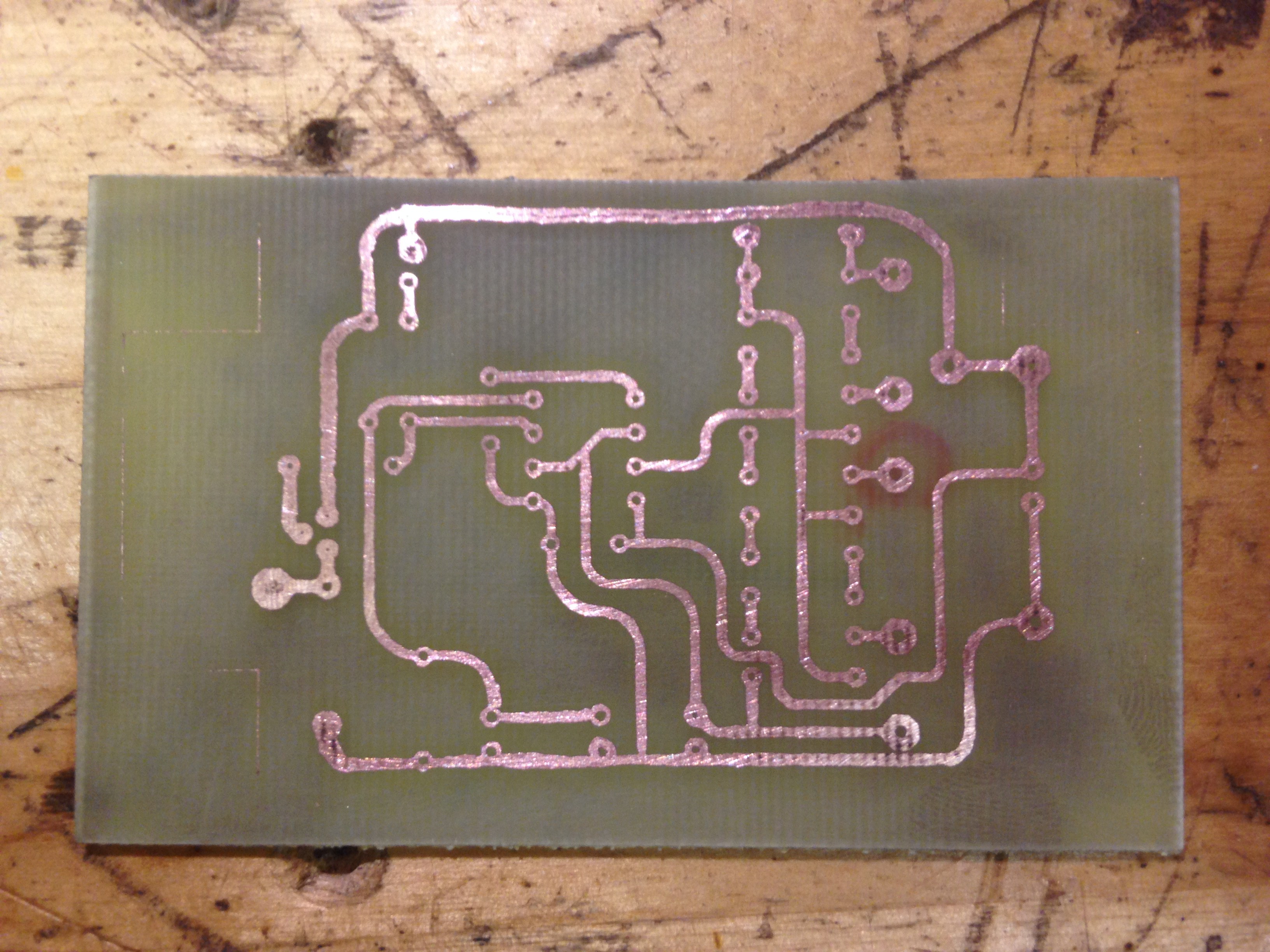
PCB #2 - A better outcome
08/06/2017 at 21:10 • 0 commentsSo I decided to have another go at etching another PCB. I found some bare PCB without photo resist and thought try again, but change my technique a little bit.
![]()
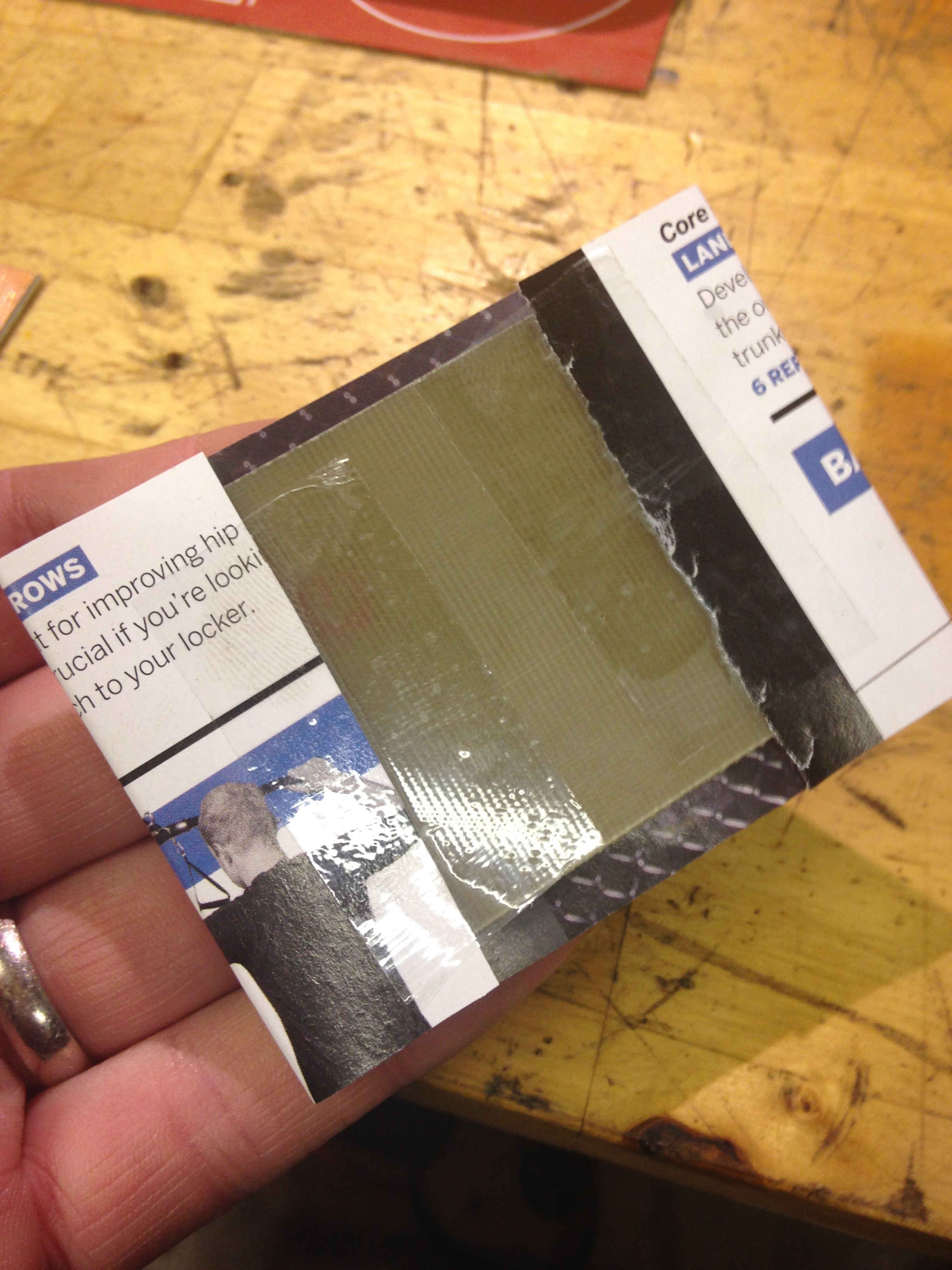
Firstly I rubbed up the copper first with some fine sand paper to 1) remove any oxide and contaminants and 2) hopefully roughen the surface to increase the chance of adhesion. I then taped down the transfer to the board using sticky tape - ideally you should use capton tape as I found when applying heat it shrinks, but so long as you don't leave it on so long it burns, its ok.
![]()
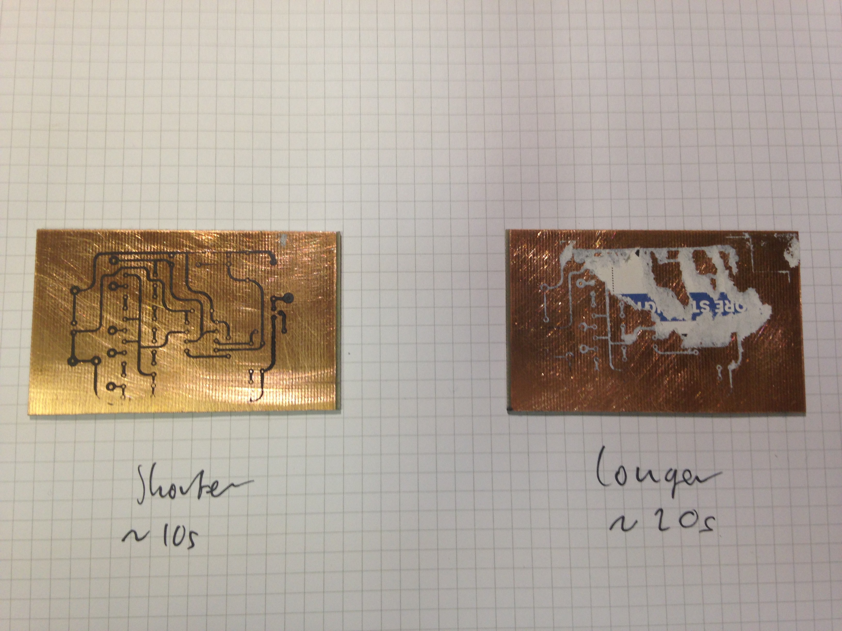
I also decreased the time I applied heat from the iron. As you can see being a bit quicker allowed the toner to transfer and not the magazine ink, which seems to stick too.
![]()
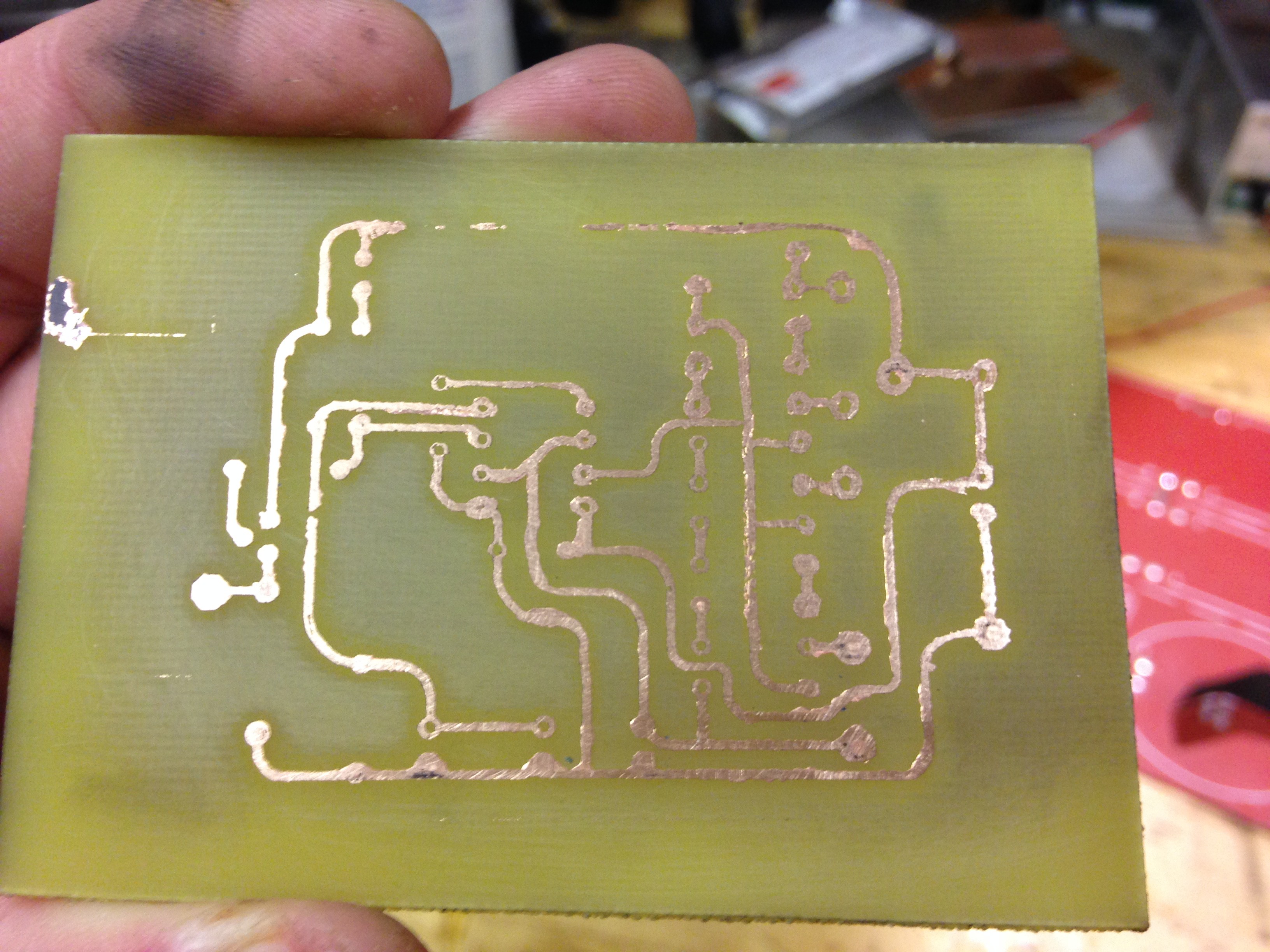
The transfer quality is much better than the last time, you can see the drill holes in the middle of the pads for a start! However it wasn't 100% perfect, and I still had to touch it up with a permanent marker.
After a FeCl bath and a rinse, here's how it came out:
![]()
A massive improvement from the last time! I'm going to drill this and trim it to the final dimensions and get this soldered up!
-
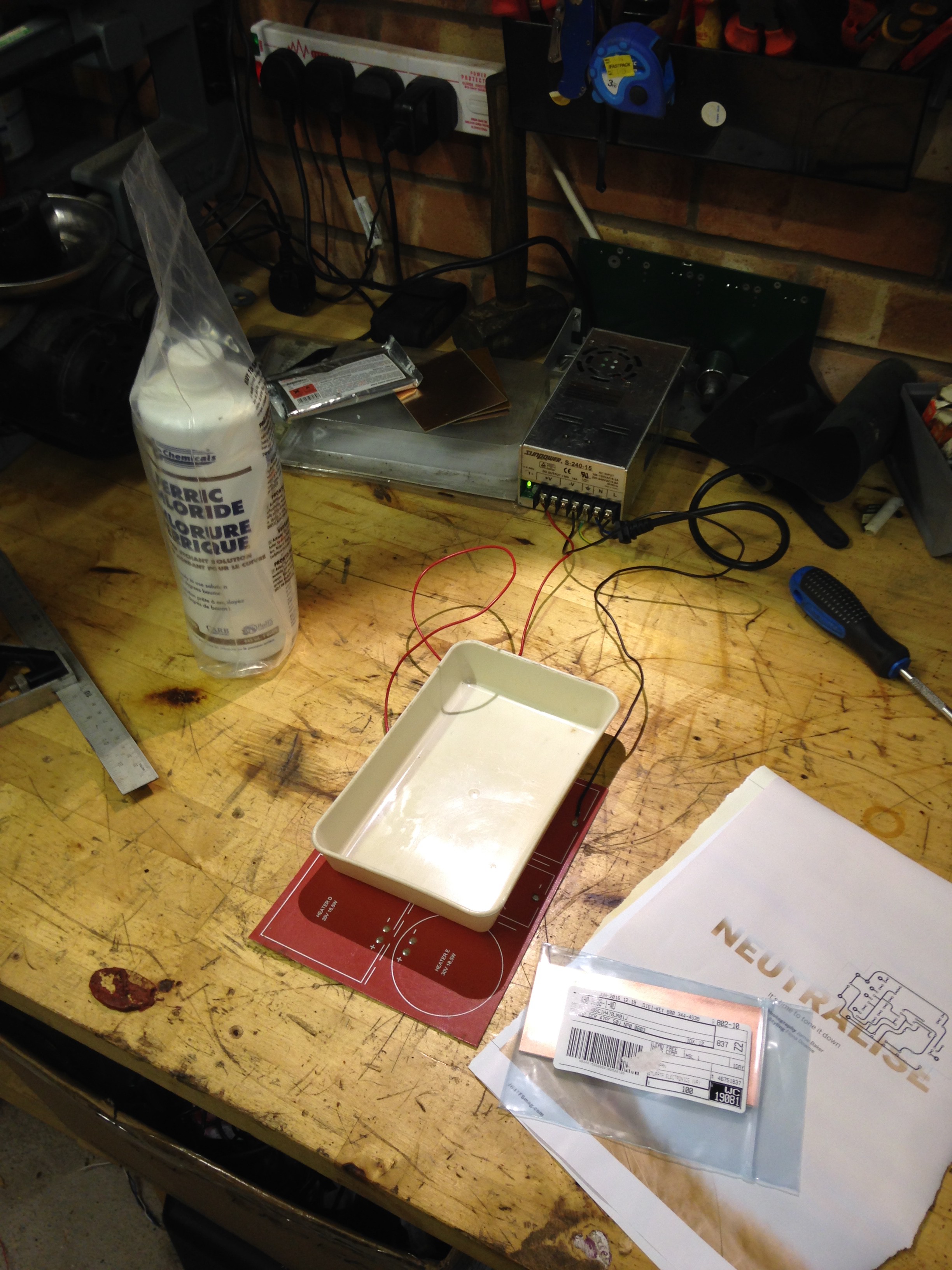
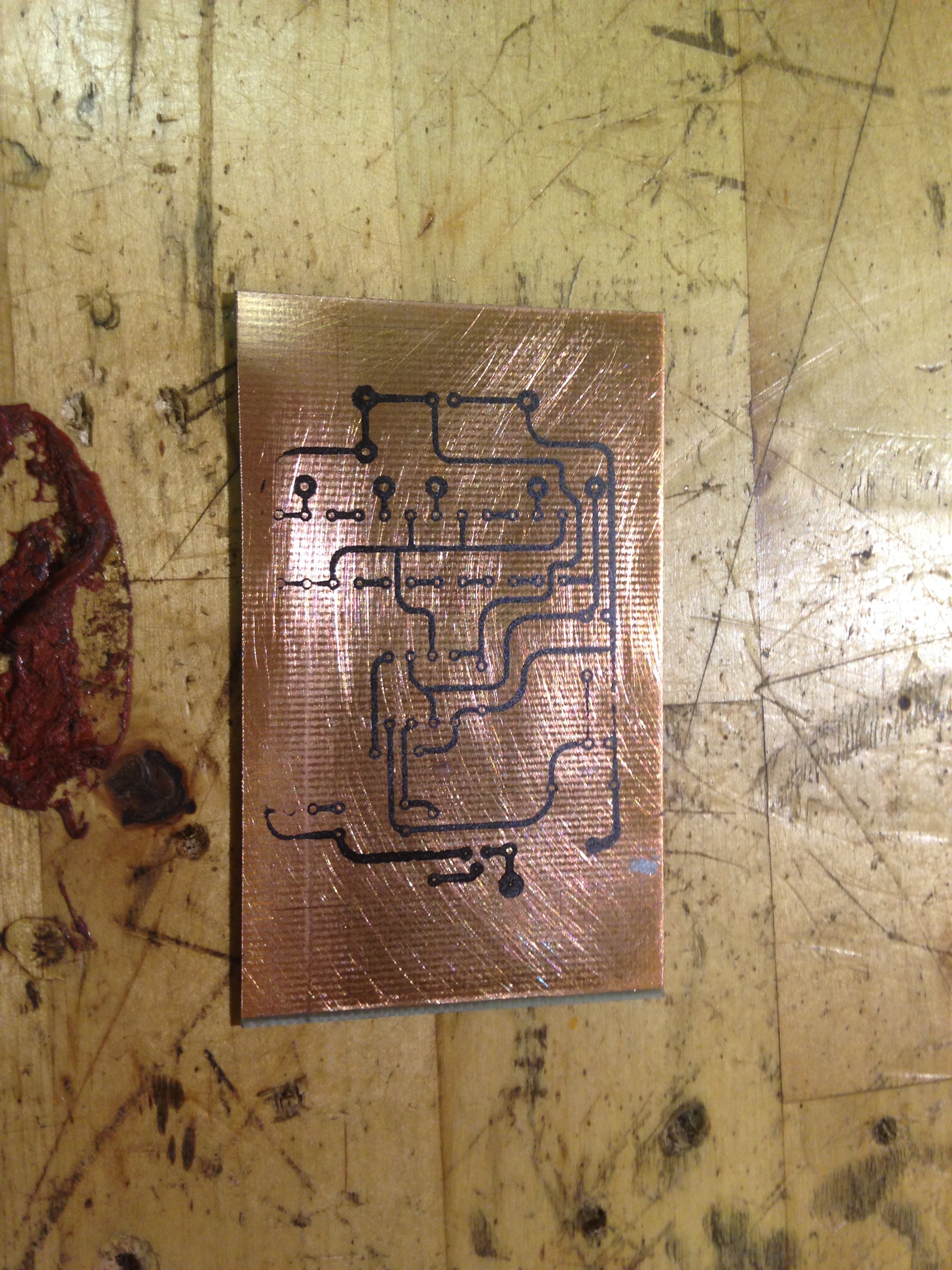
First PCB Etch
08/03/2017 at 12:22 • 0 commentsI Etched my First PCB at home using the toner transfer on magazine paper method using the PCB transfer I made in EAGLE (See files I've added):
![]() NOT TO SCALE - DO NOT COPY, BOTTOM SIDE AS VIEWED FROM TOP
NOT TO SCALE - DO NOT COPY, BOTTOM SIDE AS VIEWED FROM TOPI printed it off onto gloss magazine paper, cleaned the surface of the PCB, hooked up a heated pad to a power supply to warm the ferric cholride and aid to speed up the etching process...
![]()
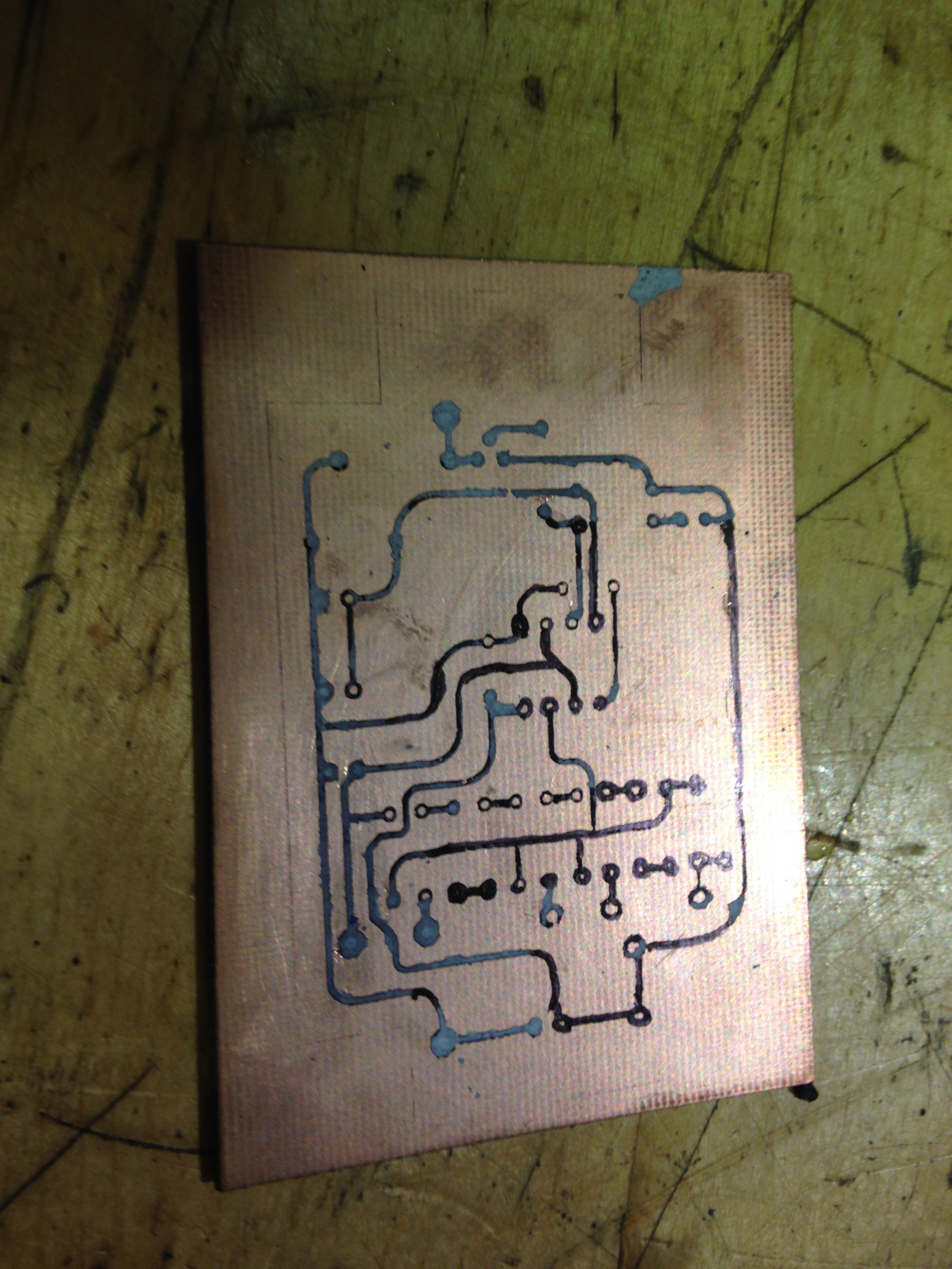
...then applied the transfer to the PCB using a clothes Iron with a sheet of foil between the paper and iron surface, Iron was cranked to highest setting and pressed down for about 5mins and after a bath in water, managed to peel off the magazine paper:
![]()
Some touch-up was required with the permanent fine marker and then into the etch bath. Here's how it came out...
![]()
Hmmm....not the best really, would work if i did a little fettling. I think the issue is I am leaving the iron on for too long and the toner is bringing the paper with it and also bleeding.
Unfortunately this was the only piece of bare copper clad I had, the others have photo-sensitive resists on them, If i can get hold of some transparency and leave it out on a sunny day then I could get the same result. I have some more bare copper coming soon.
I'm going to make another attempt either using the photo-resistive stuff or the bare clad when it arrives.
-
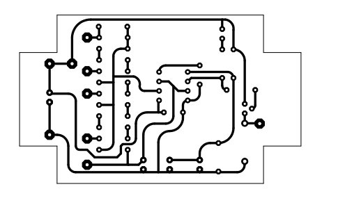
Schematic and board layout complete
07/30/2017 at 22:23 • 0 commentsSo I've done a quick schematic and done a board layout, which I have uploaded to my files for this project (see above).
I'll upload the trace transfer once I've verified it works and comes out OK from the etching process.
-
Some Purchases...
07/28/2017 at 21:16 • 0 commentsToday I went on Amazon and bought a pack of 10 single-sided copper clad boards, some ferric chloride and a toner cartridge for a laser printer I found in a recnet dumpster dive that worked.
My plan is to try out the toner transfer method of making my own PCB's and hope to make one for this project.
Time to dust free-eagle and get the PCB designed!
-
Additions to my interval circuit
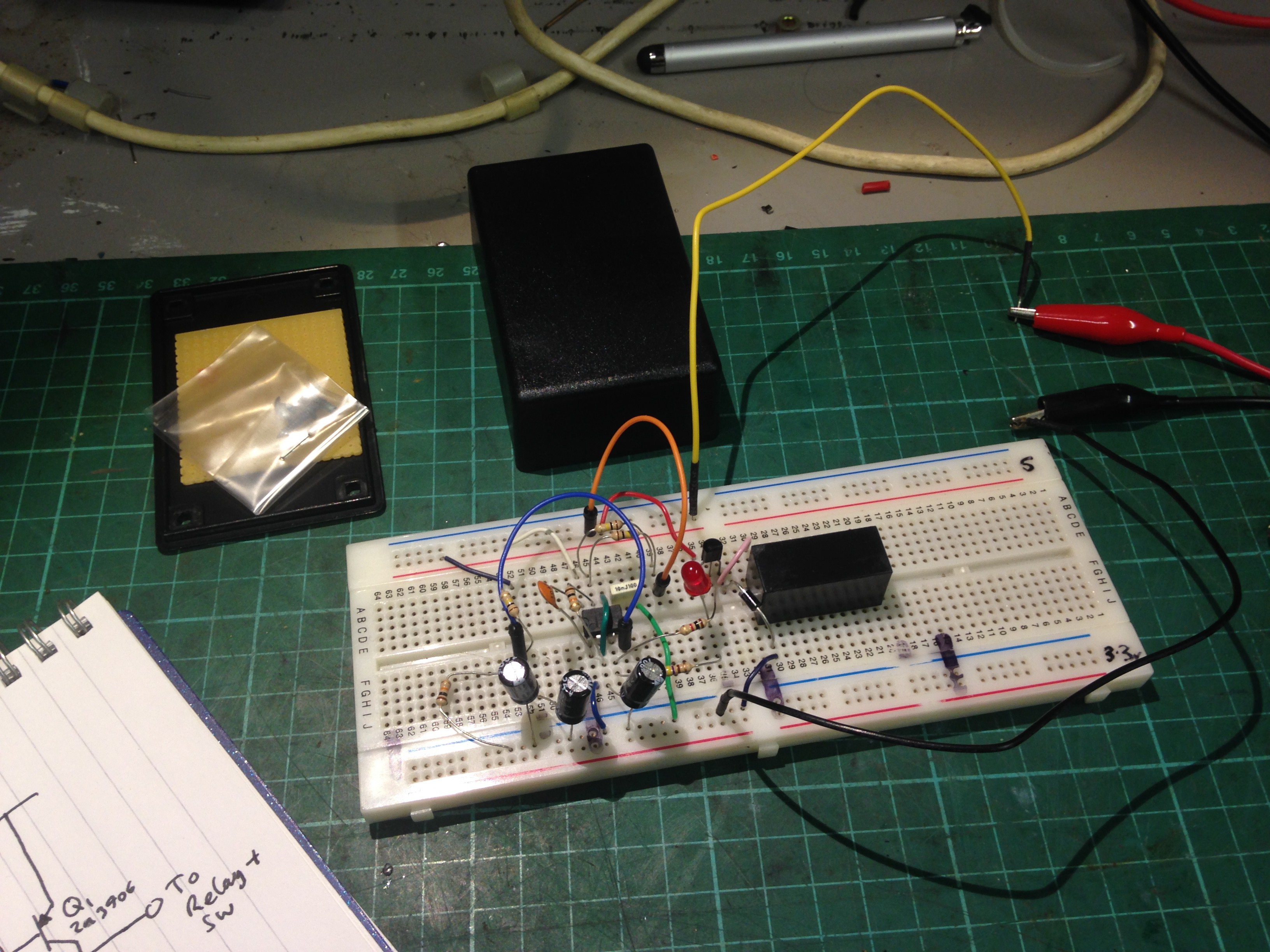
07/26/2017 at 20:19 • 0 commentsHad a quick tinker with this project last night.
![]()
With the new update for the wiring schematic meant that the output of my Interval circuit (see above).
The relay I'm controlling requires it to be driven by 12V instead of being pulled down to 0V.
Considering that the output of the timer is low for <1 second and high for the set interval, I need a PNP or P-channel MOSFET to drive the relay from the 555 timer output.
The chosen device to do this: 2n3906 - cheap, readily available, and up to the job.
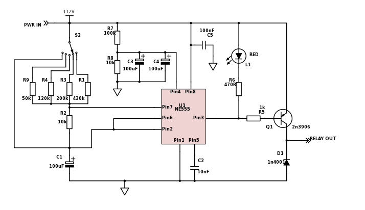
After bread-boarding up the circuit, I came up with this schematic:
![]()
It works well but there is a strange anomaly where upon first power up and the reset circuit (consisting of R7, R8, C3 & C4) forces the output low, there was a delay between the output of the 555 going low and the test relay I was using energising. After that it worked as expected.
As you can see I also connected one of the positions of the rotary switch (S2) directly to pins 2 & 6 of the 555 timer. This is instead of bypassing the 555 altogether and connecting power directly to the relay. The reason for this is that according to the 555 datasheet:
![]()
So with 12V at these pins, both conditions are satisfied and the output will be low constantly. However this will need testing first.
Landy Wiper Control
Sick of having 2 speeds for my windscreen wipers. Nothing a 555 timer can't fix!
 NOT TO SCALE - DO NOT COPY, BOTTOM SIDE AS VIEWED FROM TOP