Tron9000
-
MOT Passed! And Amendment
07/14/2017 at 11:17 • 0 comments...there's a relief!
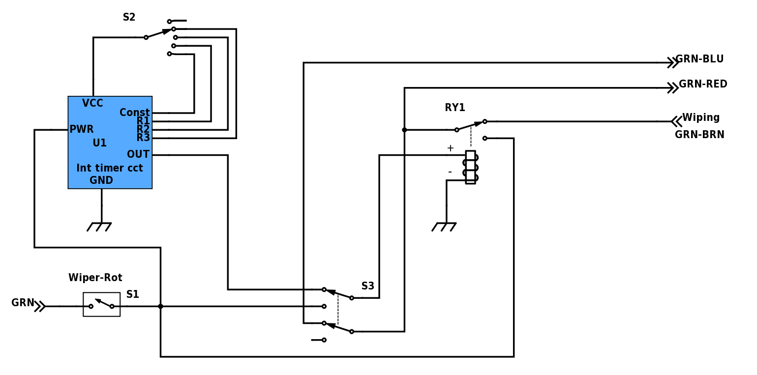
I also decided to alter the wiring for how the timer box will be fitted into the existing system:
![]()
I also Updated the project description for how this operates. (see description section above).this design more simple and easier to to install.
-
Impending MOT
07/11/2017 at 20:32 • 0 commentsWith an MOT looming I thought I'd best just get everything in order before the test as no windscreen wipers are an MOT failure
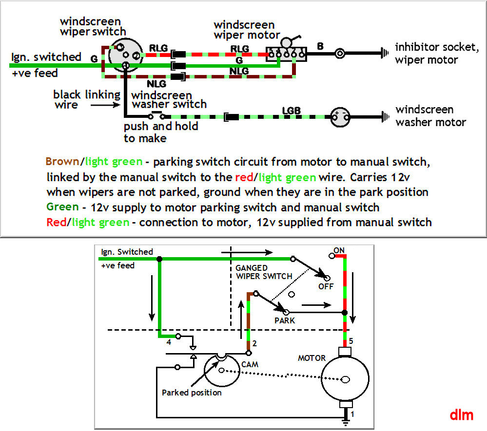
Whilst trying to wire it up I was a bit confused as to what the point of the Brown-Green Wire was. I know it stayed at 12V whilst the wiper was in motion, but then where does this signal fit in?
The wiring diagram for the vehicle didn't do much good, as it just shows the wiper switch as a unit and no internal details.
After a quick Google it became apparent: its a parking switch line that powers the wipers after you have switched them off till they are in the "parked" position, usually out of the way of the drivers view.
![]()
The Cam simply closes another switch and stays closed till the motor is back in the starting position. So if the wipers are turned off mid wipe, they will always return. When the wiper motor is parked it is also shorted, as not to move whilst the vehicle is moving.
So with the single pole double position rotary switch I fitted, I simply connect the pole to the motor and the brown and green wire to one position and the green wire to the other.
So with this in mind I was able to move the wipers controls from the steering column and to the centre console.
Fingers crossed for the MOT...
-
Fault Cleared and incorrect Colour Coding!
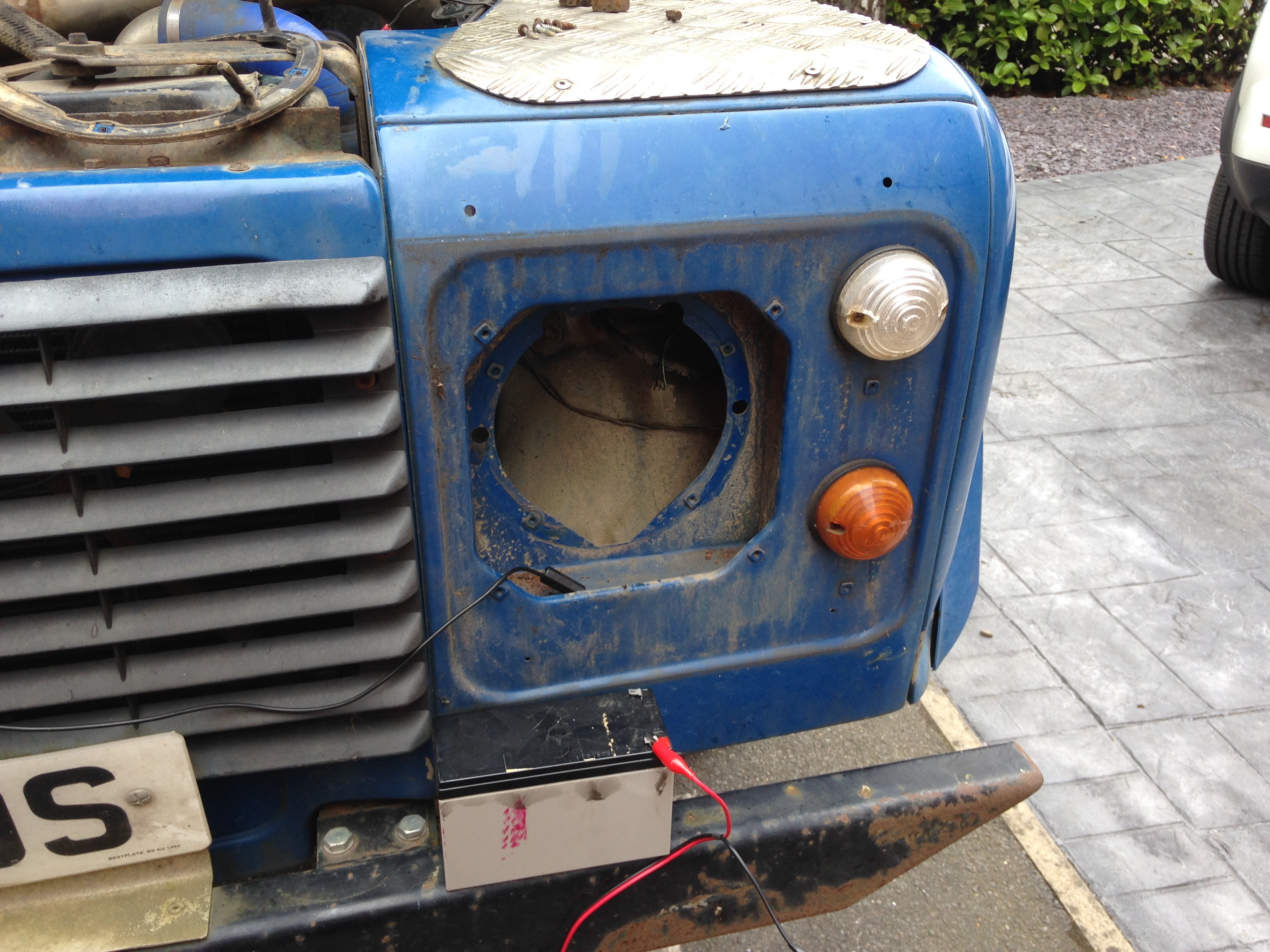
06/20/2017 at 14:22 • 0 comments![]()
So finding suitable access to the screen wash motor through the passenger side headlight, I was able to test it. But looking inside I found there were 2 pump motors, most likely one was for the rear screen wash when this vehicle hadn't had its back end shortened!
![]()
I test them by applying voltage from a 12V battery to the correct pins and they both worked!
However with power applied to the vehicle, it didn't which meant there was a break in the wires between switch and motor.
Now I was still under the assumption that the power was fed through the motor by the stork switch pulling one side to GND, as the wire on the stork metal case was black. After much fruitless continuity checking for a 12V feed to the motor connectors, I found a wiring diagram online and found that the washer motor was tied to GND meaning it was fed +12V!
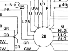
![]()
where 28 is the stork switch cluster and 25 is the wash motor (no the wire LGB does not mean its Lesbian Gay or Bi-sexual! It Means Light Green & Black). Upon closer inspection of the switch cluster I found this:
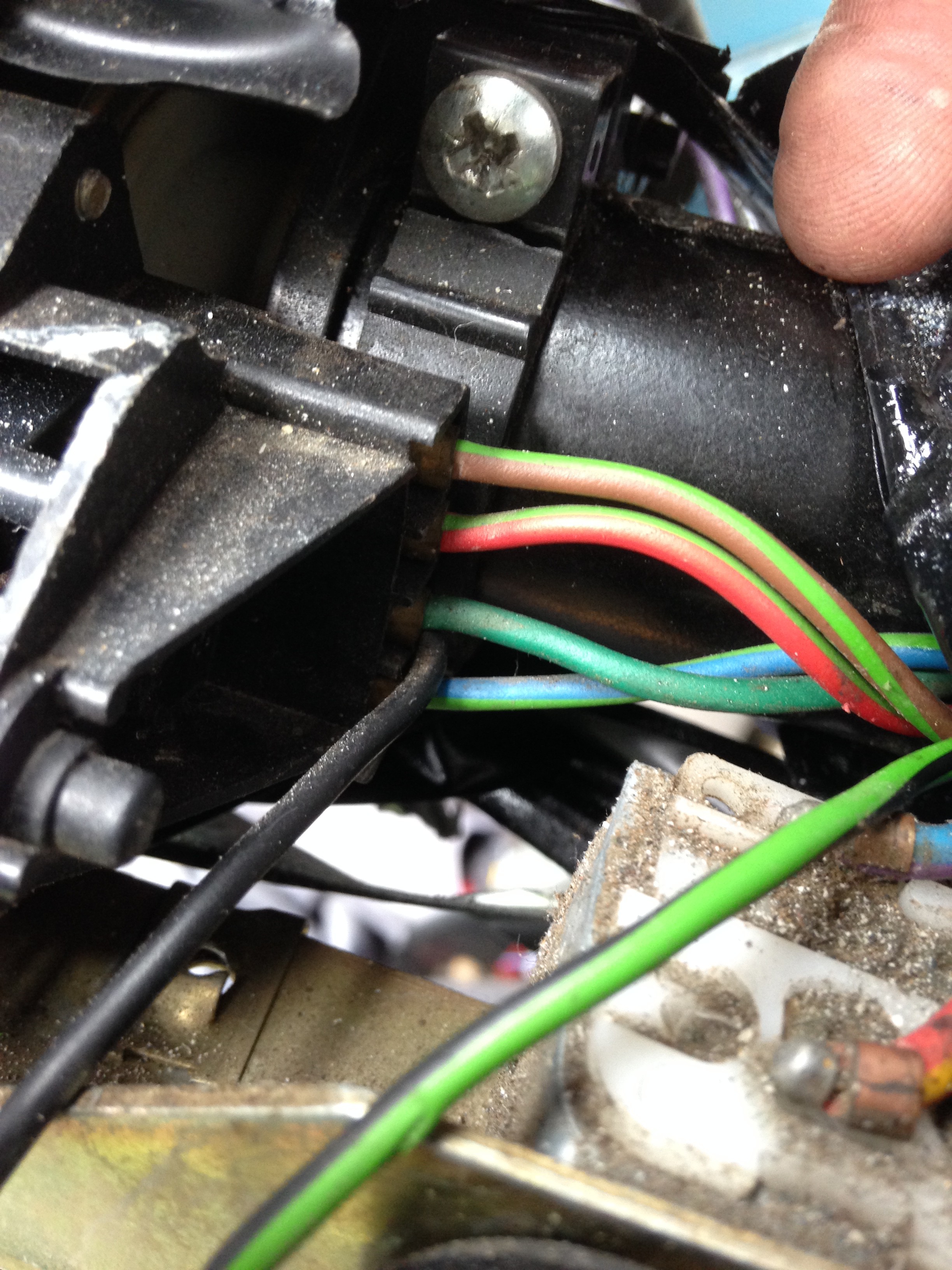
![]()
YEP! The Black wire which is usually universal for GND is actually connected to the Green wire which is the feed for all ancillaries! FML! Cheers Landrover! Hell some bloody green insulation tape would have been a least somewhat of a designation!
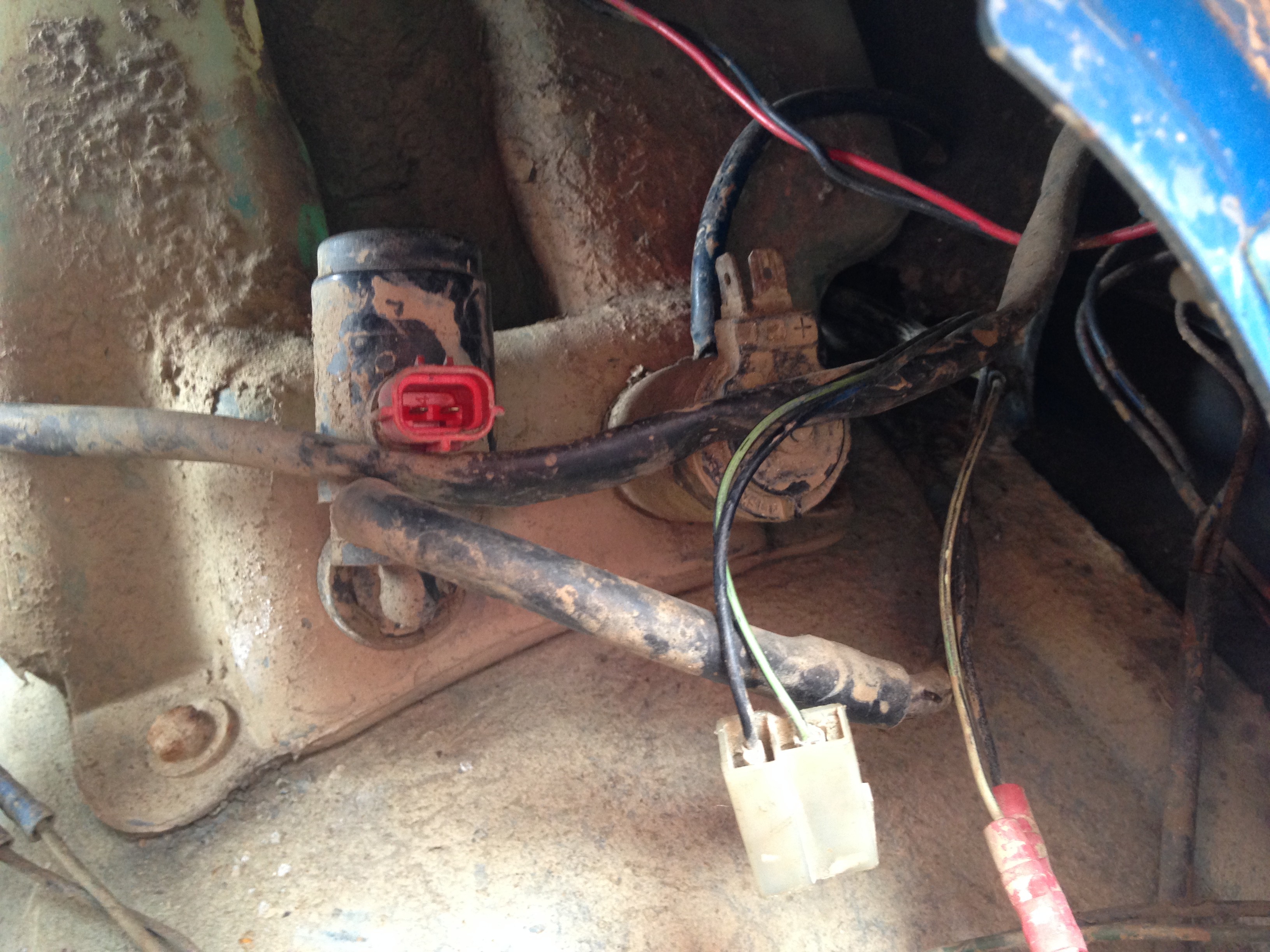
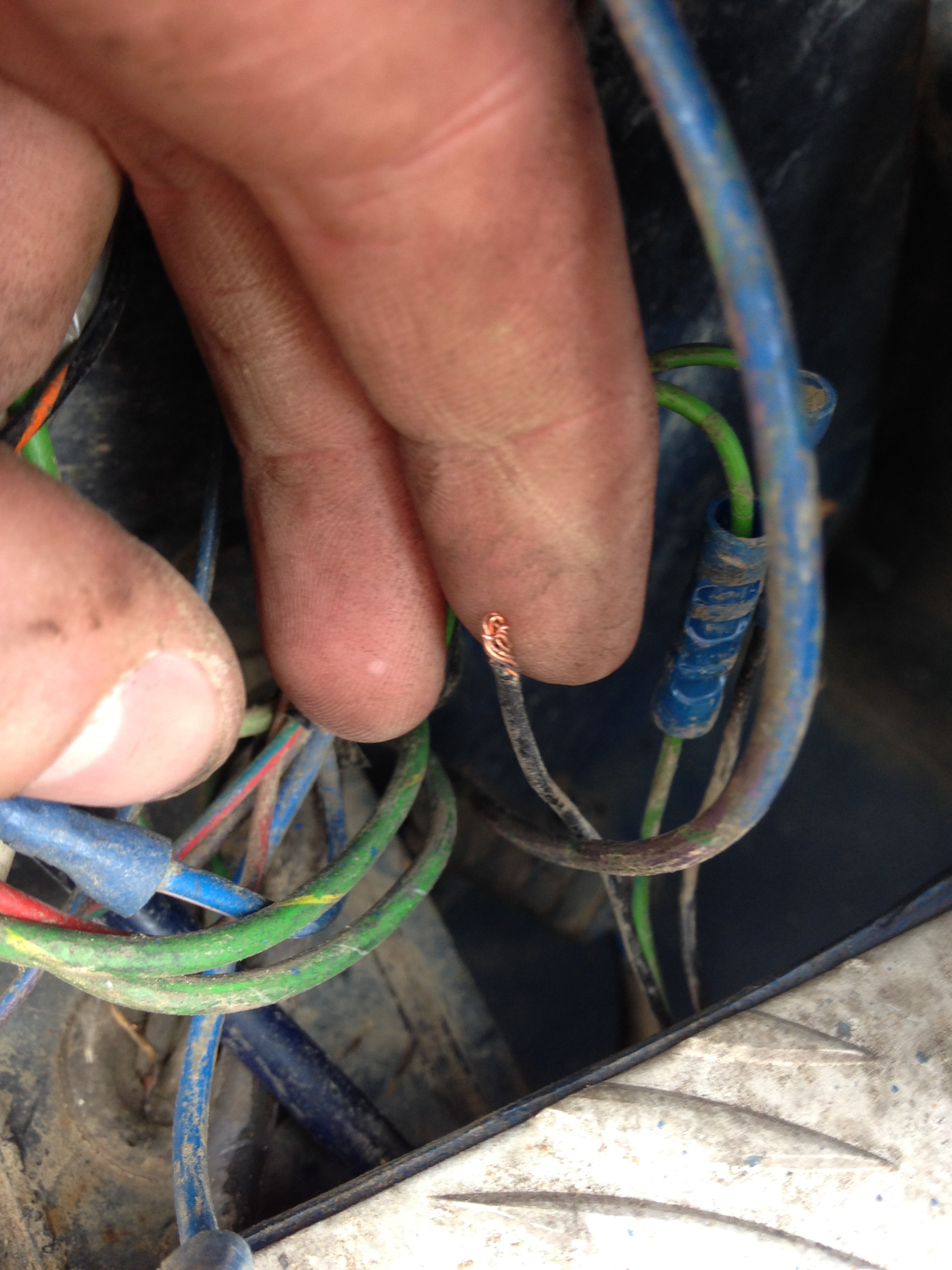
This meant that I could then correctly determine where my fault was now I knew what was going where, and low and behold, I found the culprit: a wire that had left its crimp, probably fitted by the previous owner, it was buried in insulation tape, no doubt to keep the weather out:
![]()
Fresh crimp and a quick check that the wash motor was working, and all was fixed! I am still confused as to how me hooking up the harness caused a wire to disconnect itself from a dodgy crimp!
Anyway at least now I can proceed. My new plan is to wire the switches from the stork cluster to the centre console and then fit in my 555 circuit.
-
Testing Harness
05/27/2017 at 20:34 • 0 comments![]()
Went and tested the harness and a number of issues and faults
- Had wrong connectors on end of harness to mate with connector
- Blew fuse for washer pump. Replaced fuse and tested pump again by shorting GRN-Blk to GND and not working so washer pump is probably FUBAR'd - fantastic... then realised I was driving the pump with 12V instead of pulling it down. Bellend!
- Tried the wiper functions and did not get any satisfactory results and blew a fuse for the wiper motor in the process.
So in summary I need to go back to the drawing board, give me head a shake, and try again!
-
Test Harness construction
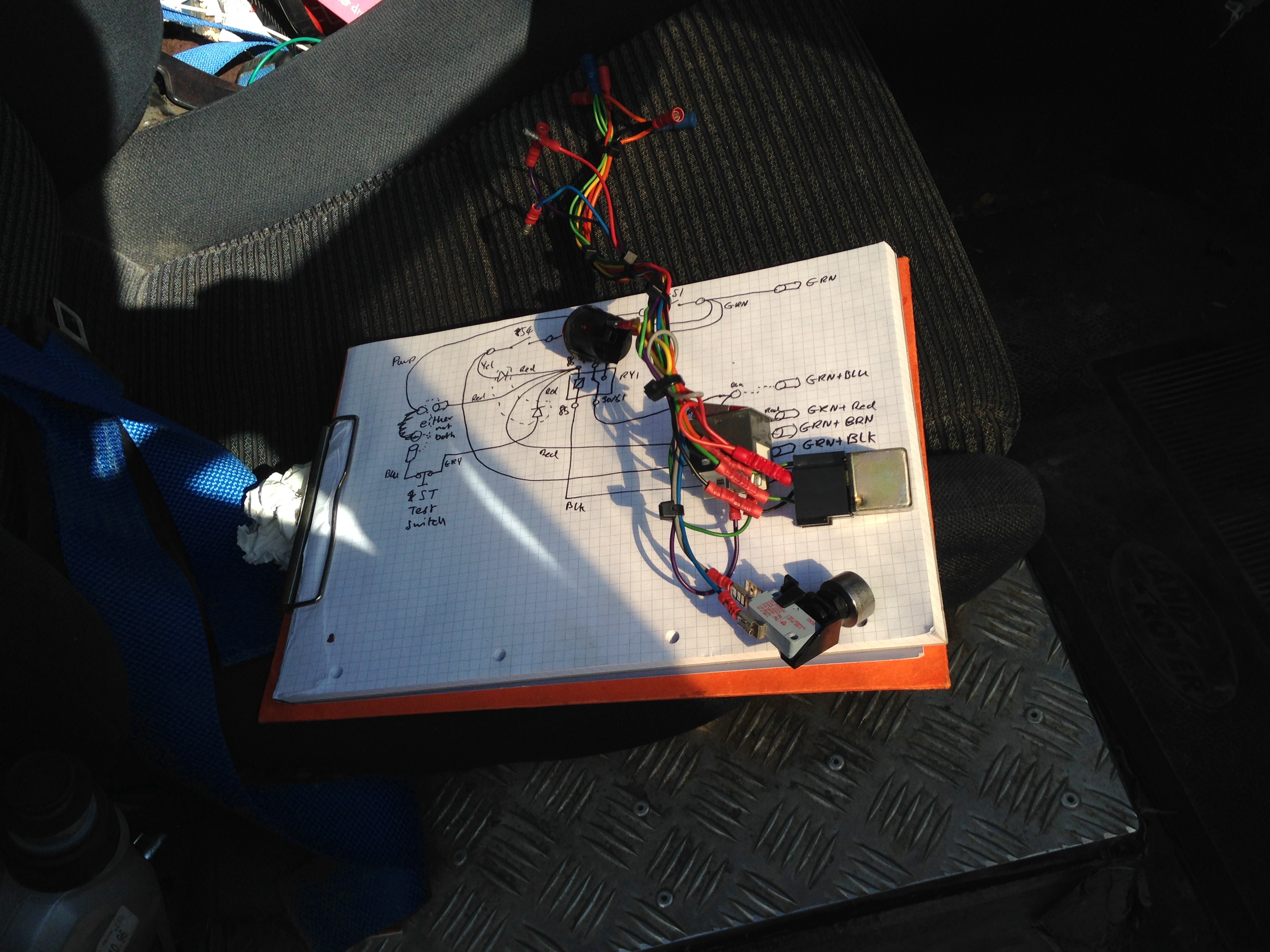
05/24/2017 at 20:12 • 0 commentsThis evening I assembled the test harness to confirm that my proposed harness design works.
First a quick sketch:
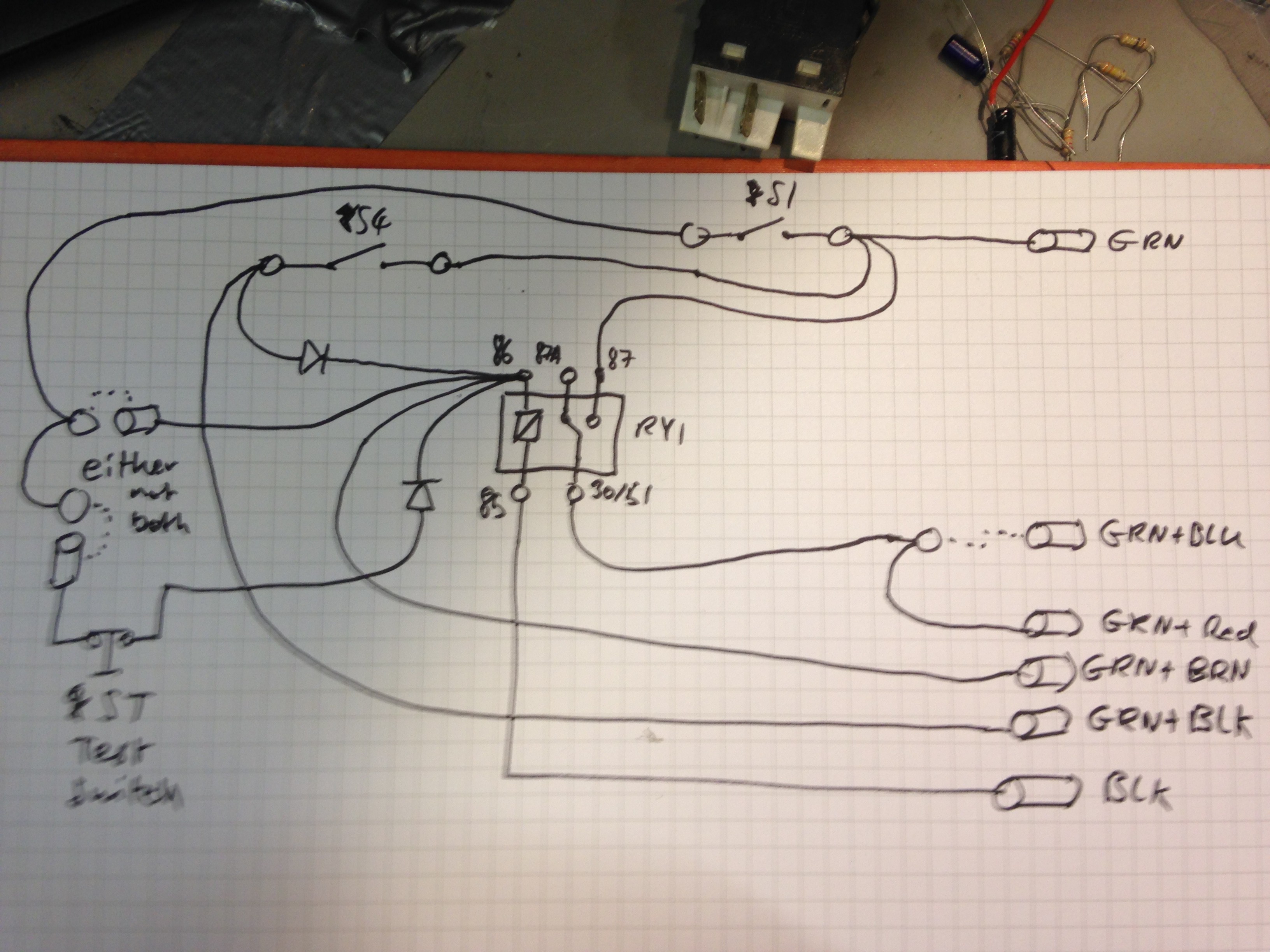
![]()
This is not representative of the final harness, ongoing improvements during construction. For example the 2 diodes: I decided to use a twin diode in a TO-220 package I salvaged from a PC SMPSU. The Test switch will basically a manual input from myself that will mimic the 555 timer interval box, and when the circuit is constructed, the switch can be removed and replaced with the circuit, as I designed it with crimp faston fittings.
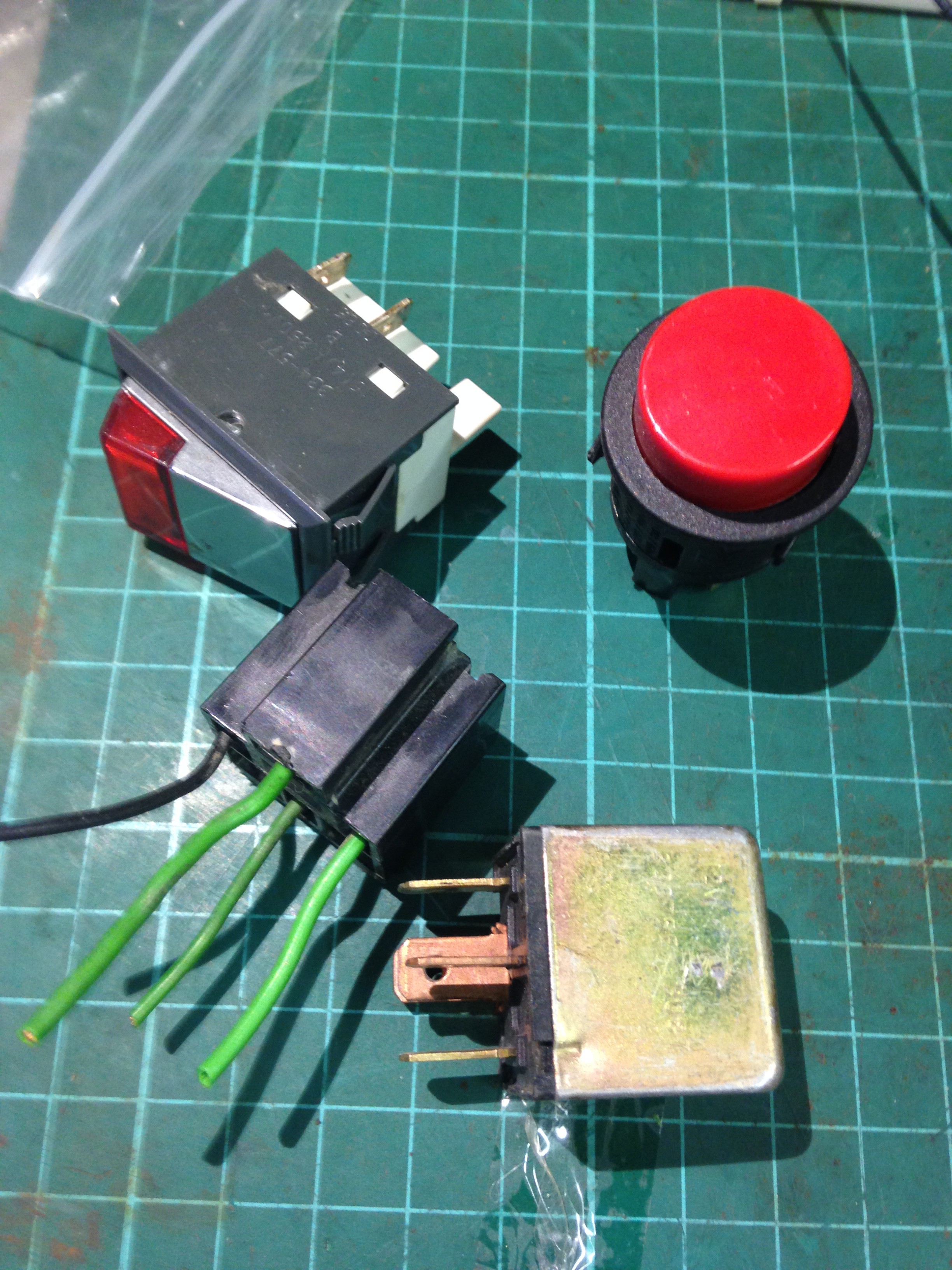
I then sourced some more switches and an automotive relay:
![]()
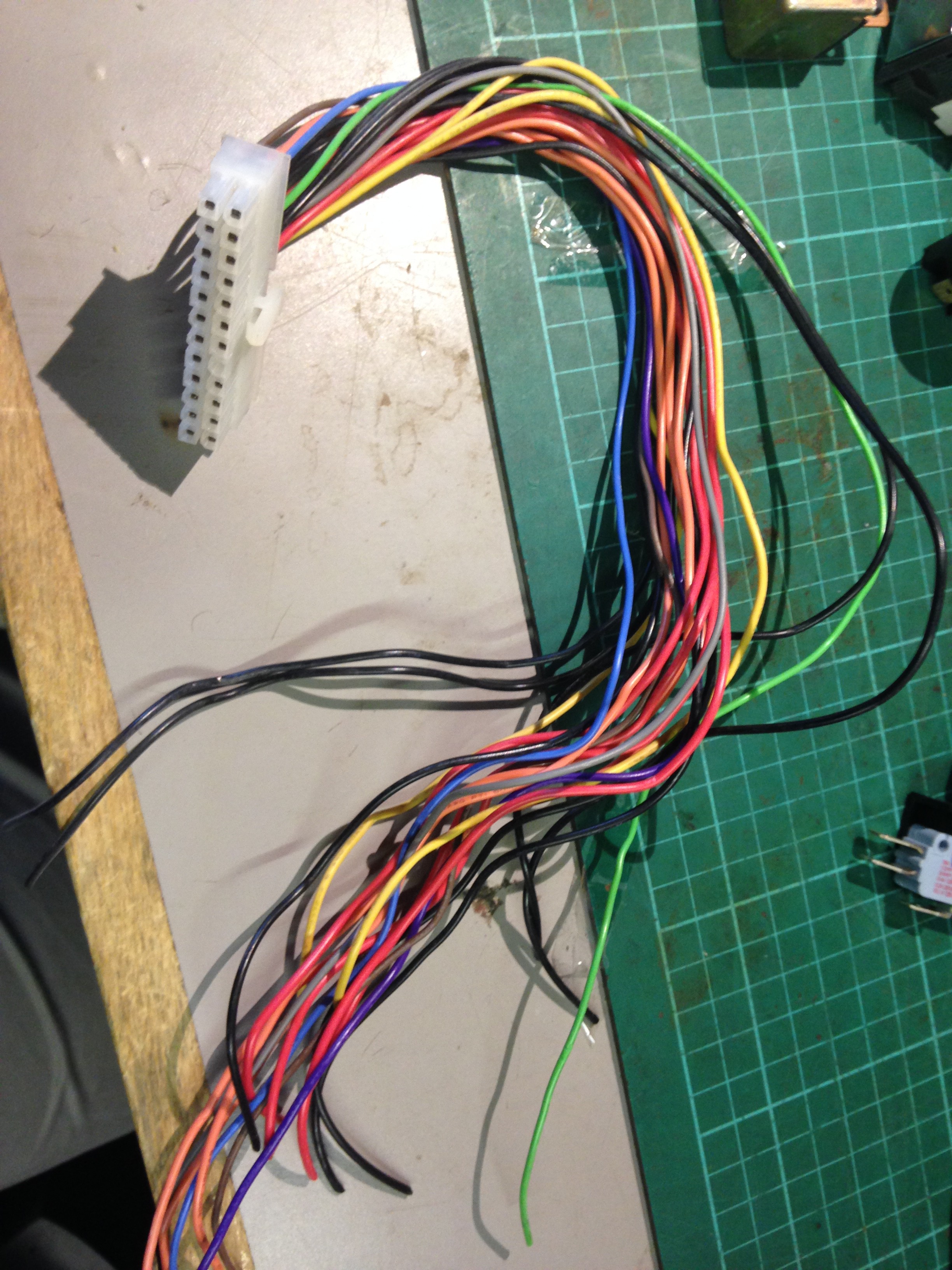
and sourced some wire:
![]()
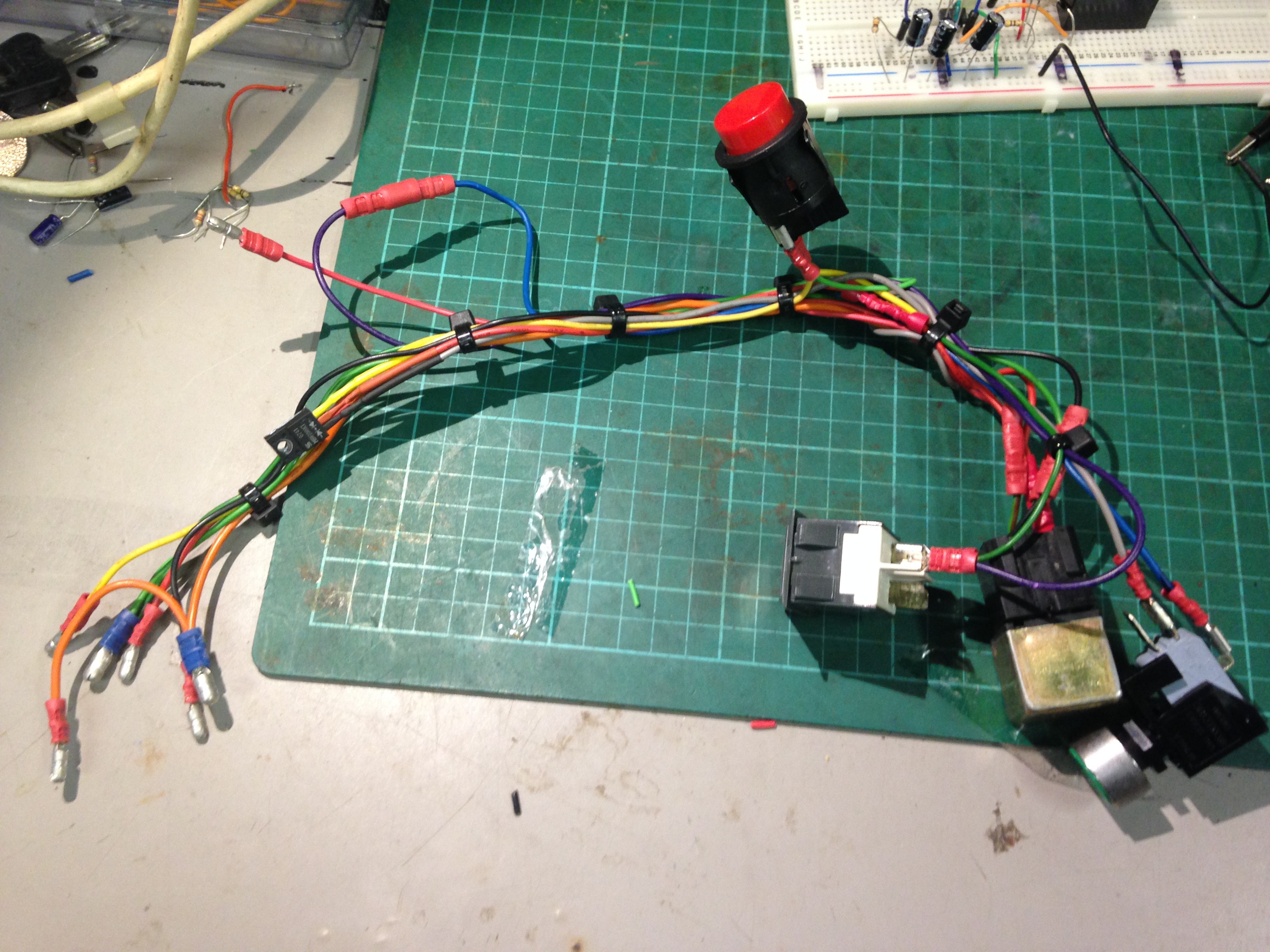
Pro-tip: ATX power supplies are a good source of decent gauge wire. So after about an hour of stripping wire and crimping connectors the harness was complete:
![]()
I'll be testing it by pluging it into the wiper socket on the landrover harness later.
-
Circuit Improvements
05/22/2017 at 21:11 • 0 comments![]()
This evening I have been developing the circuit so that the relay turns on when the circuit is first turned on. Before when the circuit was first energised, there was an approximately on RC delay between first turn on and first time the relay is energised.
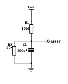
I really would like the relay to come on for about 1 second immediately upon turn on. To do this I decided to use an RC circuit on the reset pin of the 555 timer. The reset pin when pulled low, sets the output low. If this pins goes above 0.7V then the reset pin will release the output pin and astable operation will continue. I constructed the circuit below.
![]()
![]()
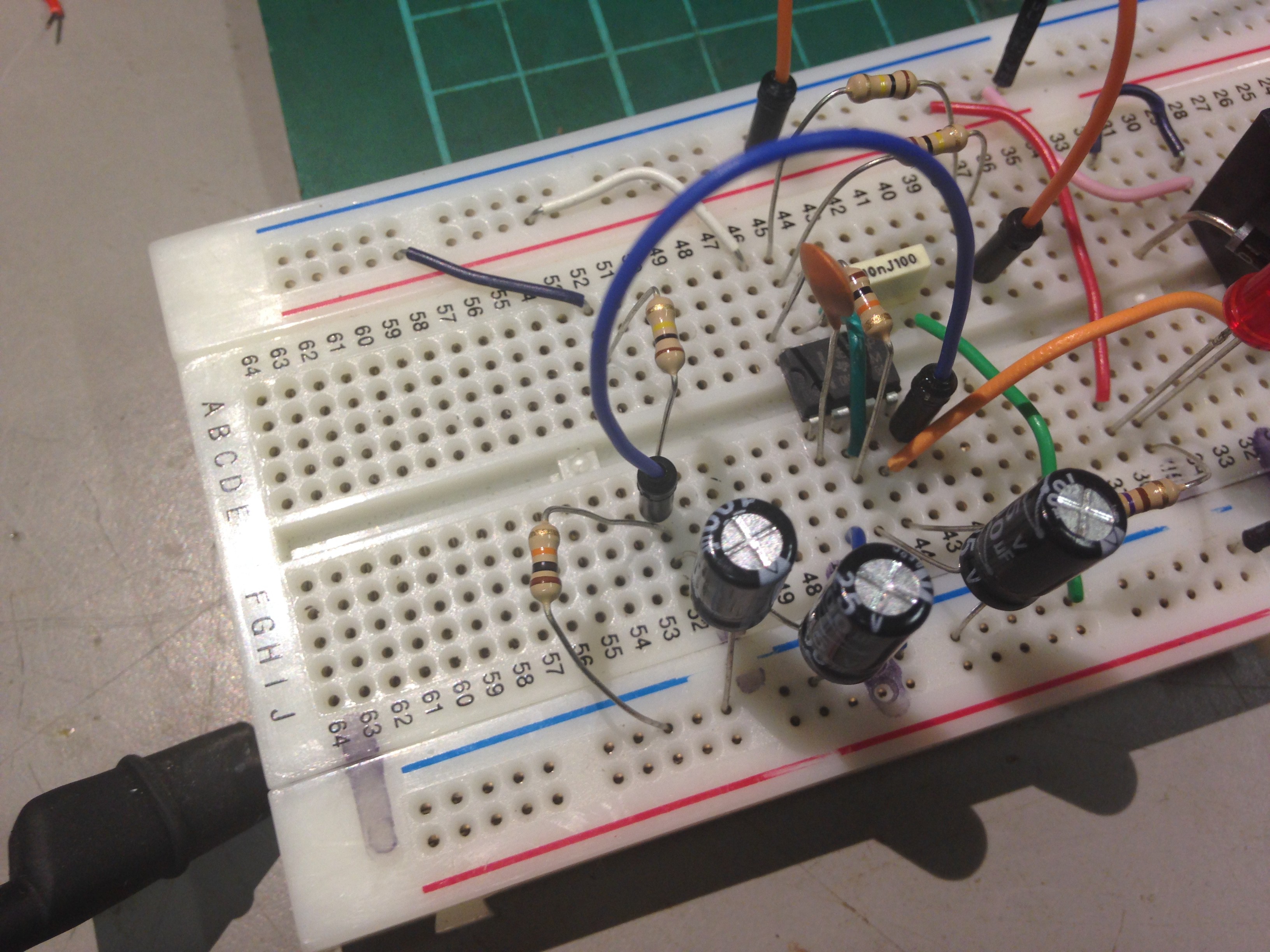
R1 and C1 for the RC network. To be honest, I didn't calculate the values, I picked some rough values. C2 is 2x 100uF in parallel. R2 is a bleed resistor, so that when the circuit is turned off, C2 discharge quick enough, should I change my mind.
I tested the charge time:
![]()
Took about 1 second to reach 0.7V.
I then tested it fully with 555 and it worked, the relay turned on as soon as the power was applied for about 1 second.
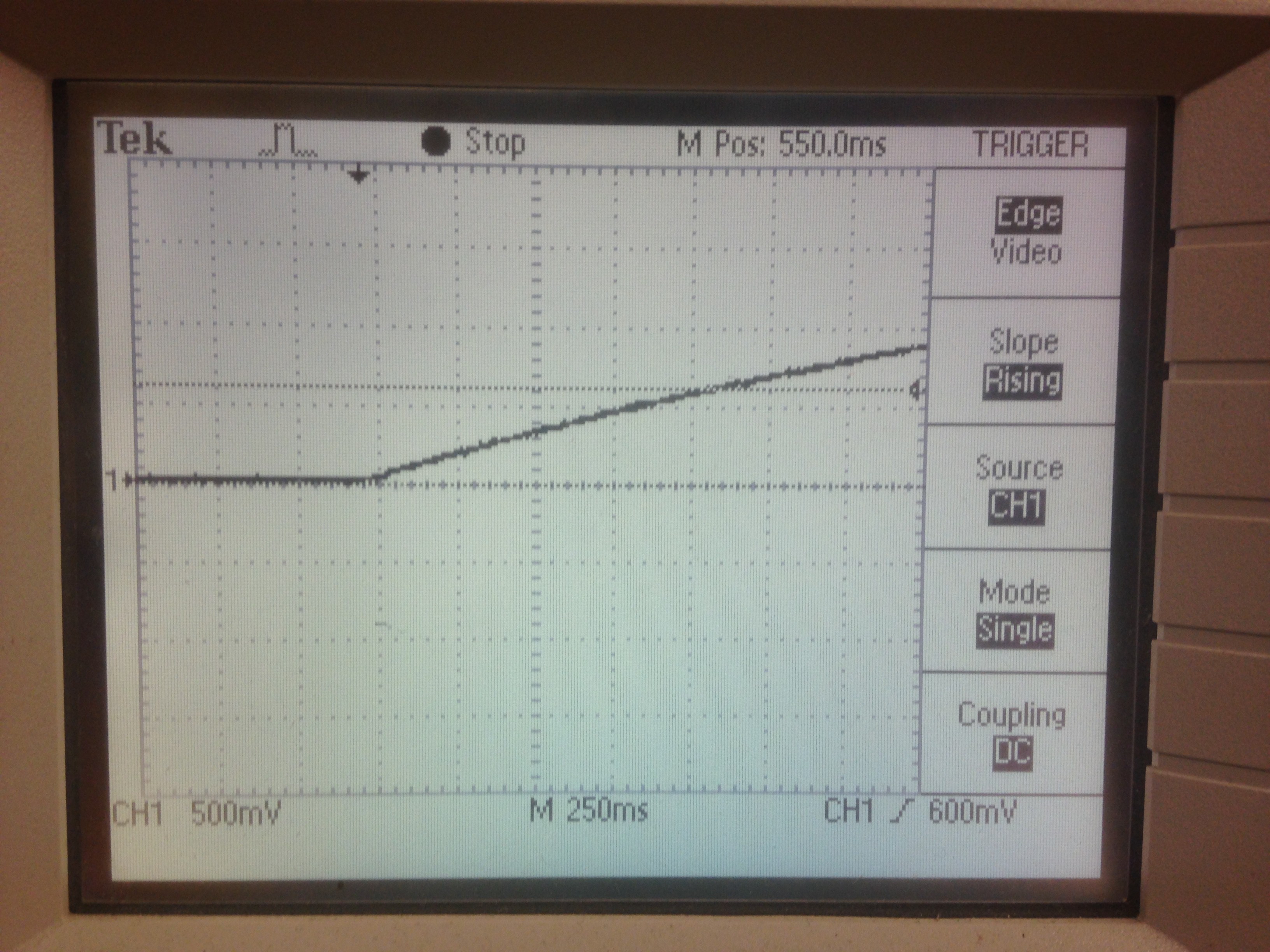
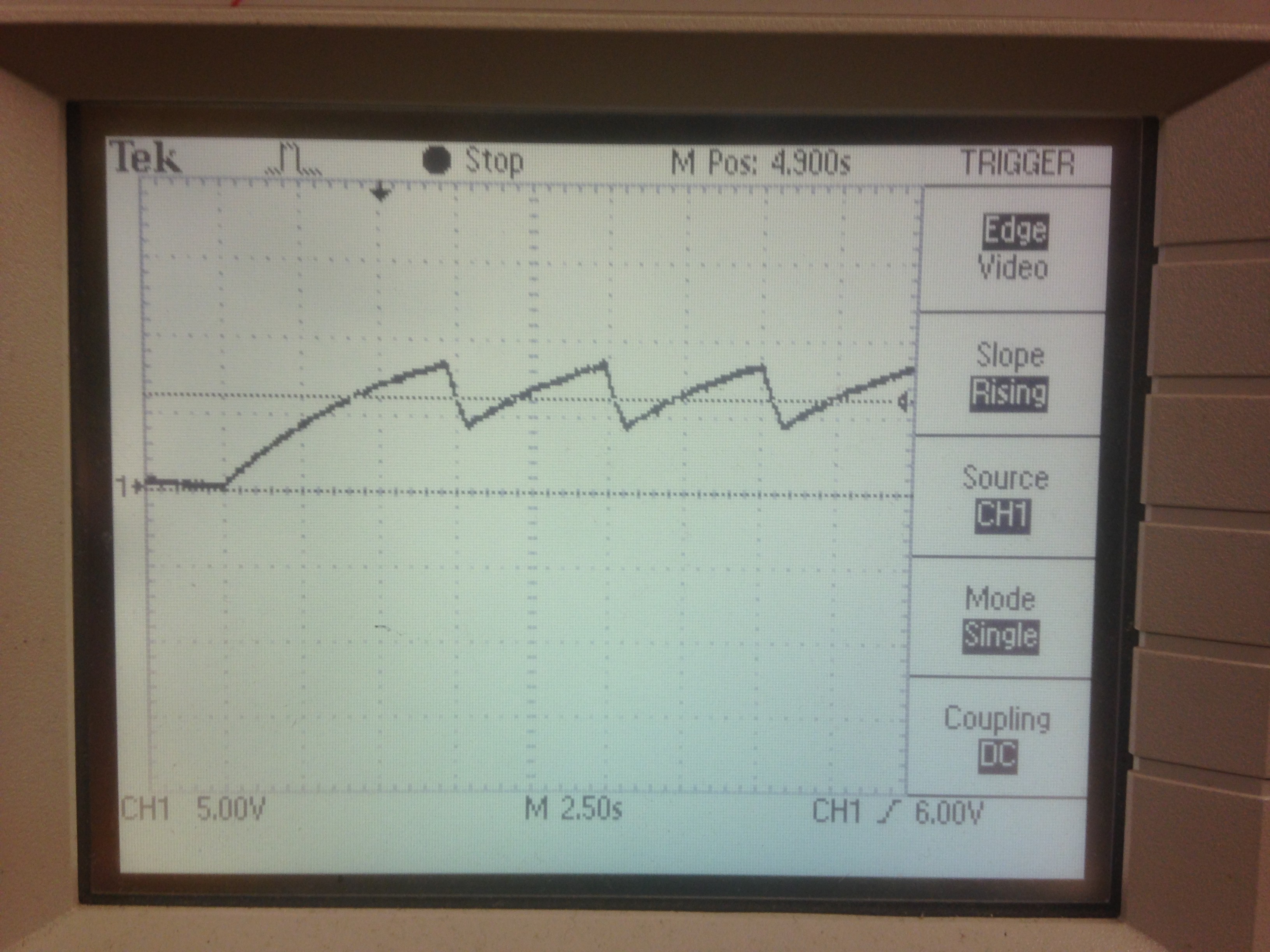
However there was a slight side affect: it seems the first interval is longer than the proceeding intervals, is is cos the reset pin doe not only pull the output low but also pulls the threshold pin low and thus it takes longer to charge to the upper threshold (about 40% longer), which can be shown from this scope grab of monitoring the threshold pin:
![]()
as it can be seen; the time taken to charge to the upper threshold on the first period is much longer than the second, third, forth etc.
I was testing this with the resistor value for a 5 second interval. Measured the difference between the first and second interval (N.B. the interval is the time between the relay being de-energised and then re-energised). First was 8.5 sec and second was 5.2 sec. I then change to the highest interval resistor value and repeated: first was 53 sec and second was 33 sec.
Given that at the greatest interval I would hardly notice whilst driving, I could live with this side affect, so long as I get my first immediate wipe!
-
Selecting a switch and Building prototype
05/03/2017 at 22:38 • 0 commentsFinding a switch
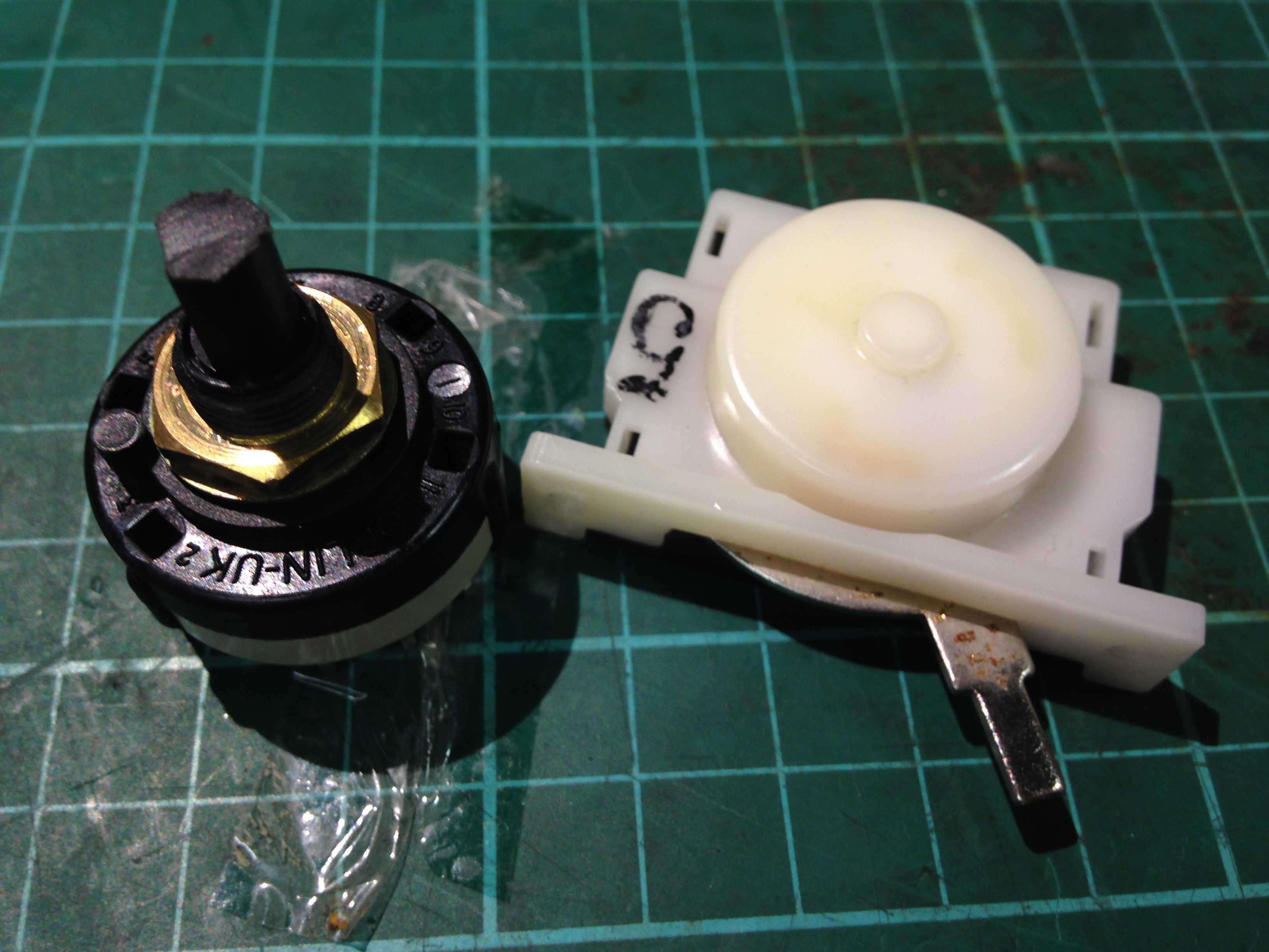
As usual I first looking in my spare parts box for bits, I found 2 candidates for my switch that would select the interval for the timer:
![]()
Action is important in this case, it has to be a very positive 'click' and hold its position firmly as not to change whilst driving along. The white one on the right had a slide action and all the attributes I needed, but unfortunately had strange contact configuration! the Black rotary switch on the left had the same attributes, was single pole and could have up to 12 contacts, which could be configured by moving a ring with a tab in it under the nut. So a clear winner.
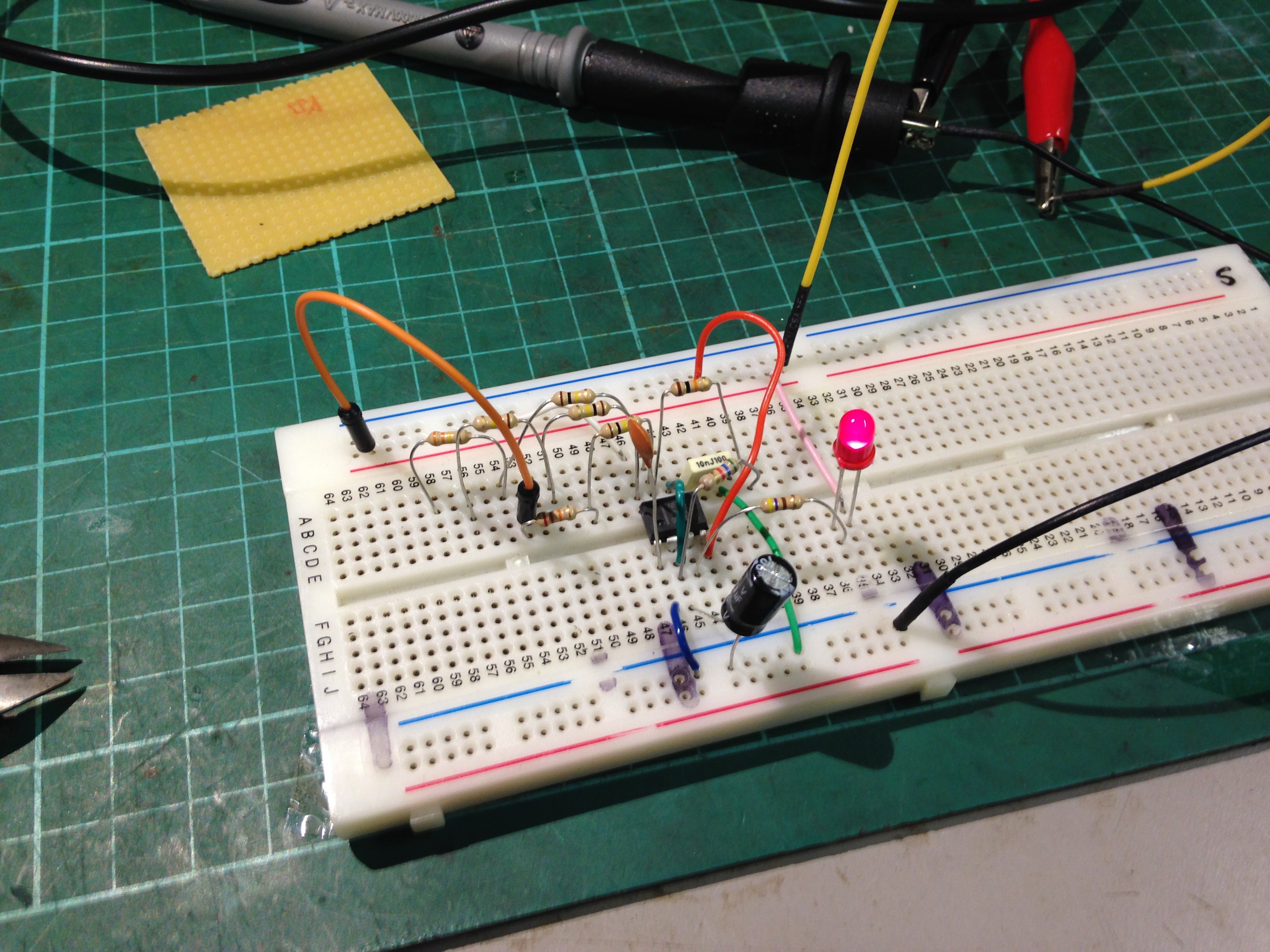
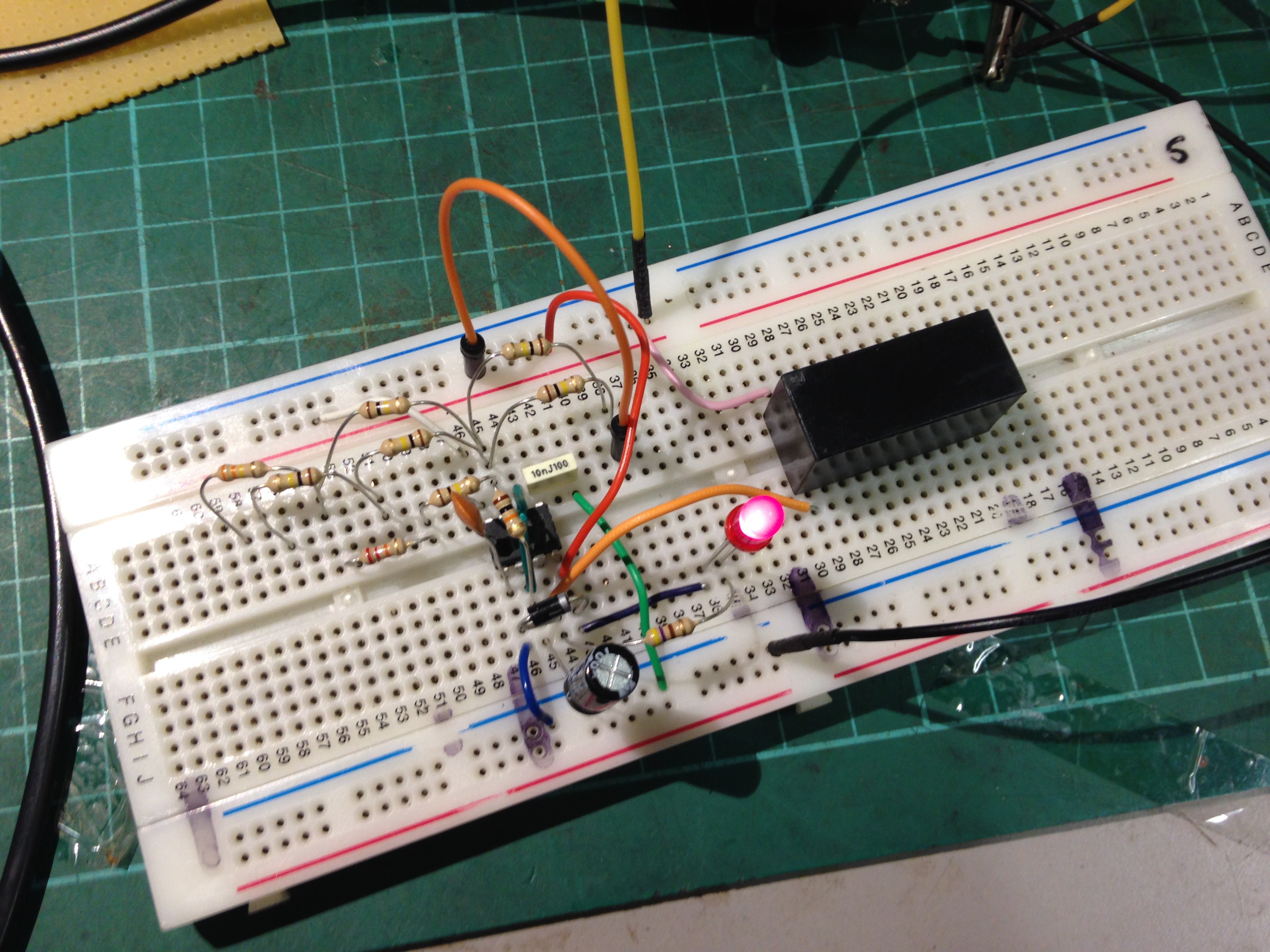
Building the prototype
![]()
Firstly I determined what intervals I wanted: 10 seconds, 15 seconds and 30 seconds. This allowed me to work out my required resistor values for R1 from the 555 astable equations.
![]()
I choose C1 = 100uF and R2 = 15k (10K+4k7) so the time the LED is on for would be ~1 second.
I then constructed the circuit with my calculated values onto breadboard, powered it on and gave it a try. Testing the interval with a stopwatch for each different resistor and watched the LED, it was found they were close enough to what i wanted.
Interval required Resistance Recorded interval 10 sec 120k (100k+2x10k) 10.85 sec 15 sec 200k (100k+100k) 16.75 sec 30 sec 430k (100k+330k) 35 sec So not too far out. I then decided I wanted a 5 sec interval too:
Interval Required Resistance Recorded interval 5 sec 50k (2x 100k ||) 5.19 sec So no problems there either.
I then wanted to expand the circuit further by fitting a relay to the output. First I found a 12V relay in my parts, and then measured the current when energised through the coil: 53.2mA
I bit the bullet and hooked it up directly to the output of the 555 timer and was confident the output wouldn't suffer and it didn't, worked ok.
![]()
I then decided to remove the 4k7 making up R2 and left it as 10k, the change in on time was negligible to detect by the human eye and ear.
From this testing I had my concerns about the drive capabilities of the 555 and am considering using a PNP transistor to handle driving the relay instead of the 555 output directly.
Landy Wiper Control
Sick of having 2 speeds for my windscreen wipers. Nothing a 555 timer can't fix!