Hardie
-
'Buoy One' Test Bed
08/11/2014 at 17:40 • 0 commentsAfter having all of the parts arrive, except for the new propulsion, something could be put together. Initial 3D-printed parts were used to keep most of everything organized. See the images below. The parts will be iteratively improved over the coming months. To keep things open the cad models will be made available on Github and a Thingiverse page. Extra effort was put in to start using FreeCAD to make these changeable by the community.
![]()
![]()
![]()
![]()
This is essentially all of the electronics that will be placed in a single buoy (Except the motor drivers). The wireless charging coil can be seen at the bottom which runs to a LiPo cell charger. The LiPo itself is wedged in the middle of the 3D-printed container. The 3.7V from the LiPo is up-converted to 12V, depending on the need of the driver circuit. This is then used to feed a 5V and 3.3V regulator. These will run the following devices: a micro-controller, GPS, compass and transceiver. Notice the 2 bolts protruding out the side of the holders, these will be used lator on to fix the part on the inside of the PVC tube.
The transceiver itself has caused a heap of grief. Basically hours of debugging, even involving some university spectrum analyser gear, only to find the transceiver was or became faulty before testing. A quick replacement got everything transmitting and receiving 100%.
With this test-bed/cable-tie monster development has started on the communication protocol. Next post will hopefully be of the controller GUI interface.
-
Buoy-One parts close
08/07/2014 at 19:51 • 0 commentsBuoy 1 parts are close, meaning that the first prototype can almost be assembled. In the mean time the GUI interface for the controller is basically finished and waiting for a course to talk to. Will upload a video of the GUI for some critique after contact has been made with 'Buoy One'. Here is just a nice diagram of what the controller looks like at the moment. A RF24 chip will still be added along with some other small bits.
![]()
-
Waiting on Modules
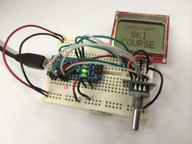
08/05/2014 at 18:37 • 0 commentsAt the moment, not too much is happening in the electronic-hardware department. Currently we are waiting on NRF24L01 modules, wireless charging modules and some boost converters. The RF modules out of these are really the ones keeping us behind. Nevertheless, the all important work of building an intuitive user interface has begun.
![]()
The controller, or ISBController as named in the Github Rep, will be the sole means of communicating with the course. It will be responsible for sending commands, receiving alerts as well as regular updates. For now, a simple user-interface framework has been written to start populating menus.
![]()
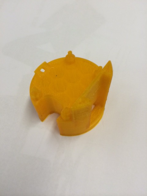
In this waiting process 1 of 2 main internal plastic structures have been developed (iteration 2 in the photo). This part will be responsible for housing the GPS, compass and transceiver at the top of the PVC pipe. A simple bolt mechanism on the side allows this section to be fixed flush at the top of tube.
-
A change of Propulsion
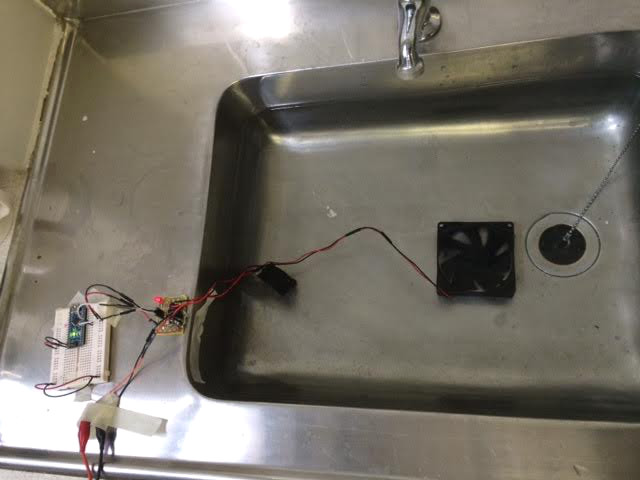
08/01/2014 at 15:07 • 0 commentsThanks to comments from Jonathan Groff, I have investigated the longevity of the PC-Fan motors underwater. Story made short, 1 Fan lasted 90 minutes while the other fan started showing signs of deterioration after 180 minutes. The main cause was corrosion on the pcb of the fan. It might be possible to insulate these in a ball of grease or something similar. However after taking 1 apart, I decided the effort was futile. Therefore PC-Fan propulsion will be declared a fail (Lesson learned: Dont trust a 5 minute water test).
![]()
These fans were chosen for their cost (3$ each) to keep the overall buoy cost down to around (40$-50$). The options left to us are using brushless-dc motors (Used in the OpenROV project) or bilge pumps (Recommended and used by Jonathan Groff). Brushless dc motors, commonly used on multi-copters can cost around 20$ each including the ESC, which will max out the budget for 2 motors. Bilge pumps like the Rule 360 or Rule 500 come in at around 22$ each which is also too expensive for this project (See the ROSIRA for an interesting single bilge pump with solenoids solution that might be a viable option for forward and reverse functionality). However, small submersible pumps available from Banggood.com have been ordered for $2 each which are cheap enough to simply give them a try. They might not be strong enough but that will be tested once they arrive. If this does not work, the slightly more expensive options may need to be implemented.
http://www.banggood.com/Mini-Submersible-DC-Motor-Pump-3V-120L-Or-H-Low-Noise-Max-Lift-p-87235.html
-
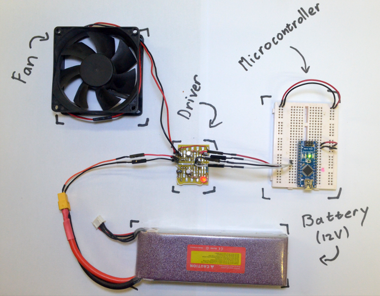
Propulsion Driver Board
07/30/2014 at 18:28 • 0 comments![]()
Hardware:
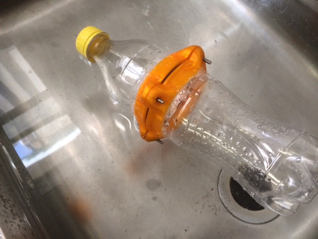
The next step is to build some simple drivers for the propulsion motors. Each buoy is propelled by 2 differentially operated PC fans. Sadly, these fans are only 1 directional. To solve this at a later stage they can be mounted back to back with another set, or be totally replaced by a different type of motor and propeller. Nevertheless, they are cheap and available all around the world in standard sizes. A simple bathtub test, with a 60x15mm fan mounted on a bottle, showed some promising performance.
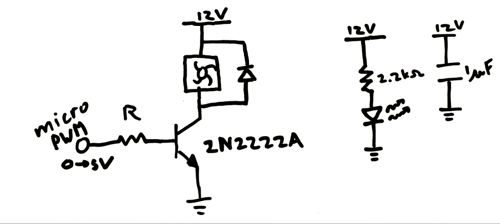
Because each fan is simply 1 directional, there is no need for an H-bridge. Each motor can be driven using a simple transistor as an on and off switch. To enable a manner of thrust control, each of these switches will be driven with PWM.
For the switch, a BJT or Mosfet can be used. Due to the availability, a BJT was chosen in an NPN configuration. This kept the maths simple and the micro-controller safe. Additionally a free-wheeling diode was added over the fan to remove those nasty inductive-switching currents. Finally to take the edge off of things a 1uF capacitor was placed over the 12V rails close to the switching transistors.
![]()
Reading the datasheet, the transistor-gain (Beta) is about a 100 at our conditions. To make sure the PC Fan is fully turned on, I_CE was chosen at 200mA. Therefore, the base current (I_BE) needed to be 2mA. Using a current loop from the PWM pin, a value for R was calculated:
R*I_BE + 0.7 = 5
R = 2.2 kOhm
A darlington pair can be used to minimise the micro-controller sourced current, but this is probably not necessary. At saturation the NPN transistor will have a V_CE voltage of about 0.3V. Taking our designed 200mA, a total of 0.06W of heat will be generated in the transistor. Using the thermal resistance for a TO-18 case (300 degrees/Watt) the junction temperature can be calculated.
25 + 300*0.06 = 43
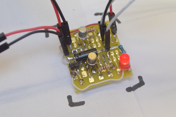
This is well below the absolute maximum ratings. Running for several hours, the ambient temperature inside the enclosure will rise. This could be experimentally tested using a temperature sensor during the initial ‘wet runs’. Below is an image of the prototype driver board with its 2 PC-fan drivers.
![]()
Software:
A simple piece of driver code is added to mask the PWM functions and make the overall code more abstract. This code has 5 functions which are self-explanatory. This will be the first software for this project. The github link can be found at the end of this post. For prototyping an Arduino Nano V3 was used, this might change to a pro-mini later on to minimise BOM cost.
void setupMotors(int leftMotor,int rightMotor)
void setLeftThrust(int thrust)
void setRightThrust(int thrust)
int getLeftThrust()
int getRightThrust()
Additional to the motor-driver file, a pin-definition header file has also been added. This should keep things organised as the code grows.
Github Repository:
-
Waterproof Electronic Enclosure
07/28/2014 at 15:26 • 0 commentsThe first step in constructing an autonomous buoy is to design a suitable-rugged enclosure for the electronics. This enclosure should be easily replicated by anyone anywhere at a low cost point. Here are three possibilities:
A 500ml Coke bottle cut in half to add the electronics. The bottle would then be resealed with 3D-printed brackets and some silicone. This would enable anyone to construct the enclosure with access to a 3D-printer and a bottle of coke. Below is a photo of the attempt. It was found that sealing the 3D-printed parts to the bottle proved difficult and did not prove to be rugged enough.
![]()
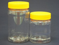
A plastic honey-jar available from a nearby factory. These jars come in very cheap and are already equipped with a screw-able lid. However, these jars may not be available as a standard across the world and was immediately discarded.
![]()
Image from http://www.plic.co.za/
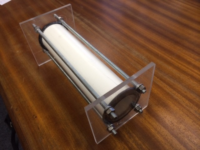
The final design which has been chosen for the project is a PVC pipe sealed ends. PVC is available everywhere in standard sizes and Perspex can easily be obtained. In this design a PVC pipe is sandwiched between Perspex using 4 threaded rods. This enclosure proved to be extremely rugged and 100 percent waterproof.
![]()
This was simply a waterproof test model. The final model would have rounded Perspex ends which will be manufactured on a CNC machine. The only problem with this design is the effort needed to open the container by unscrewing 4 bolts. This will affect the design of the electronics. Wireless charging and over the air programming will need to be implemented to make the design practical.
The bill of materials is as follows:
4 x Threaded rods (M6 Length: 230mm)
1 x PVC pipe (Diameter: 50mm Thickness: 2.5mm Length: 200mm)
2 x Rubber washers
2 x Perspex ends
12 x nuts and washers (M6)
Silicon sealant to seal washers to PVC
Intelligent Ski-Course
Autonomous buoy network for a slalom-ski course connected to your ski, deployed by simply throwing it all overboard.