Husarion
-
ROSbot manual is ready
12/12/2017 at 17:23 • 0 commentsWe have also created technical specification for ROSbot: https://husarion.com/core2/manuals/rosbot-manual/ . Find more details about our project here.
-
general overview
08/06/2017 at 21:10 • 0 comments![]()
![]()
-
red & white
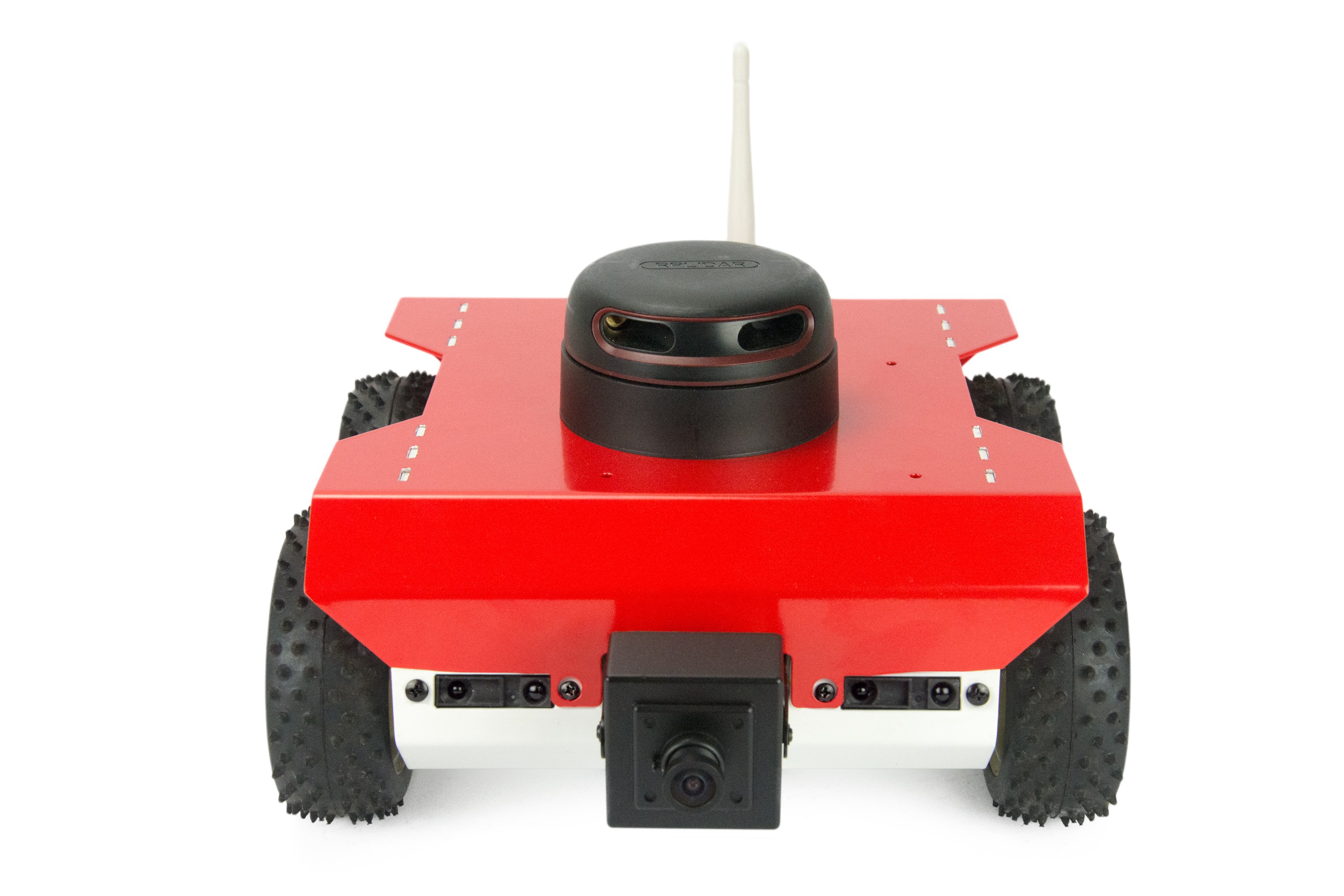
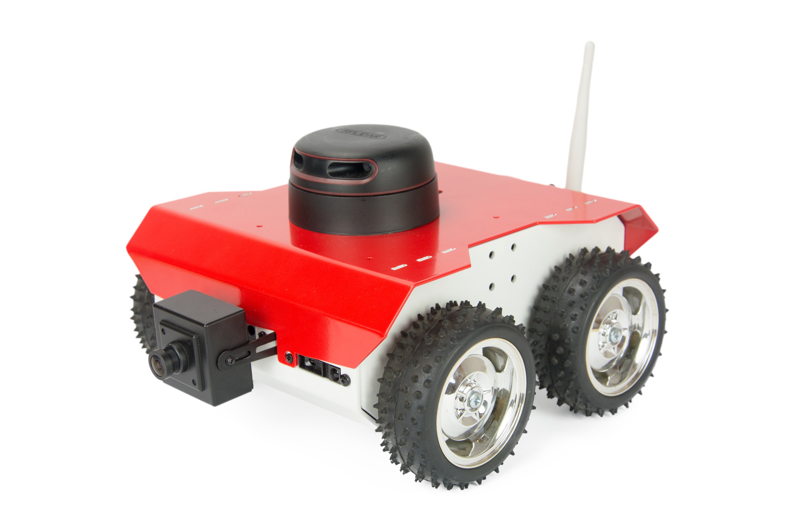
08/04/2017 at 14:54 • 3 commentsLastly, ROSbot received a paint job! See the new and improved ROSbot below:
![]()
![]()
![]()
Check out more at https://www.crowdsupply.com/husarion/core2
-
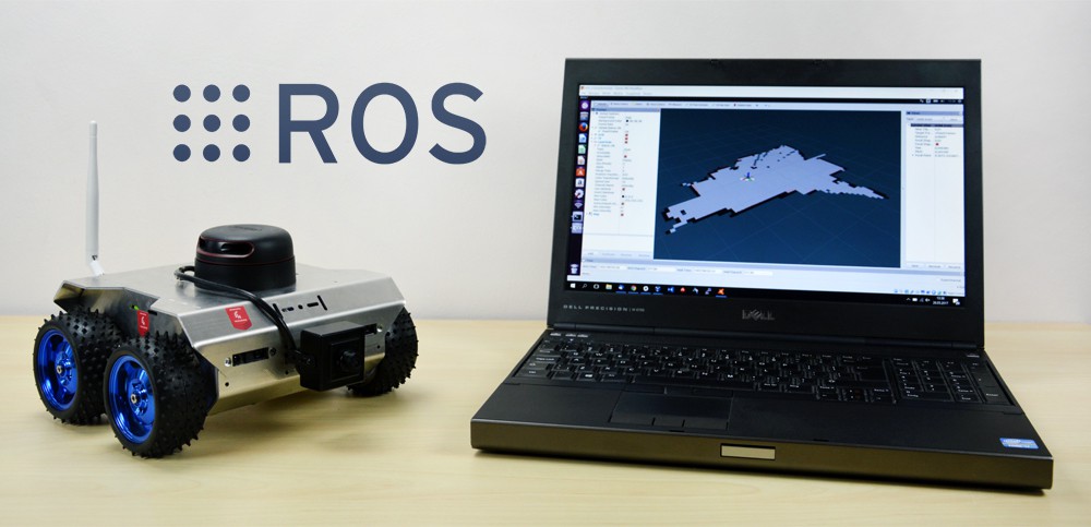
ROSbot video & 2 new ROS tutorials
07/18/2017 at 19:32 • 0 commentsTake a look at a short video presenting ROSbot in action:
We've also created 2 new ROS tutorials. Now there are 8 lectures to help you get familiar with a set of software tools that powers modern robots:
- ROS introduction
- creating nodes
- simple kinematics for mobile robot
- visual object recognition
- running ROS on multiple machines
- SLAM navigation
- path planning
- unknown environment exploration
-
More info about the connector board
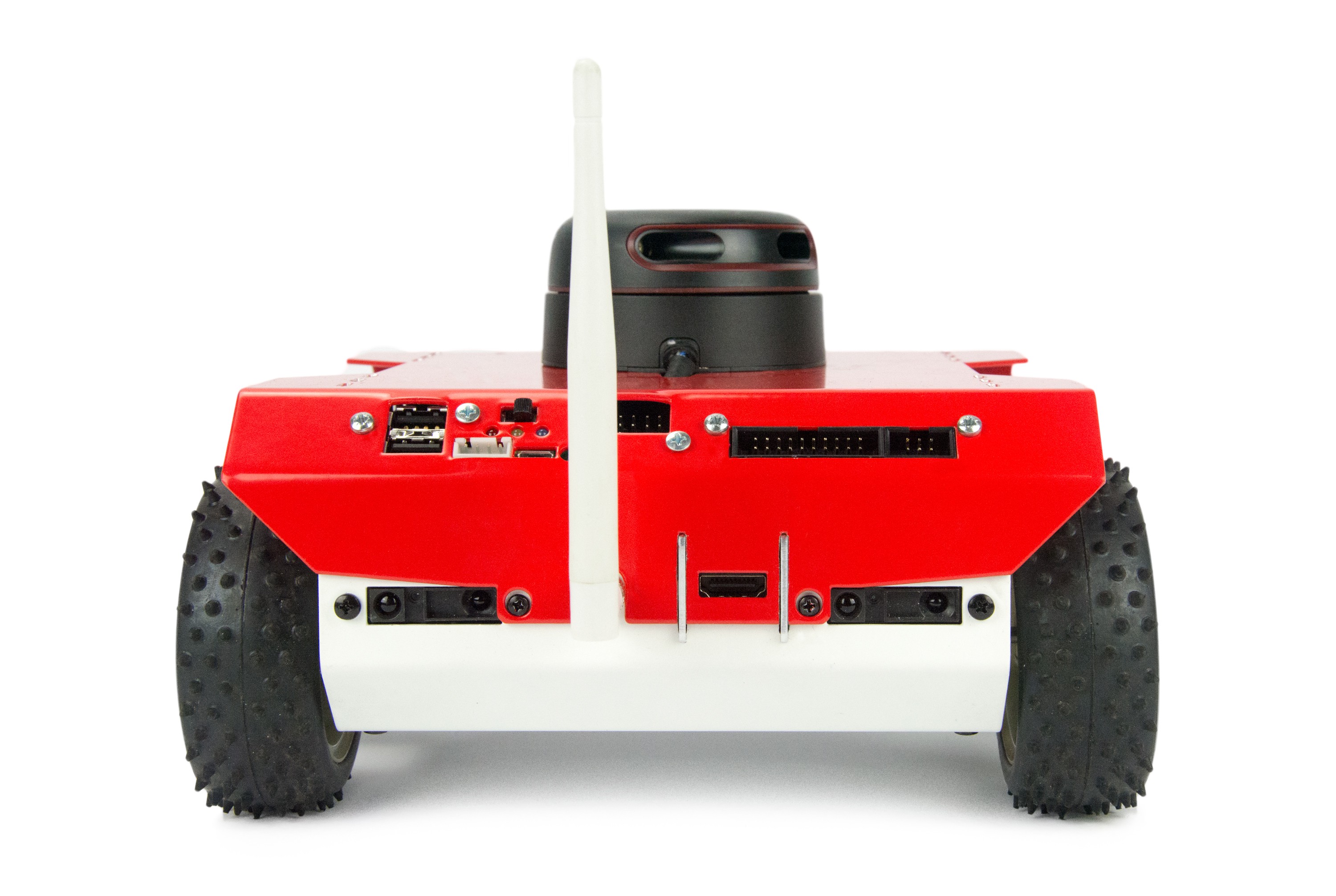
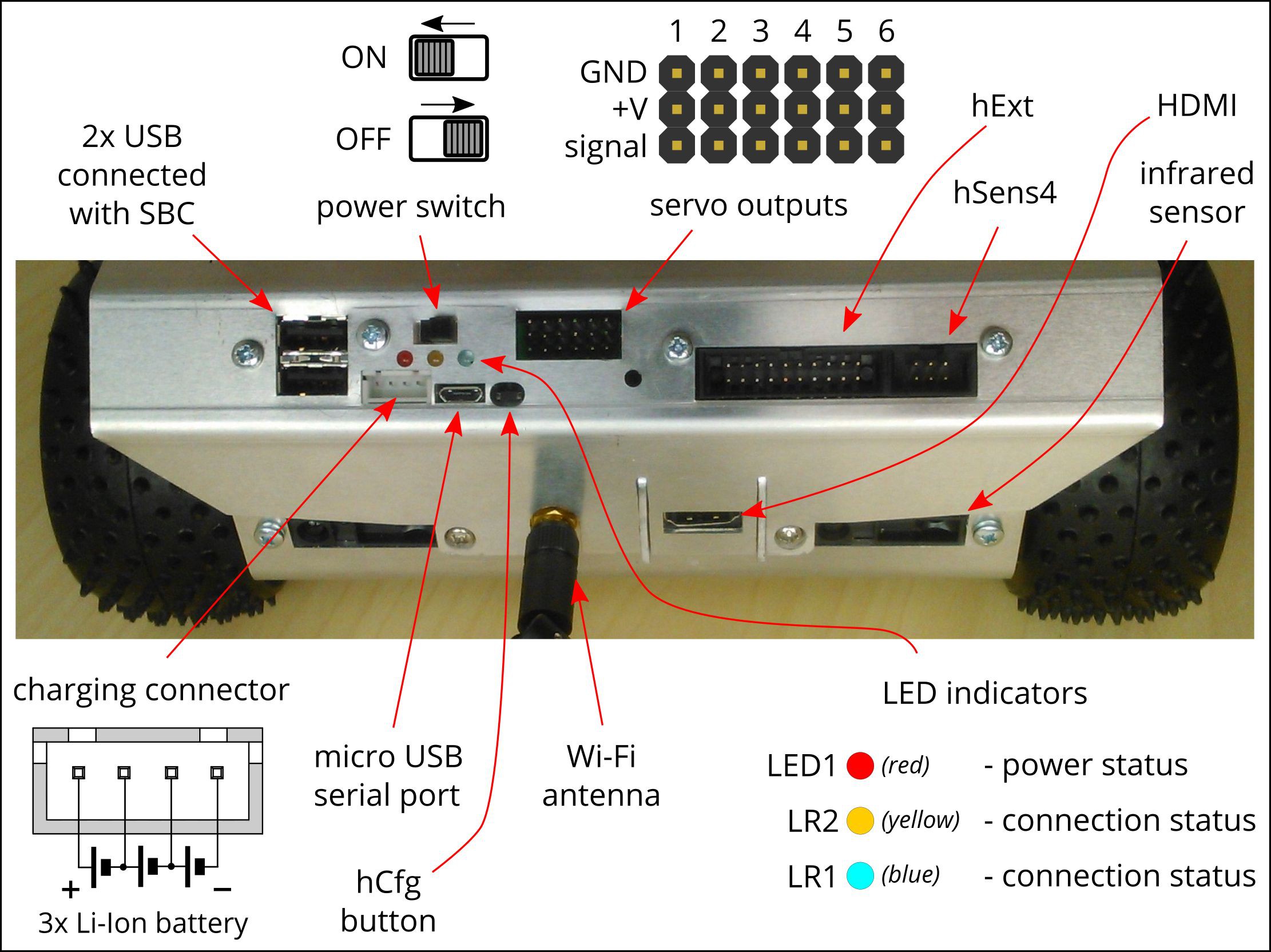
07/14/2017 at 18:40 • 0 commentsWe prepared the picture that explains a bit more about the new, rear panel:
![]()
Two of USB ports of SBC (ASUS Tinker Board) are occupied by LiDAR and the camera. The other two are available on the rear panel which you can use to connect a Kinect, a keyboard or a mouse. Connect an HDMI screen and you can start debugging directly on ROSbot which comes with preinstalled Linux operating system. You can also connect an LTE modem if you like.
The servo outputs, hExt and hSens4 ports are described in our documentation which you can find here: https://husarion.com/core2/hardware/ .
It's very important not to draw energy from Li-Ion battery under critical voltage level - it can cause a significant decrease of battery life. The firmware is constantly checking the battery level. If voltage level is too low, LED1 are blinking, motors are stopped and user is notified that it's time for charging.
We also decided to have RP-SMA connector for the external antenna, rather than connecting a Wi-Fi dongle. ASUS Tinker Board uses I-PEX MHF4 antenna connector, which is even smaller than much more popular u.FL. Watch out not to damage the 0.8mm RF cable that fits in MHF4 plug. We have protected the cable with two layers of heat shrink tube and stiffen the cable in the way that guarantees that the MHF4 connector will not be pulled out by accident.
-
introducing ROS tutorials for ROSbot
06/29/2017 at 20:38 • 0 commentsWe are introducing ROS tutorials for ROSbot. The first 6 lessons are available here https://husarion.com/core2/tutorials/ros-tutorials/1-ros-introduction .
Covered topics are:
- ROS introduction
- creating nodes
- simple kinematics for mobile robot
- visual object recognition
- running ROS on multiple machines
- SLAM navigation
Check it out!
![]()
-
ROSbot 2.0 is ready!
06/28/2017 at 10:19 • 0 commentsHere is the list of improvements made in ROSbot 2.0 - autonomous robot development platform:
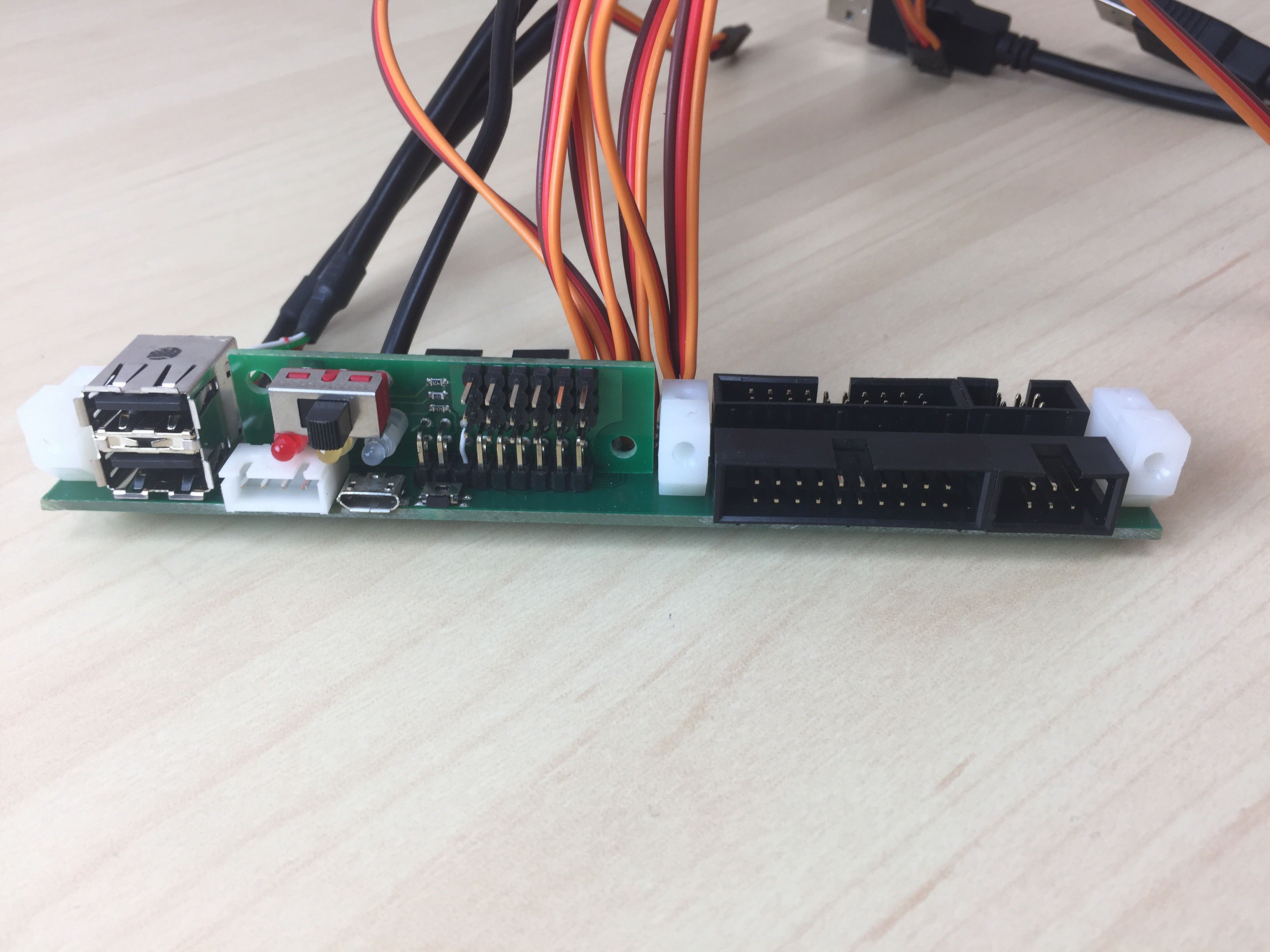
1) unused ports from CORE2-ROS are now accessible on ROSbot chassis, so you can add the external modules to your ROSbot thanks to:
- 2x host USB
- 1x USB serial (powered by FTDI chip)
- HDMI
- Li-Ion charger connector
- Extension port (12 x GPIO, 7 x ADC, SPI, I2C, UART, 2 x ext. interrupt)
- sensor port (4 x GPIO, ADC/ext. interrupt, I2C/UART, 5 V out)
- 6 x servo port with selectable supply voltage (5 / 6 / 7.4 / 8.6 V) 3 A cont./4.5 A max. current for all servos together
- hCfg button for Wi-Fi config, 3 LED's and a power switch
![]()
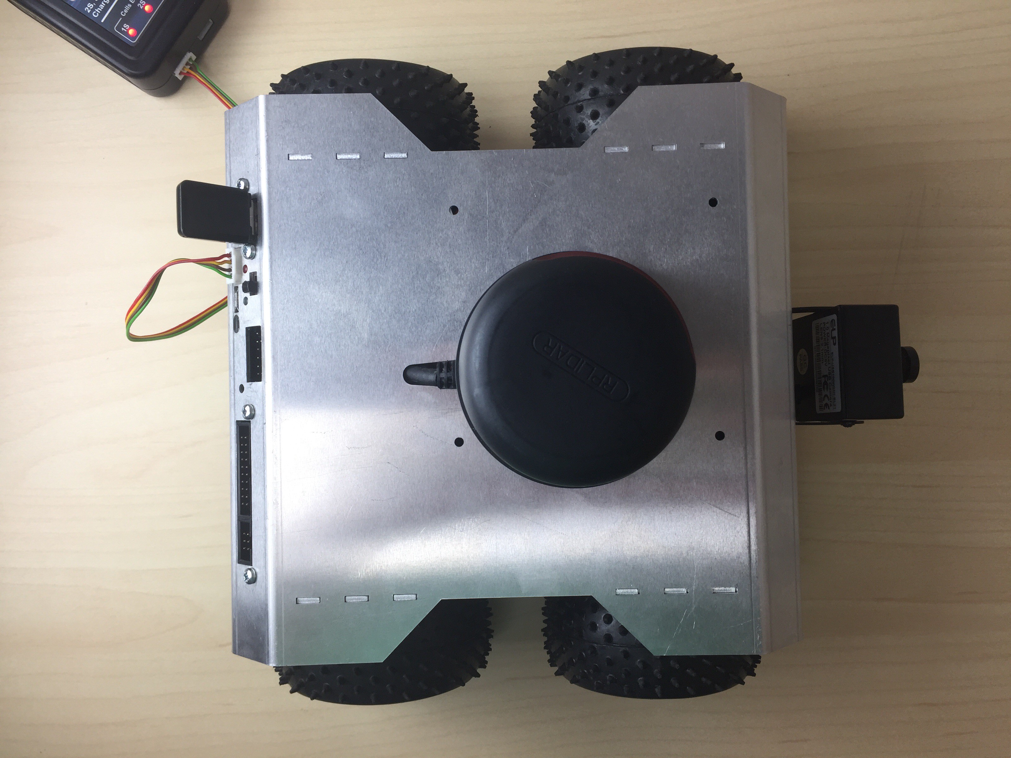
2) LiDAR and camera cables are hidden inside chassis
![]() 3) In the default configuration ROSbot includes CORE2-ROS with ASUS Tinker Board instead of Raspberry Pi 3 because of high computing power needed to realize advanced ROS functions (eg. SLAM navigation)
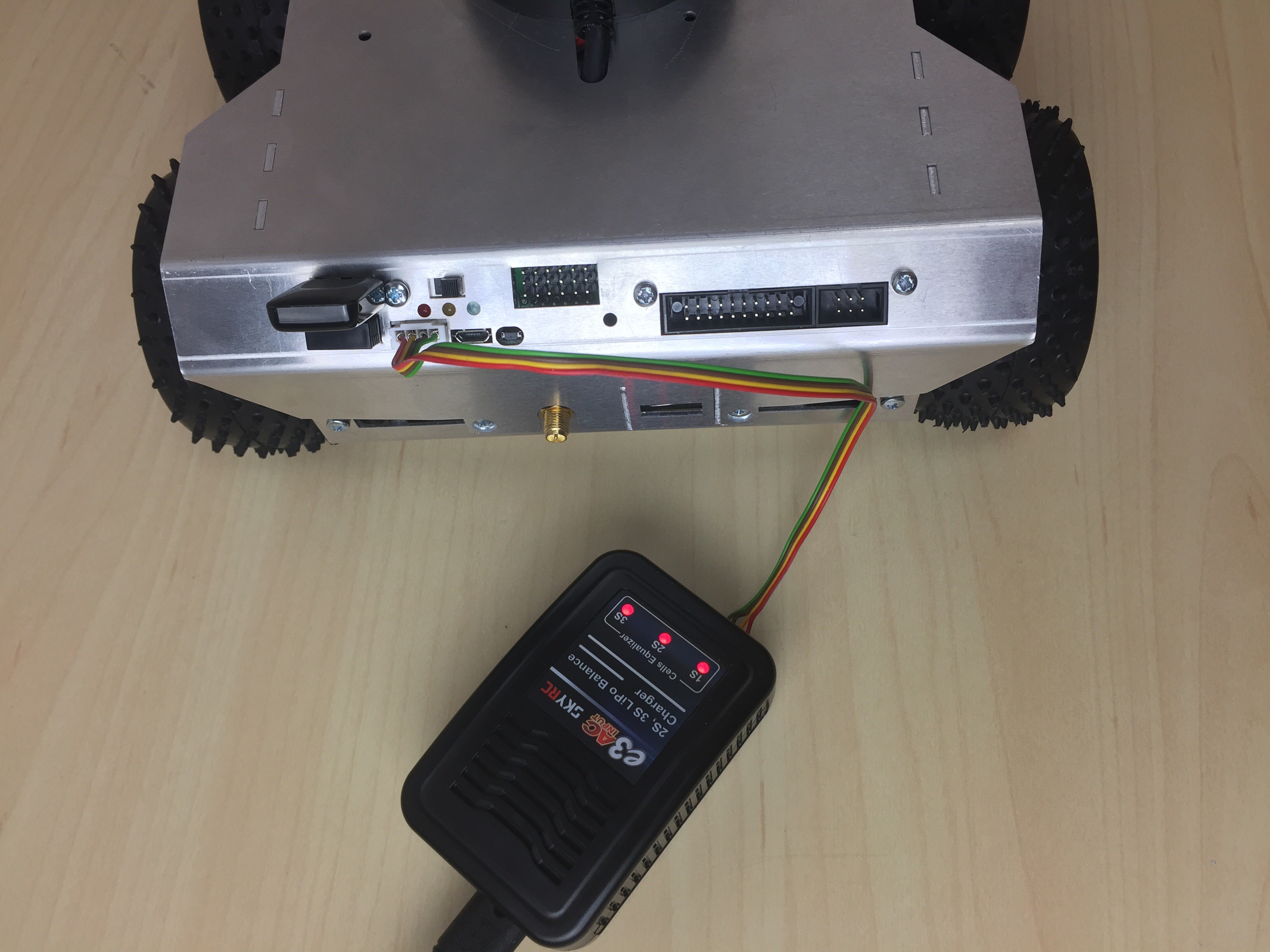
3) In the default configuration ROSbot includes CORE2-ROS with ASUS Tinker Board instead of Raspberry Pi 3 because of high computing power needed to realize advanced ROS functions (eg. SLAM navigation)Because the charger connector and unused ports are accessible from the ROSbot chassis you don't need to remove the cover to charge Li-Ion batteries or add your own modules. To make it possible, we designed this additional adapter board:
![]()
ROSbot is a nice alternative to Turtlebot if you want to learn more about ROS, experiment with robot swarms or make your own autonomous robots. We hope ROSbot - autonomous robot development platform for hackers - will be a base for your new robotic projects.
-
The way of creating the mechanics
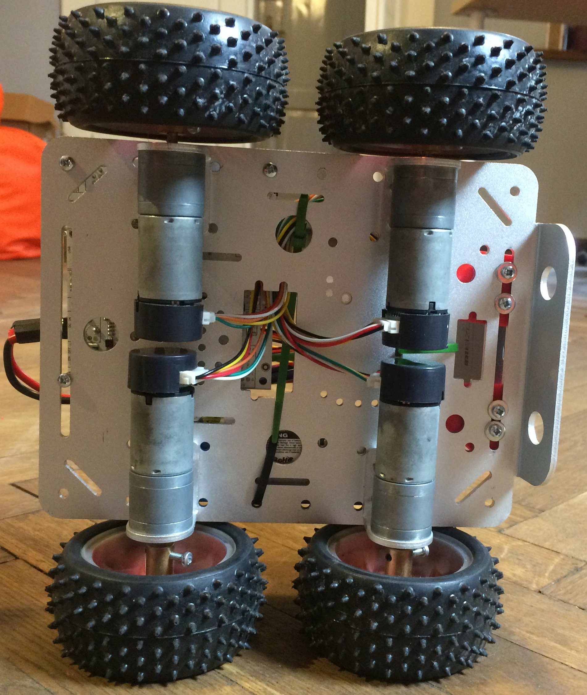
05/26/2017 at 12:37 • 0 commentsAt first we tried the ready to use, 4WD robot-chassis that you can find by name "C300 intelligent car chassis" ;)
![]()
Buying a similar chassis is a good way to get a platform with pretty good motors with encoders. It's even cheaper than ordering the motors themselves in popular robotic stores. We installed all parts - CORE2 controller with Raspberry Pi 2, battery pack (3x18650 Li-Ion), a camera, ultrasonic distance sensor and finally a LIDAR. It was working well but not looking well because of not sufficient space on platform and ugly wiring. Oh, I don't even want to show this here.
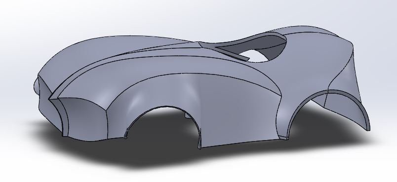
The next idea was "we have a 3D-printer!". The plan was to use the same chassis but with the 3D-printed body covering all the mess, with only LIDAR exposed at the top. This is what the designer drew:
![]()
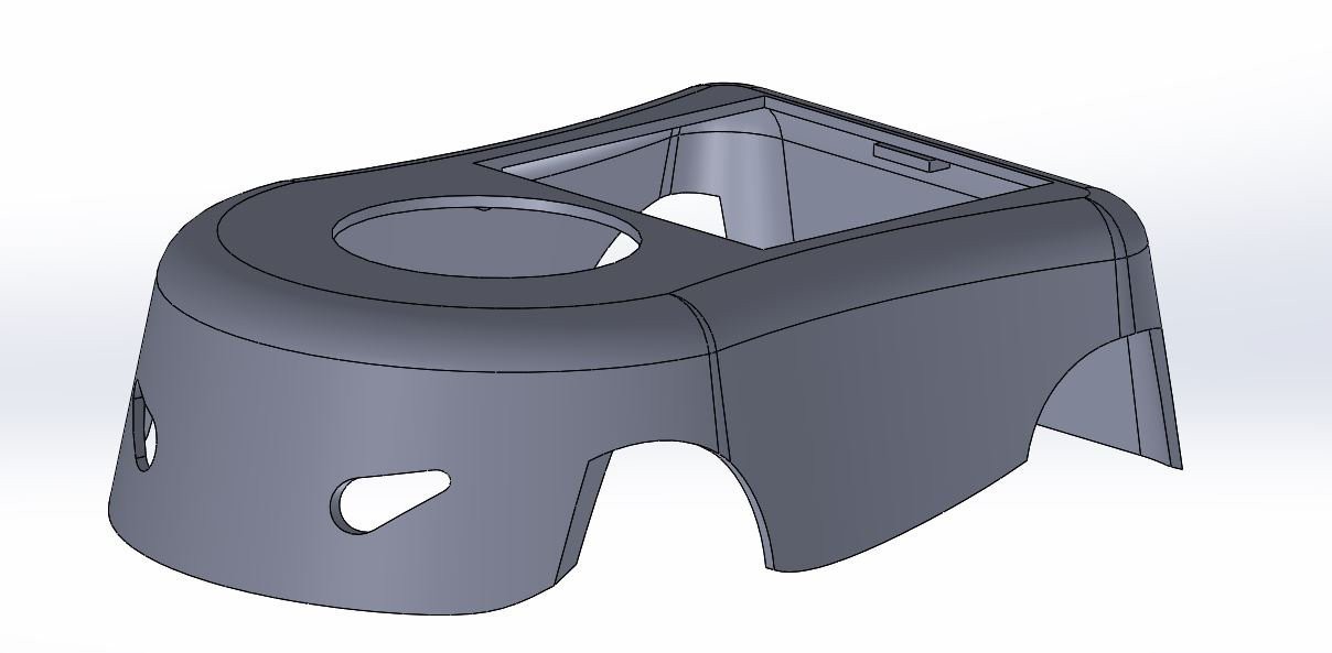
how the engineer brought this project down to earth:
![]()
and how it looked like when we finally made it:
![]()
We noticed that 3D-printed body is nice but not very durable and not easy to modify when we want to add anything to our platform. And the 3D-printed body needs a lot of work with grinding, spackling and painting, and if we wanted to make the second piece of robot, it would probably look differently. That's why we've ordered the metal chassis, laser-cutted out of aluminium. This is the result:
![]()
I've placed more photos in the gallery. We made a few mistakes and we needed to use a file to "move" some holes. And we are going to make a new version with the additional panel for connectors, because some interfaces (HDMI, USB Serial, LED's, hCfg button etc.) need to be accesible from the outside. This is the good topic for the next log :)
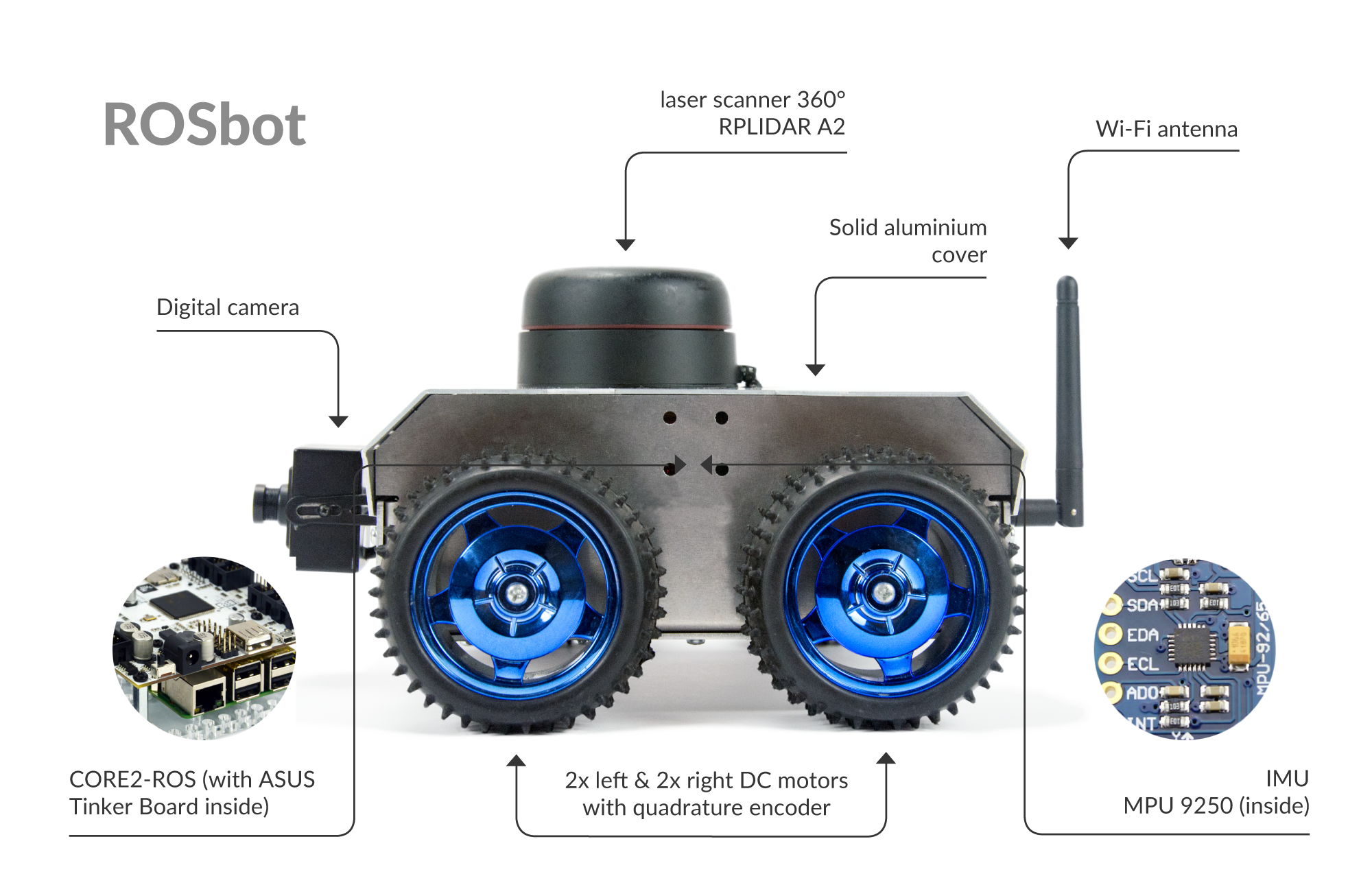
ROSbot - autonomous robot platform
Open source & connected universal robot platform. ROS-powered. Sensors: LIDAR, camera, IMU, encoders, distance sensors. 4 DC motors.