Rue Mohr
-
videos posted
08/13/2014 at 14:39 • 0 commentsI have a number of videos on youtube for this robot.
the Two hackaday videos:
sub 120 seconds:
in excess of 120 seconds:
fun things to do with your robot arm:
makeing it move!
move a dice around!
delete emails on your iphone!
Now the problem I ran into was that its hard to do much with just 1 arm, so now I'm just working on building an army of them. Who likes the idea of a custom cookie assembly line that makes cookies to order from online submissions?
(its ok, I'll quality test your cookie before it leaves :-)

-
Firmware/Software
08/13/2014 at 14:37 • 0 commentsI have written and posted the firmwares. My standard board is an atmega32 board. I'v written it ground up to provide about 12 bit, glitchless servo pulses. To that effect, it only has 8 channels, anymore than 10 requires having two timers at once, and then you have interrupt stalling which leads to timing glitches in the pwm, which leads to twitching of the servo. NO TWITCHING!
(and no, arduino cannot do any better, you just dont have a scope to see the glitches)
Its serial controlled, with a protocol based roughly on the SSC16
The pc software does basic axis interpolating (using my interpolation library!) and timing. it reads from a simple file with lines consisting of a time offset and a list of targets for each servo. It makes sure to take the specified time to get to the position specified on the line. (need a delay? Tell it to take the required time to move one of the axies by .001 units)
I'll get into IK later.
THIS is the firmware for the avr board.
it seems that had links dont work, its:
http://ruemohr.org/~ircjunk/robots/arm7/hobbydriver/
THIS is the PC side software.
http://ruemohr.org/~ircjunk/robots/arm7/pc_software/
huh, it auto href'd it
-
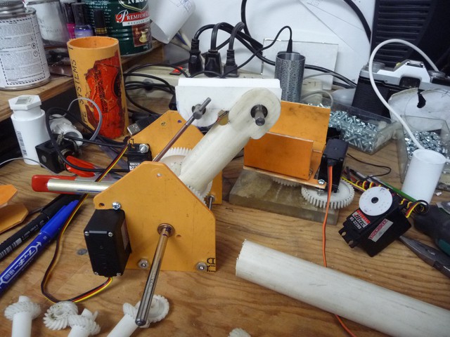
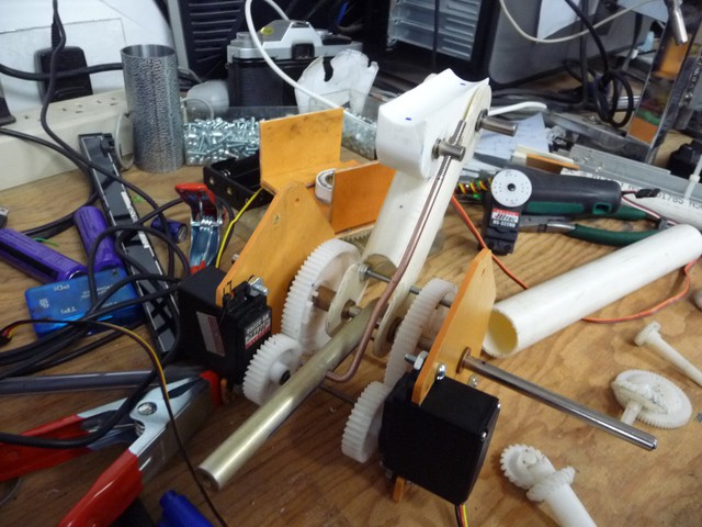
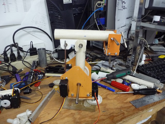
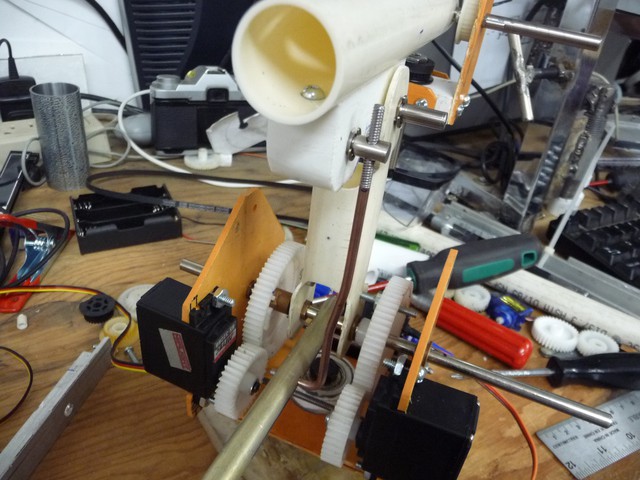
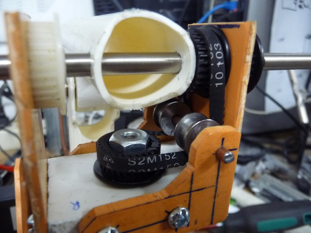
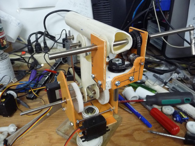
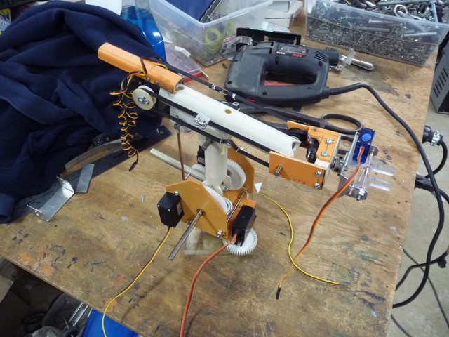
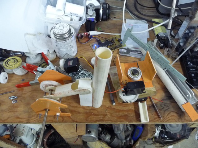
Main mechanical assembly
07/30/2014 at 14:18 • 0 commentsThe flat material used on this robot is flattened PVC pipe, the same stuff seen in the background.
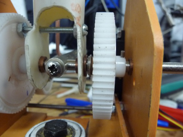
Here is a closeup of how the lower arm is driven. The left gear is fixed directly to the arm segment, but is free of the shaft. The right gear is fixed to the shaft (see pin on right) and operates the lever arm in the middle which is also fixed to the shaft.
The motors are kept back to the base as much as possable to keep the arms weight down.
The rod out the back will be used for counterweighting.
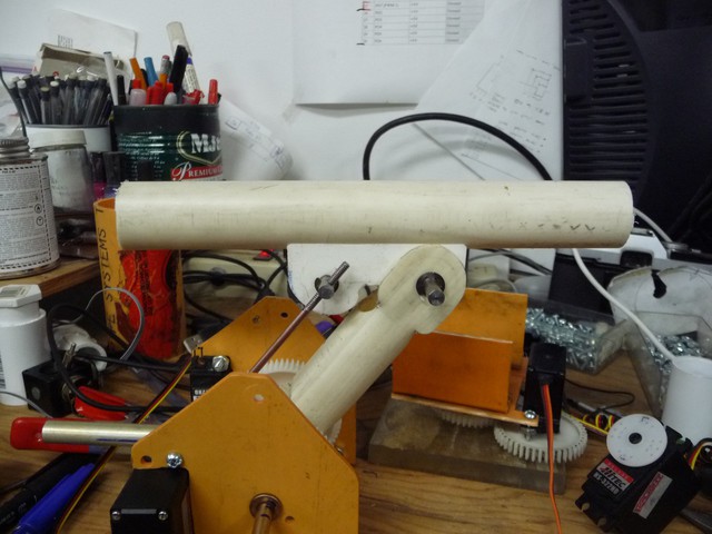
The upper arm segment is 1/2" pvc pipe
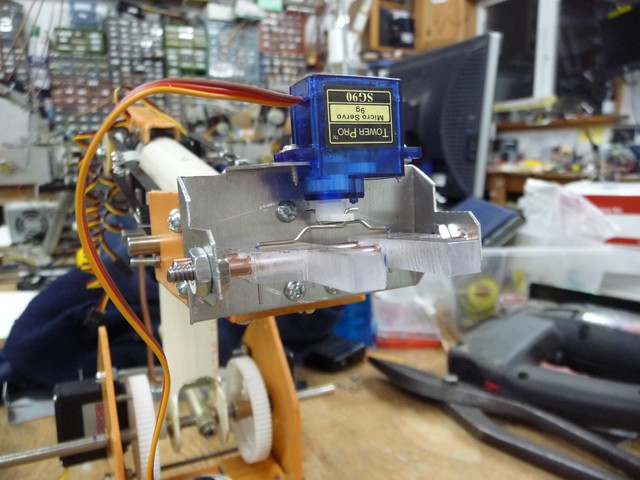
Here I'v mounted the upper arm to the base. The wrist pitch and twist goes togethor next. Motors will go on the back end of the arm to counterweight the gripper end.
The forearm is attached with a new trick, the screw is down in the pipe, with a hole above it big enough to fit the screwdriver.
I wanted to use bevel gears for operating the twist, but didn't have any that would work for this, so I tried something new, and used a synchrobelt with some pullies, its a bit stiffer than gears would be, oh well.
I thought I has some suitable pullies, but the centre holes were wrong, so these ones are custom done on my lathe.
If there is one thing I'v learned, its to cut the shafts short at the end of the project.
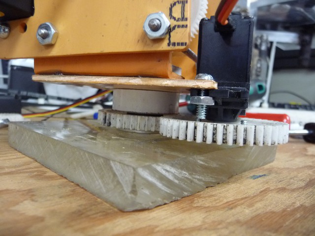
Here is a better shot of the base 'stack', the bottom gear is fixed to the base.
Robot arms should not teeter on the shaft of a servo!
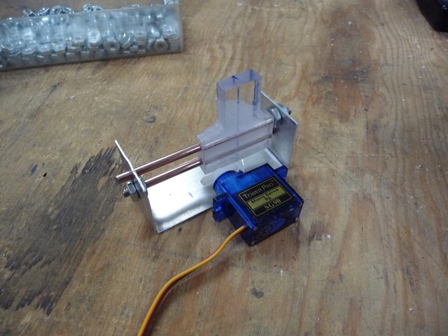
Next comes the gripper. I like parallel jaw grippers, and I was considering doing this like an armatron, but didn't want to deal with so many peices, I also wanted something small.
This idea came to mind. These fingers slide along rails, linkage wires go to either end of the servo horn, with the right linkage wires, they will meet in the middle.
rebuilding the bracket to accomidate the servo plus a bit of artistic angles, and bingo
The nice thing about pvc is that it can be glued really easy, Here I'v come up with a bracket to hold the upper motors. I didn't even worry about belt length, the whole span of the belt isn't being used and I can have a linkage in it.
I suggest the linkage style used on the back belt, the method used in the front one is just a pain.
a clothespeg spring works to keep the belt tight.
Next I have to mount it to a base and put in all teh counterbalance weights and springs....
-
Initial assemblies
07/29/2014 at 14:09 • 0 commentsAssembly of the hardware has gone roughly like this:
On the right is the base assembly. I was able to use the lathe to open up some 1/2" PVC pipe fittings just enough to fit a skateboard bearing. Two of them in either end of the pipe coupling hold the base onto a king bolt that goes down to the piece of 1/2" Plexiglass I'm using as a base. In the sandwhich of pipe bits (funny how you notice how bad a photo is when your trying to talk about it) is a gear that the servos gear will mesh with to rotate the base. (servo moves with the robot) The gear ratio for the base is set to 1:1
On the left you see the initial roughout for the upper arm. I was not going to get fancy, but I couldn't bear to leave out atleast bushings. The gear ratio will be about 2:1 giving me about 180 degrees on the arm joints, which is more than enough.