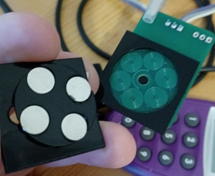
There is a great write up on PCB motors by Kevin Lynagh with links to patents and videos.
I did some more test with the pcb motor;
I am now at a speed of 10 Hertz or 600 RPM. The black plastic is acrylic cut with a laser cutter. The metal parts are pieces from a stanley blade. I use an acrylic dummy prism and the metal blade pieces ensure that the magnets are fixated.
An acrylic piece is kept between the magnets so they do not move horizontally. Vertically they are fixed by the attraction of the metal part. Note that the prism does not has a shaft. There is a hole in the board but it is not used. The shaft is the acrylic holder of the magnets. This rotates in the square support. It can be assumed that the prism is perfect, as it is manufactured with a high tolerance. The acrylic is not perfectly planar. Still if the prism rotates it will most likely end up in the same position.
The PCB motor is pulsed with FPGA and the typical six step commuation loop. I also switch the field off at the end of a move. This prevents it from being slowed down. I need to optimize this further.
My current plan is to simple reduce the duty cycle if the prism speeds up.
I will also replace the acrylic with Teflon. This will reduce the kinetic friction coefficient from 0.4 to 0.03.
I aim to keep the prism in position by either pushing from above or by placing metal under the board.
Metal under the board to create a downward force is possible, but the whole thing is quite "delicate" and interferes with the other forces and risks that the prism doesn't rotate.
The acrylic dummy prism already rotates at 5V and a current of 0.7 Amps. Heat is not a problem if a duty cycle of say 0.7 is used. Temperature is around 50 degrees Celsius.

 Hexastorm
Discussions
Become a Hackaday.io Member
Create an account to leave a comment. Already have an account? Log In.
Problem with the center pole is that it needs to be attached at 90 degrees with a tolerance less than 0.1 degrees. I cannot even reach 2 degrees. I added some pictures of the new design.. There is a hole in the board so it's still possible to add a center pole. Design is not finished yet. I will outline how this is supposed to work probably later.
Are you sure? yes | no
I think with this design, the magnets are being pulled toward the PCB so there should be something ensuring they are aloft to avoid undesirable friction. Also, a center pole is going to be needed because the magnets are trying to move in a strait line which is resulting in jittering or in this case, friction.
Are you sure? yes | no