-
Hacking scanning mirrors in to scanning prisms
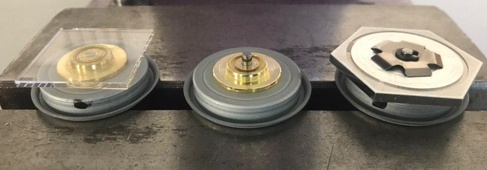
08/21/2019 at 21:12 • 0 commentsThe process goes from right to left. First the clamping pin is removed so the mirror can be released.
![]()
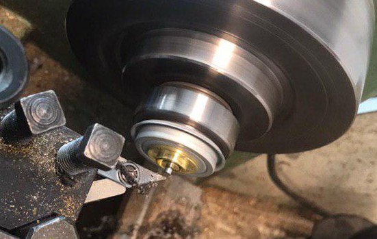
After removing the clamping pin, I removed part of the metal central axis so the first ring can act as reference substrate. I used a spinning mill, a DIY alternative is a hand drill like a Dremel.
![]()
A TESA hite 700 is used to assure that the cut is deep enough, and the inner ring ring is lower than the outer ring. A DIY alternative would be to use a micrometer gauge.
The polygon base is then placed back on the motor. UVacryl 2295 is deposited on the center ring and the prism is placed on top of it. This can be done by gloves or a pen-vac. The distance with respect to a reference pin is measured while the prism is rotated. This assures the prism is centered.
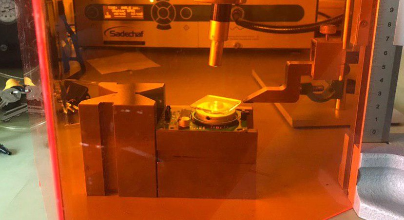
UV light is used to fix the prism in position. I used the blue point 2 from easy cure for 120 seconds. An UV led light at 375 nm suffices as well.![]()
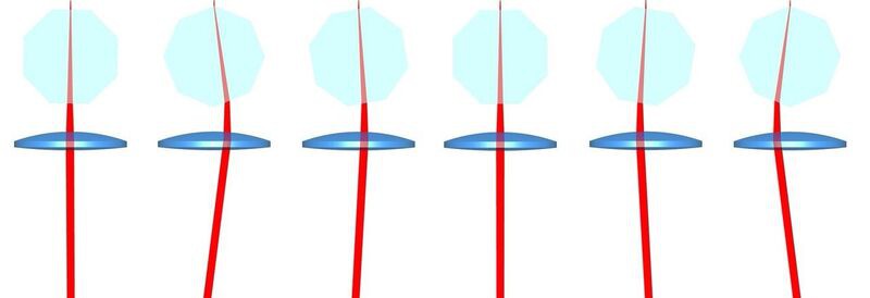
In physics, it is easy to show that being reflective or a mirror has disadvantages. A mirror is four times more sensitive to the facet to datum error than a prism. The facet to datum error is key as it results in the cross scan error which is hard to remove. Jitter can be removed via the photo diode.
If a mirror has a facet to datum error of one degree, the total error is two degrees. If a prism with a refractive index of 1.5 has a facet to datum error of 1 degree, the total error is 0.5 degrees, see deviation angle prism on Wikipedia. -
SX10: wide scan angles with prisms
08/13/2019 at 20:36 • 0 commentsI have found a commercial prism scanner in the field; the Trimble SX10 scanning total station.
![]()
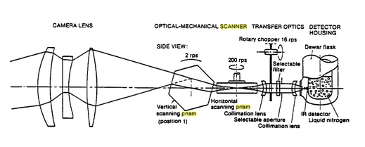
For more details see this article on the big eye. They translate light by refracting it through two orthogonal prisms and then collimate it with a lens. The trick here is that they use it to scan over a wide angle, instead of short angle. They have a sort of reverted setup.
![]()
You can see they start from a point and then form a collimated, aka parallel, bundle.
It turns out that this design was used in the AGA Thermovision System 680 in 1970.The challenge solved by this thermal imaging camera was how to scan [over a wide area] using a single, very expensive, and liquid nitrogen cooled infrared detector. The solution was to pass the beam through two rotating [octagonal] germanium prisms, one horizontal and one vertical.
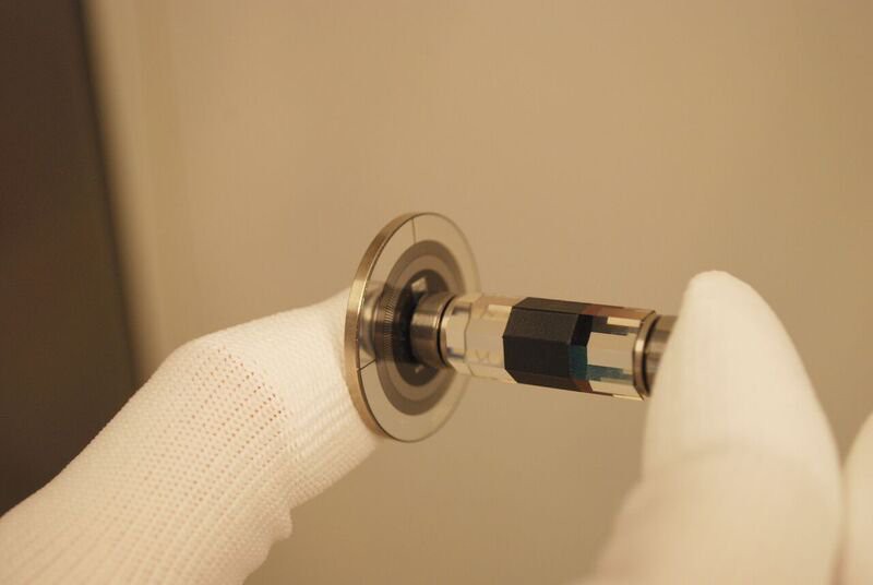
A picture is provided on page 114 from inverse problems in engineering mechanics.![]() The germanium prism is shown here.
The germanium prism is shown here. -
Module improvements
08/10/2019 at 15:04 • 0 commentsChanged the scanner and ported all designs to FreeCad. The scanner can be calibrated via set screws.
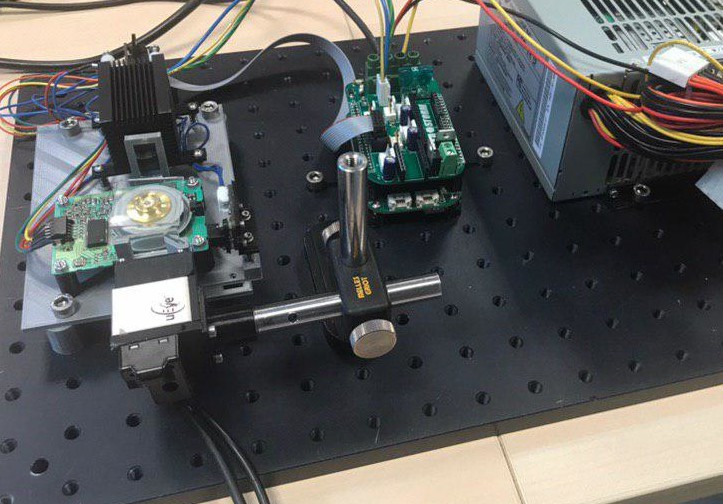
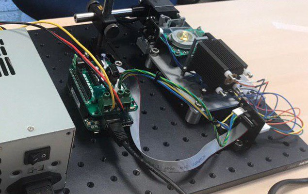
The scan head passes all tests; laser can be turned on, polygon rotates and the photo diode can be read out via the circuit.![]()
![]()
-
Hexastorm featured at Fabbaloo and trending on Hacker News
08/05/2019 at 11:17 • 0 comments -
Assembled boards
07/31/2019 at 12:27 • 0 commentsI have assembled the boards. The results are shown below;
front main board of laser module
![]()
back main board of laser module, the laser diode requires a heat sink (which is not shown)
![]()
front cape of beaglebone
![]()
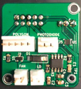
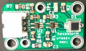
front photo-diode board (photodiode in the wrong position bar should be right... not left)![]()
-
Updated Boards
07/22/2019 at 11:57 • 0 commentsI have made three PCBs; beaglebone cape, laser module pcb, end of stopline pcb.
This should have the following advantages;- Photodiode is read out with amp and Schmith trigger
- Laser scan head can easily be detached from machine
- Electrical wiring to the laser are kept short. The anode and kathode of the laserdiode are not exposed outside of the scan head. Damage is prevented and electrical noise minimized.
- The scanhead is a separate entity from the cape. The scanhead could be interfaced by other boards. The scanhead can also be detached to place it into a different setup.
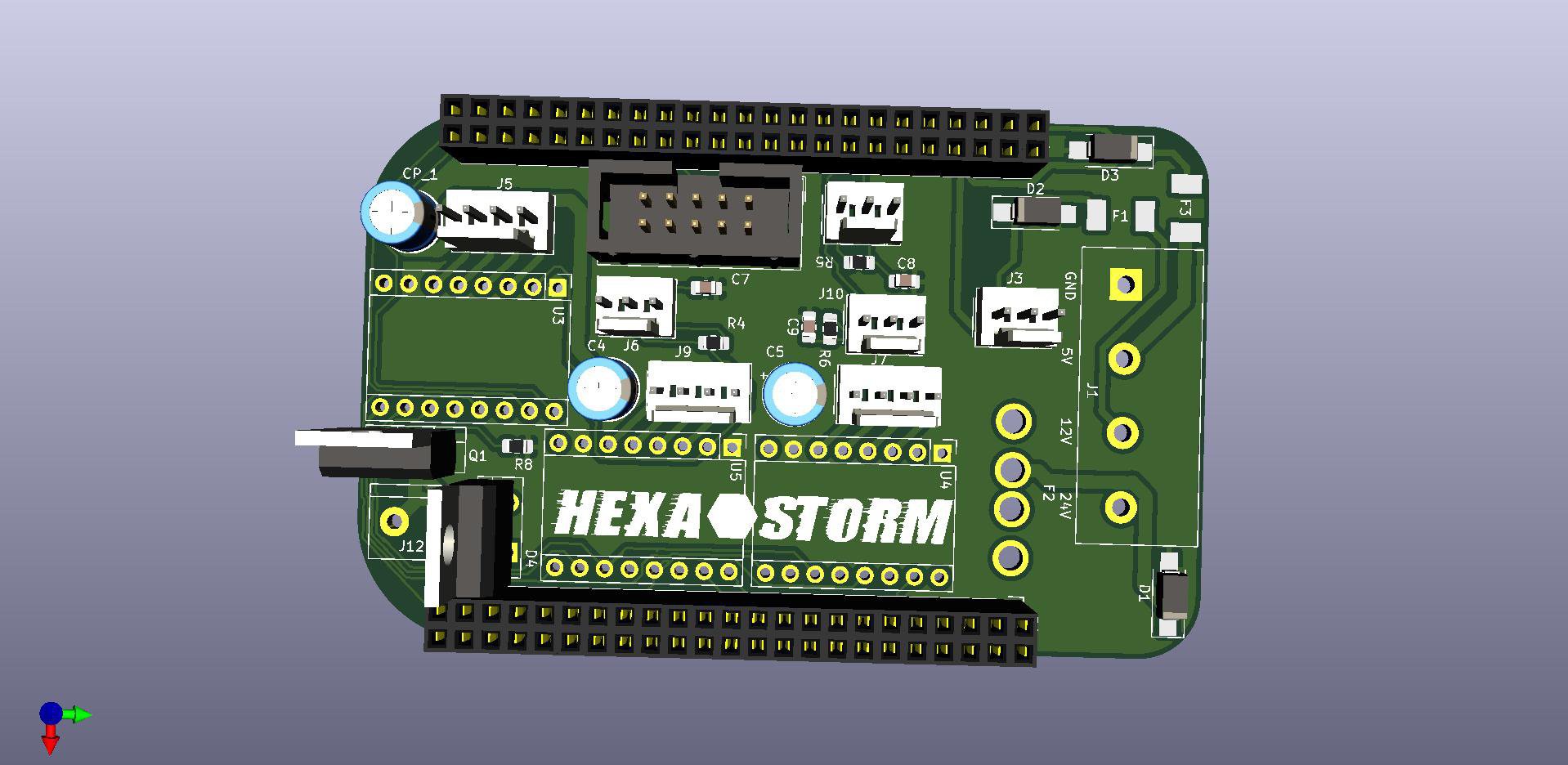
The Beaglebone cape is shown below. The main board can be connected to three stepper boards, three endstops, the spindle controller and the scanhead via a 10 pin cable.
![]()
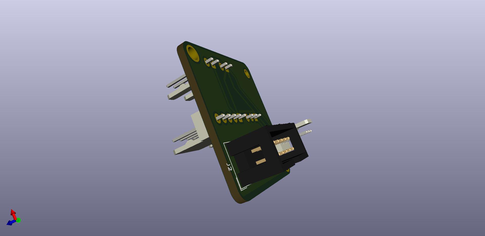
The Beaglebone cape talks to the scanhead via 10 pins. The scanhead also needs three power lines. The power is provided via the Firestarter cape as there are some safety measures present there.
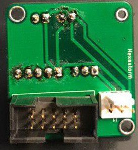
The scanhead board has two sides in and out, so one can connect to the components in the scan head.
![]()
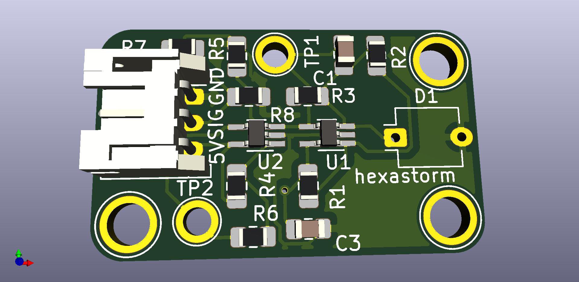
The PCB for the for the photo-diode with the op amp and the Schmitt trigger is shown below![]()
Boards are submitted for order via PCB way. Total costs for 3x 5 boards plus shipping is 38 dollars. -
Printing with droplets
07/16/2019 at 12:45 • 0 commentsLet's quickly read, Inkjet Technolgy for Digital Fabrication, IAN M. Hutchings. There are various ways to create droplets such as Continuous Inkjet and Drop On Demand (DOD).
A well known challenge with DOD technologies are the limits with respect to viscosity. Continuous inkjet allows for higher viscosity but the stream has to be broken up into droplets and droplets need to be selected.
In Continuous Inkjet generation an electric field can be used to position the droplets, see Sweet 1965.
Rejected droplets can be put in a container and reused.
This requires a conductive ink. For non-conductive inks, Kodak has explored alternative selection techniques to select the droplets via air. A patent on droplet selection can be found here US8544974.
The liquid stream has to be forced to break up into droplets when the liquid stream leaves the nozzle. As man, you might recall from peeing that the stream doesn't break up into droplets immediately when the liquid leaves the nozzle.
A way for doing this is via a piezoelectric effect or heating. The droplets can be detected by a stroboscope and a camera.
I claim that the Hexastorm is used to force the break up of droplets in a continuous inkjet head using heating. I claim that the Hexastorm is used to detect the position of one or more droplets.
I then claim that the Hexastorm is used as a selection mechanism to evaporate certain droplets or push them away by colliding them with another droplet generated with laser induced forward transfer.
I claim that the Hexastorm is used to emit a droplet from one stream via LIFT and then merge it into another droplet.
Likewise, I claim the same things for a drop on demand system where droplets are ejected by acoustic energy, piezoelectric effect or thermal effect. Again the Hexastorm can be used to detect the position of droplets, see if nozzles are clogged and calibrate the inkjet head by checking the position of droplets either upon the substrate or in the air.
Light can be used to cure liquids so they become conductive via so called flash curing. In some novel conductive inks nano-particles are dissolved. The solvent is used to lower the viscosity and facilitate transportation in the head. If the ink is on the substrate, the solvent must be removed which is done via flash curing.
They could also cure UV inks and vary the dosage per ink using optical coherence tomography. Or use OCT to check wether the conductive ink is fully cured. This could be very interesting for companies like Luxexcel. They try to create optical components with droplets, see patent application EP2412767A1.Anyway, what might be of interest to the reader is the work of Georg von Hippel from the MIT Sloan school of Management.
At the moment, l I am a bit done with creating prior art and will move back to building the scanner!
People who think I am over doing it with the claims should read about the patent war between formlabs and DWS. Basically, DWS patented the idea of heating a liquid in a bottom up projection photo-polymer printer. I agree with Formlabs this is not novel at all but also agree with DWS that this is a typical 3D printing patent. Stratasys has a very similar patent on a heating build chamber for fused filament printers.
-
Generating prior art with patents
07/15/2019 at 18:21 • 0 commentsPrior art is of huge importance to the open-hardware movement. It prevents that certain markets become locked for 20 years by patent law.
Let's generate some prior art with patents. I claim all the claims generated by rewriting all patents in the world which use the concept of scanning mirror and do not mention the concept of scanning prism. I make these claims by rewriting the scanning mirror patent but now using the concept of scanning prism. I think these new claims would be obvious for a Person Having Ordinary Skill in the Art (PHOSITA), familiar with my work and familiar with the patent. The total of these claims and other prior art describe the legal application limits of transparent polygon scanning.
Let's provide some examples;
Example 1: US7892474
This is an interesting patent it describes something like Continuous 3D printing. Could explain why Carbon didn't outline the figure 3 option.
Claim 1 reads "... comprising the step of solidifying a photo-polymerizable material by means of mask exposure of a build area or partial build area in a building plane via electromagnetic radiation from a digital light processing/digital micromirror device projection system ..."using transparent prism creates prior art not under patent let's reformulate
"... comprising the step of solidifying a photo-polymerizable material by means of refraction exposure of a build area or partial build area in a building plane via electromagnetic radiation from a transparent polygon scanner device projection system ..."
Example 2: US9079355B2
The first reflective polygon scanner in photo-polymerization was described by the Institute of Physical and Chemical Research (RIKEN) in 1997.
RIKEN did, however, not describe the combination of a laser diode and reflective polygon scanner.
Shuji Nakamura of Nichia discribed the blue diode laser in 1996. Envisitontec patented the combination of polygon scanner, laser diode and 3D printing in 2011. This was a smart legal move.Claim 1 reads:
"... and deactivatable ultraviolet laser diode and a rotating polygonal mirror ..."
using transparent prism creates prior art not under patent let's reformulate
" ... and deactivatable ultraviolet laser diode and a tranparent polygon scanner ..."
Example 3: EP3233499B1
Laser induced forward transfer can be used to generate droplets with laser light. The earliest description I could find date back to 2004.
Poeitis patented this process for bio-printing in 2015. In this video, it is describes how laser-assisted bioprinting works. The process is also shown in figure 1 and 2 of the patent.
From the video it can be concluded that a transparent polygon scanner can be used to shoot with a laser pulse on a disk so a droplet is emitted. This can be used in bioprinting, 3D printing or used in the semiconductor industry to deposit resist, glue, polymer or ink etc.
A microfluidic chips with multiple channels could be made and the transparent polygon could be used to send a laser pulse to the disk and select the channel from which the droplet is emitted.Example 4: US900887
Compact, low dispersion, and low aberration optics scanning system. I claim the same in this patent but then with a moving transparent prism.
Example 5: US6850363
Arthur Ashkin, nobel laureate, invented the optical tweezer with Gerard Monrou and Donna Strickland.
This patent describes optical tweezer in a laser scanning microscope using a scanning mirror. I claim an optical tweezer made by a scanning transparent prism or galvo transparent prism. -
Glass tubes and laser scanning
07/13/2019 at 10:09 • 0 commentsUV Light can be used to disinfect the material flowing in tubes. Infrared laser light can be used to heat specific particles/cells/droplets if the tube is made from glass. Here is a market report on UV disinfection equipment. A company active in UV disinfection is uvo3. Transparent polygon scanning can be used in vibrometery, which can be used to measure fluid flows in glass tubes using laser doppler velocimetry. Laser galvo scanning interferometry can be used for flow velocity measurements through disturbing interfaces. Likewise a transparent polygon scanner can be used to measure flow in chemical processes.
Ideally, the glass tube is square to minimize a lensing effect.
Furthermore, an interesting option would to polymerize particles in the tube, or sintering takes place in the tube. MIT patented this process in US7709554, but used a DMD projector and not a transparent polygon scanner. In addition, I claim the case the walls of the tube are created from Teflon AF. This could for instance done on a micro-fluidic chip which would again be produced by a transparent polygon scanner. One could simply use the setup outlined here and use a transparent polygon instead of a galvo scanner. If this is not sufficient I would make the tube square and sufficient porous by laser engraving the tube with a transparent polygon scanner and C02 laser, where i spin the prism at a relatively low speed and possibly use an auxiliary bundle to fix the timing.
The speckle pattern can be measured which is created by shining in the tube. This process can for example be is used in the food industry to measure the dairy viscosity in a glass tube. You could walk around in the garden with a handheld Hexastorm and measure the biological status of a plant.
The detector could be a CCD/CMOS camera at the same side or opposite side of the plant leaf or glass tube. Possibly, the transparent polygon scanner is under an angle so the reflected light does not fully transmit back to the polygon scanner but can be measured by another device at the same edge of the tube, like a CMOS/CCD chip/grating light valve with appropriate lens.The laser is pulsed and the time of flight is measured. This allows one to both record the amplitude and time phase spectrum of the material under measurement. Incidentally, I claim that gasses are flowing in the tubes or that that tracers are applied to the particles in the tube.
-
3D Glasses
07/12/2019 at 18:31 • 0 commentsIn my previous post, I outlined how a transparent polygon scanner can be used for detecting eye diseases.
Logically, a transparent polygon scanner can also be used in 3D glasses. Reflective polygon scanners are used for creating a screen in a laser TV. A scanning prism can also be used to create a Laser TV; especially if the configuration is used as described in the wide scan angle log..
A lot of companies are active in 3D glasses; e.g. Google Glass, Magic Leap, Oculus and Hololens.
Colors are created in a laser TV by coupling three lasers of different wavelength and optical power in the same bundle.
For 1080p at 100 hertz. you would like something on the order of 100,000 lines per second.
At 30.000 RPM and 8 sides prism you have 4000 lines per second.
This is not enough;
Option 1: Miniaturization
Scale down the size of the prism, this will make it easier to spin it at high speed. The angular momentum drops due to lower mass and radius, which implies lower energies at a fixed RPM. The fastest spinning disk ever made at 600 million RPM is also small.Option 2: Fiber array
You could use 20 fibers where each fiber has 3 lasers but once you have multiple lasers per color, then you have to get everything very precisely aligned with 6 degrees of freedom. This is a tough problem with just 3 colors. Let alone 20 fibers with 3 laser colors.Option 3: Increase the number of facets
There are prism which have 72 facets and can be spun at 70.000 rpm (see roadrunner).Option 4: Optical transformation
Project 1920x1080x100 pixels but divide it over 4000 lines where each line has 51840 pixels. This would however require a small spot for a 20 mm long line of something like 385 nm which seems unfeasibleIn summary, the problem seems quite hard. A polygon would be needed that can be spun at say <200000 rpm. The second in the other direction can then be created by a second prism.
Still there are many companies that believe in this see Scanning Mirror Devices Patent by Apple Computers.
I claim everything Apple claims; with the fancy pictures and all... major difference; using a scanning prism!
 Hexastorm
 The germanium prism is shown