-
Electrical Redesign
12/27/2018 at 14:58 • 0 commentsThe Firestarter PCB was designed in Altium. For the new design, I plan to use Kicad, for progress see Github.
It will consist out of two boards; a main board on the Beaglebone with three stepper drivers and a control board to drive the laser diode and measure the photodiode voltage.
In the original design, I used a voltage divider to measure the photodiode voltage. The resistor was chosen with the Axel benz formula. A resistance of 340 kOhm works.
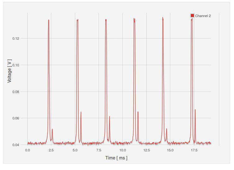
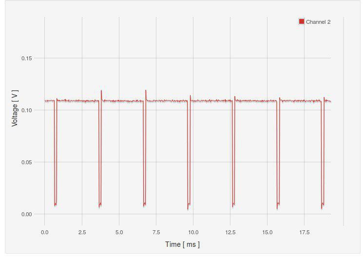
However, a photodiode is something different than a photoresistor. Electronic designer recommended to use the "proven" method. Use an op-amp to read out the voltage. Subsequently, use a Schmitt trigger to get a block pulse. This was also used by H zeller in Ldgraphy.
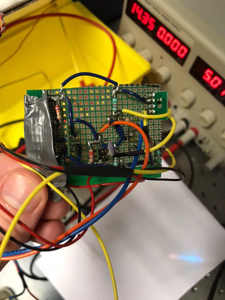
I build the circuit and got it to work with 220 picofarad for C1, see circuit.
The signal is still sensitive to stray light, so use a cap around the photodiode. The photodiode must be placed closely to the rotating prism to fetch all facets.
Circuit:![]() Signal at TP5/ vphoto in design.
Signal at TP5/ vphoto in design.![]() Signal at hsync in design.
Signal at hsync in design.![]()
-
Optical Redesign Final
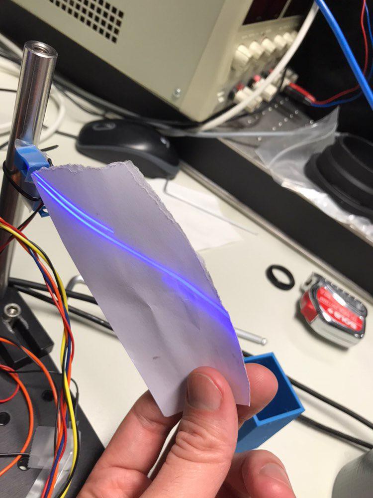
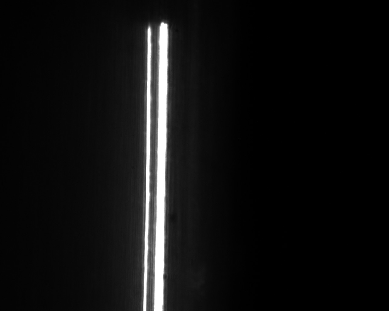
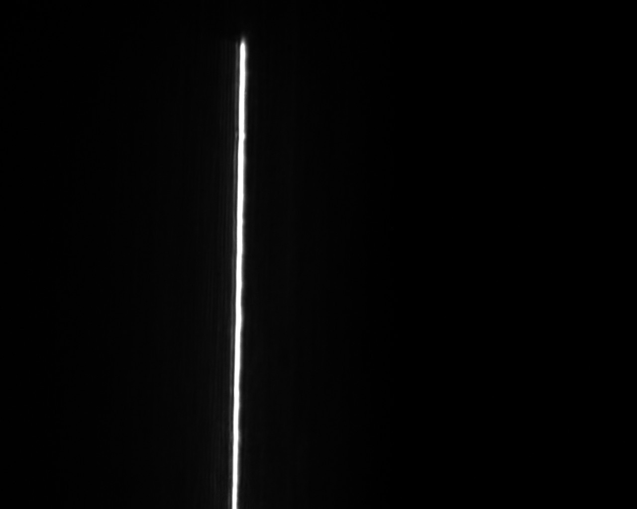
12/18/2018 at 10:45 • 0 commentsI tested the new design with the 75 mm and 25 mm cylinder lens. The spot size is around 24 micrometers and circular. The line thickness is 63 micrometers. This can be seen from the picture. The pixel size is 4.8 micron. The line is around 13 pixels wide. The cross scan error is in the order of 40 micrometers. This is an enormous improvement as compared to the first version; which had a line thickness of 260 micrometers.
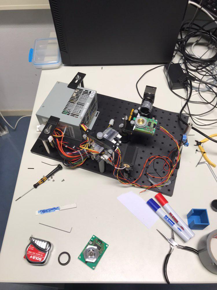
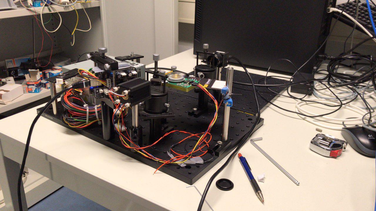
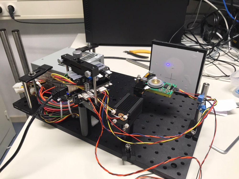
![]() The setup is shown below;
The setup is shown below;![]()
-
Optical Redesign; First tests
12/13/2018 at 23:33 • 0 commentsAs stated earlier, I did a test where I added two cylinder planoconvex lenses; one with 250 mm and the other with 75 mm focal length. The spot was 40 micrometers in diameter and circular. The cross-scan-error is reduced but not removed. The line width is 140 micrometers.
Hereafter I removed the lenses and focused the laser directly with the aspheric lens right after the polygon. The distance to facet of the camera chip was in the order of 30 mm. The line is then 260 micrometers wide.
As I did not have short focal length cylinder lenses in stock, I proceeded with a 25 mm and a 8 mm camera lens and measured the vertical component of a by the lens focused coli-mated bundle. The line width was 101 micrometers and 73.6 micrometers.
Combing all the results;
the apsherical lens pair reduces the cross scan error
the apsherical lens pair improves the spot; more circular and better quality
the focal length of the second aspherical lens has to be as short as possibleA short focal length would require that the polygon is oriented vertically. The path is not long enough for a mirror. I did a test and the polygon seems to operate fine vertically and even upside facing down.
Furthermore, I measured how planar the prism is. The prism is planar within 5 micrometers.
Still there seem to be significant offsets. I therefore assume that when the air bearing gets into balance; it achieves an equilibrium where the polygon is tilted. This seems to be filtered out by the second asherical lens. An other source for error is the 5 arc minute tolerance on parallel opposing faces.
This is not removed by the cylindrical lens and that is why its focal length has to be kept as short as possible.
Pictures:
Camera with lens imaging a colimated bundle.S
![]()
Lines visible further away from the prism of the invidual facets.![]()
Setup with cylinders.![]()
-
Improved optical design
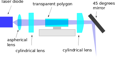
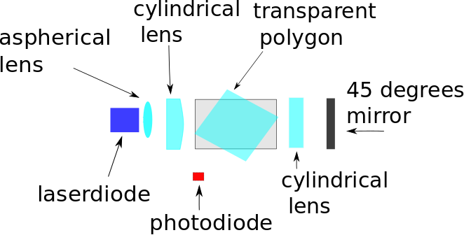
12/02/2018 at 17:31 • 0 commentsThe design I am now aiming for is shown below. The first cylindrical lens has a focal length of 230 mm. the second lens a focal length of 75 mm. This should reduce the cross scan error and make the beam more round.
A side view and top view are shown below. ( the cylinder lenses are drawn incorrectly the curved side should face the bundle)
![]()
![]()
Note, this is different than the technique used in reflective polygon scanners where the collimated bundle is compressed to a line and after reflection is expanded to an ellipse, see patent.
-
New photodiode position
11/27/2018 at 23:38 • 0 commentsAt the moment, I am trying to minimize the cross scan error and improve the resolution.
My work has allowed me to build as setup, so I can improve the optics.
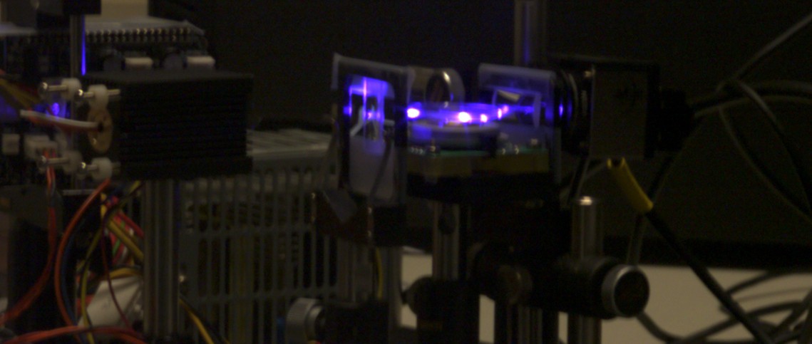
So far I have figured out that I can change the diode position. At the edges, the reflection is about 40 percent. The spot you see on the screen is the pulse send to the photo-diode. It reflects and transmits at the same time. I plan to use the space created, to add cylindrical lenses.![]()
-
Spot stability
11/19/2018 at 23:21 • 0 commentsIn the past weeks, I did the following two measurements;
1. Polygon disabled
Vibrations caused by the rotating fan moved the laser spot in the order of 50 micrometers.
With a disabled fan the laser spot moves in the order of 4 microns.2. Polygon Enabled
I adapted the firmware so I can use only one facet. The laser spot moves at maximum 25 microns over 30 measurements. The exposure strength varies a bit on a facet-per-facet basis. The spot is slightly distorted due to the scanning; 37 micrometers x 77 micrometers. The spot size also varies per facet; some spots measured ; 34 x 110 micrometers.
-
Polygon scanner cross-scan (wobble) error
11/05/2018 at 23:16 • 0 commentsA crucial feature is that the resolution of the scanner should be better than 100 micrometers. I measured the prism today and the lines generated by different facets do not overlay each other. Although, I thought I had solved this. Luckily a business contact clarified it, link.
I quote;"One of the characteristics of a polygon scanner is cross-scan error which is a deviation perpendicular to the scan line. This is also referred to as wobble or dynamic track error. There is non-repeatable wobble error from the motor bearings. There is also repeatable error from polygon facet to datum error. There is no such thing as a perfect polygon scanner. There is always some wobble error"
Zeller stated that he also had this issue with reflective polygons, see link.
"but also different mirror faces are ever so slightly tilted up/down resulting in a forward/backward movement of the project lines in some mirrors"
There are several ways to mitigate this;
optics
collimate laser bundle with aspherical lens
focus laser into one direction with cylindrical lens
refract through prism
focus laser into other direction with cylindrical lensThis would fix a lot of issues;
- beam is more round
- wobble error is gonesoftware
only use one facet or correct on facet basis
This has several disadvantages;
- cannot reduce non-repeatable motor bearing errors
- speed is clipped, in case of one facetA multi facet exposure is shown below, The different facets are visible.
![]()
This is fixed in the software by enabling only one out of four facets.![]()
-
First exposure
10/29/2018 at 23:15 • 2 commentsSucceeded in making my first exposure today. At the moment, I am working with cyanotype paper. This is pretty cheap, 50-70 eurocent per sheet, and easy to develop with water.
The dosage was not optimized. The polygon speed was 2400 RPM. The laser driver was set at 50% of max power. Each line was exposed 10 times, so the speed of the scan head was something like 0.2 mm per second. The line speed of the scanner was 1 m/s. The laser frequency is 400.000 Hz.
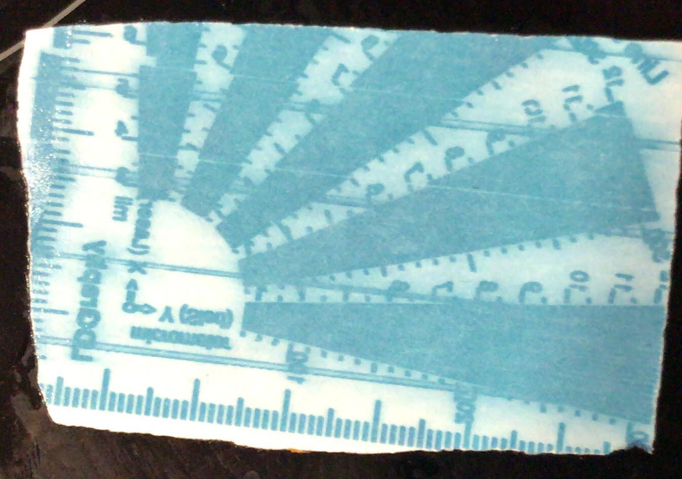
Besides the not perfect dosage, there are several other issues. The laser goes through and over the prism. So lines are visible in the end result. The text in the final image is flipped,![]()
-
Prism alignment
04/26/2018 at 11:27 • 0 commentsI recently received a question in my mail on the alignment of the prism. When i made the technical presentation, I did not know how to align the prisms. I have improved the mounting procedure. Basically what i do is, i take the top of with a Dremel ( a drilling machine). I can then remove the reflective polygon. At the center of the reflective polygon there is an axis. With my Dremel I grind this axis away until i have a small hole at the center of the top plateau of the polygon basis. I put a bit of UV glue in the hole i created and place the prism on top. Then by rotating the prism with respect to a reference point I am able to center it. I then use a UV flash light to fix the prism. Afterwards, I measure how planar the prism is with a displacement meter. The current prism is planar within 5 microns. The prism can rotate with speeds up to 10.000 RPM, beyond it become too noisy as it is unbalanced.
-
firestarter pcb
04/25/2018 at 22:34 • 0 commentsI used an FPGA in my original design but it has proven to be complicated and expensive. The Xula LX25 is well documented but produced in low volume and seems to be no longer for sale.
Luckily, Henner Zeller made a polygon laser scanner, the LDgraphy, with a beagle bone black / green. With the LDgraphy firmware a laser scanner can have a clock speed of 2.7 MHz. This is more than sufficient for a transparent polygon scanner. I looked at Zeller's code and it is actually very accessible. With a couple of minor changes it should be suited for the Hexastorm.
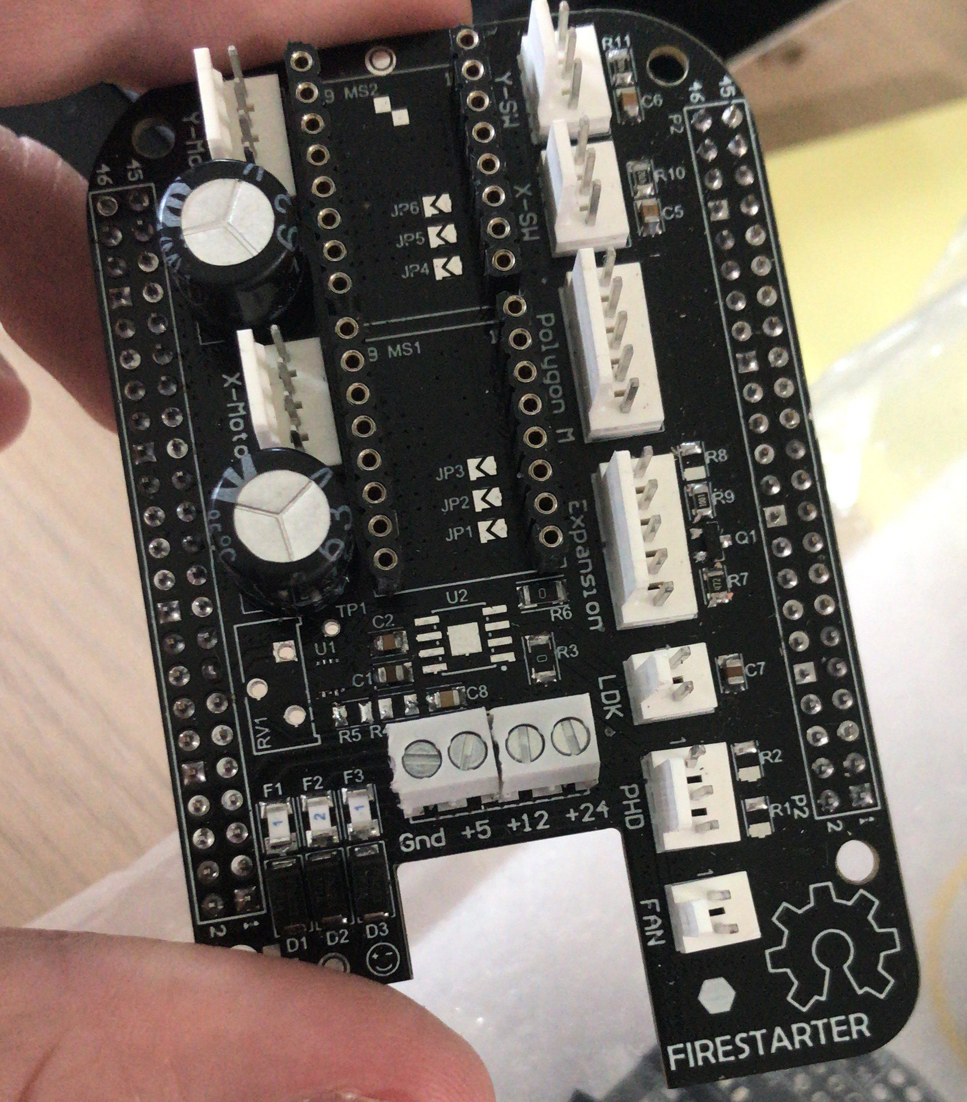
I also had the luck of finding an electrical engineer, Salvatore Puglisi, who could design me a board. Result is below see figure 1. I have added the schematics of the board as pdf to the project repository, see firestarter.pdf. I also added the gerber files in a zip.
I use a simple voltage divider to detect the signal of the photodiode. This worked with the Xula LX25.
Zeller uses a Schmitt-Trigger to have a clean signal for the BeagleBone. I already tested the firestarter board and this is not needed.
Zeller also didn't mount the laser driver on the cape and made his own laser diode driver.
I decided to go for the IC-HKB from IC-haus. It is not seen in the picture and needs to be mounted on the board at U2. Maybe in a future version, I will make one PCB per laser scan head and one central board with stepper drivers.![]()
 Hexastorm
 Signal at TP5/ vphoto in
  Signal at hsync in
 The setup is shown below;