-
Laser Prism Scanner Summary
04/12/2023 at 12:51 • 0 commentsI made a summary video of my laser prism scanner work.
This should save you time if you are interested in the topic.0:00 - Intro
1:35 - Process
2:58 - Applications
5:00 - Optics: prism more accurate than mirrors
5:59 - Optics: displacements caused by prisms
7:44 - Optics: rotating polygon mirrors vs rotating prisms
10:45 - Optics: position photodiode
11:59 - Optics: advanced prism designs
13:16 - Aberrations: how measurements are made
14:23 - Aberrations: cross scan error versus jitter
16:08 - Aberrations: mounting
16:56 - Aberrations: solutions to mounting
18:44 - Aberrations: prism imperfections
20:09 - Aberrations: solutions to scan errors
21:18 - Aberrations: vibrations
22:34 - Aberrations: prism mounting using Ricoh motor
24:04 - Aberrations: new mounting solution
26:04 - Aberrations: new mounting solution (Freecad view)
26:57 - Aberrations: measurement cross scan errors
29:07 - Validation, result of exposures
29:59 - Positive feedback
31:20 - Negative feedback
33:48 - Outlook
35:08 - Origins laser prism scanning
37:08 - Challenges with thick laser prism scanners -
A reply to "The state of open-source in 3D printing in 2023"
04/04/2023 at 08:18 • 0 commentsIn the blog state of open source, Prusa complains about cheap 1:1 clones who do not honor the open source ethos and as remedy suggests altering the license.
The most successful companies, e.g. Microsoft and Apple, in the world are closed source.
Still closed source seems not to work for a number of technologies; operating systems (Linux) and programming languages (Python).
In the nature of the firm, Coase argues that the main reason to establish a firm is to avoid some of the transaction costs of using the price mechanism.![]() Open source lowers the transaction costs for inbound innovation. Information is more readily available to outsiders and less asymmetric. As a result, the technology grows.
Open source lowers the transaction costs for inbound innovation. Information is more readily available to outsiders and less asymmetric. As a result, the technology grows.
I think open-source is best suited for "highly" complex products with an initial weak product market fit. It works better for software than hardware. As hardware is harder to reproduce. This leaves the question of monetization.
Open source software is now monetized by cloud providers who earn money by running it in the cloud.
Examples are Github, Amazon Web Services or DataBricks.
It is also monetized by software developers who tailor the software for specific business needs.
They enjoy large benefits by the fact it is open source. As they can simple hop companies and sell the same knowledge again. A problem with proprietary software is that the new firm or client of the developer would also require a license.In your blog you also give an example of solar panels. One example for all is solar panels – the original inventions and processes were gradually copied by Chinese companies. After that, with the help of state subsidies and tax breaks, they drove all competition out of the market within a few years. Today, you have virtually no chance of buying a non-Chinese-made solar panel.
I agree with your assessment that this makes solar panel manufacturing less profitable. It might also be a reason for a government to intervene using tariffs.
Still, an entrepreneur can still make money. Once the solar panel becomes free, the challenges becomes getting it on your roof. You might also need advice on how to best place your solar panel. It is very hard for the Chinese to compete with a Dutch solar installation company given the fact they are in China.
They can also not work in the Netherlands due to regulations. If China makes printers for free, you might need to alter your workforce or firm. I still see a lot of ways of making money.
Moving back to the Prusa firm. I would not alter your open source approach but better look at how it can provide unique value. Your company actually pursues a mixed strategy. Part is closed and part is open.
It is impossible to make a firm a completely "open". I would not focus on changing the relation between Europe and China or the patent system. These things are external to your company and not under your control.
You can make it easier for external parties to add new tools to your printer.
You could give these external parties a slice of the profit. Goal here is to really think outside of the box and look at your relation with the customer.
As example, there is a Dutch company called Swapfiets, who offers bikes via a subscription service instead of selling them. This has been hugely successful. I would not advice you to offer a subscription service. Still, it shows that the way you interact with the external parties can be a key differentiator.
If you control the most popular design of the printer, you should still be able to make money simply as you decide which parts end up in the next printer.
A successful open source approach, requires more thought than simply putting the source code on the web.
This was done by Lulzbot and not successful.Finally, I partly disagree with your view on patents.
I believe like you and the Economist that the patent system is broken. From experience, I believe that most patent applications are a failure.
Still, you should patent given the opportunity. If you have a lot of money, understand the boundaries of your innovation, have a good patent able innovation; you should patent. A patent might also be key in getting government support.
In your case, you might not want to use your name as it destroys your image.
You could still use a shell company and someone else his/her name. Some companies hide patents so they can strike their opponent by surprise. I currently lack the resources to do it.
Filing patents is also very tricky.
Still, I don't see how not patenting helps the world if you really see a good opportunity. If you want to change it, complain about it, use the power you have in a way which aligns with your views, but don't leave money or power on the table. -
Cross scan error measurements new bearing
04/01/2023 at 19:29 • 0 commentsI will add a presentation to clarify,
I reduced the pole length to 10 mm. I now end up with a cross scan error of 180 microns (60 pixels at 3 microns wide). The pattern is very constant over time and seems to be due to the prism.
I measured seven prisms and arrived at an error ranging from 35 pixels to 45 pixels.
The prism in this image had an error of 41 pixels. As a result, I think 19 pixels are due to "vibrations".The camera distance to the prism is 36 mm (prism facet parallel to CCD chip and distance between prism and CCD chip). Note that this is very similar to my earlier measurement with the Ricoh motor (PCB motors suited for laser scanning). Here I arrived at 160 microns.
![]()
-
End loaded cantilever beams (updated)
03/30/2023 at 09:30 • 0 commentsI did experiments with the new bearing.
Results so far;
- rotation can be achieved vertically;
ferrite is added below the PCB. The magnets in the rotor are pulled toward the ferrite
As such, the rotation axis does not have to be parallel with gravity.
The motor is more than powerful enough to overcome the additional friction.- on small time scales, i.e. less than 10 facets/lines, the cross scan error is low on longer time scales ,
i.e more than 30 facets. The cross scan error is high.
For small time scales, the cross scan error seems good enough for exposure.An image at a short time scale, i.e. less than 10 lines in image.
![]()
An image of a long time scale,
![]()
The spot on the side is as not all light is refracted through the prism or due to some internal reflection.
This is easy to fix by either a slit or changing the thickness of the prism. As such it is disregarded.
From additional research, I conclude that you are indeed looking at a vibration. This vibration is likely due to particles or dusts between the axis and the bearing.
I shortened the pole and still saw this behavior (see next blog). The noise removed after adding a bit lubricant.
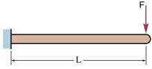
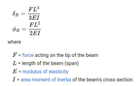
I also expect that part of the error can be explained via an end-loaded cantilever beam:![]() This displacement and angular deflection are described by the following formula;
This displacement and angular deflection are described by the following formula;The centripetal force rises with the square of the speed. As such, I have two methods to test this theorem;
- reduce the speed
- decrease the beam length
Calculating the first natural frequency of the beam and see if this is in the time domain of 30 lines.
I arrived at multiple kHz. Probably, the treatment is too simple.
Experimental notes:
Speed around 1000-2000 RPM
Length extracted is 13.75 mm
Length used in this experiment 18.8 mm -
Mounting prism
03/13/2023 at 16:40 • 2 commentsI came up with a strategy to mount the rod onto the prism.
A very viscous putty is placed between the rod and the prism which becomes very hard and green.
The rod hole tolerance is low and the prism rotates over its glass substrate.
You might argue that some of the putty sticks out and this affects the rotation. I cut a small groove in the final version.
Friction seems low,
I will need to check measurements for the cross scan error.
Most interesting would be to compare distorting coming from the prism facets with those coming from the bearing.
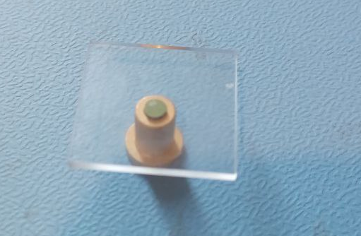
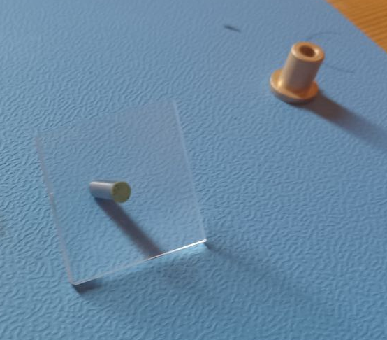
In the figure below you see a quartz prism, a sinter bronze sliding bearing and green puttyIn the figure below you see parts separated;
Curing time is around an hour at 50 degrees. The vendor recommends not going over 40 degrees.
-
Dispersive Rotating Prism Spectrometer
03/10/2023 at 09:52 • 0 comments
The aim of this blog is to create prior art for a dispersive rotating prism spectrometer.My inspiration here comes from Jerry de Vos. Jerry de Vos is working on a plastic scanner. This project aims to develop a simple handheld scanner that can detect five different types of plastic.
At its core, it contains a photodiode and 8 leds emmiting specific wavelengths2 of near-infrared light. By flashing each LED individually onto a plastic sample and measuring it's reflectance with the photodiode, we obtain its (discrete) reflectance spectra.
Like Hackaday, I am sceptical of the project. Jerry has been able to reach a large audience.Let's look at a dispersive infrared spectrometer:
![Spectrometer component diagram]()
Broadly speaking, all optical spectrometers consist of an entrance slit (1), a diffraction grating or prism (2), a detector (3), and routing optics (4). The entrance slit allows light into the spectrometer, where a system of mirrors or lenses routes it first onto a diffraction grating or prism, and then onto the detector. The grating or prism splits the light into its constituent wavelength components, and the detector records the light intensity as a function of wavelength. If the spectrometer has a large spectral range, it may also have filters to stop higher order light from reaching the sensor (source).
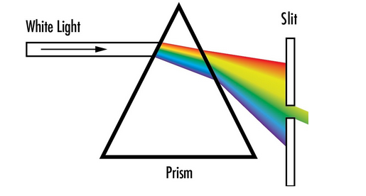
A prism where opposing sides are not parallel refracts lights as follows. Key here is that each wavelength is refracted differently, due to dispersion.
So far I have used prism with an even number of sides. Prisms with an odd number of sides are
typically more disperse and deemed undesired for my application.I am not aware of a dispersive spectrometer where the prism is rotated.
As such, I claim a device used for spectrometry where the prism has uneven sides and is rotated.
As application domain, I claim all the uses of spectrometers prior to march 10 2023.
As shown on this blog, I claim the prism is rotated using a PCB motor or BLDC motor.
Furthermore, I claim the position of the prism is tracked using hall sensors and or optically via a laser or led.
The laser is incident onto the prism on any from the sides. Its reflection is captured by a photo diode and used to monitor the position the prism is in.
Light is shined onto the sample by an external source. Preferably this has a broad spectrum and uniform angle of incidence. The spectrum and the angle of incidence need to be known. One could collimate the light source or use multiple light sources.
A slit or lens might be used to get the light into the spectrometer and ensure a certain angle of incidence.
A slit might further be used to narrow the detection by the detector, used to detect the incident light.There are a couple of nice things of this technique. The prism can be made really small. Prisms of 1 mm size exist.
The prism could also have three unequal angles so that each sides works slightly different.
There are a lot of complexities; rotating the prism, developing an algorithm to collect the data and making it cheap.
These have been solved by the open hardware laser prism scanner project. -
pcb windings, mini laser prism scanner and magnetic levitation
02/28/2023 at 21:57 • 2 commentsI got two tips from readers.
Please note that my current focus is construction of the bearing.
Different PCB windings;
The advantages of improving the PCB windings are;
- ability to replace rare earth magnets (neodium) with ferrite magnets
ferrite magnets are 2 or 3 x times less powerful but much cheaper
- it might be possible to go from a four layer PCB back to a 2 layer pcb (reducing costs)
- ability to achieve higher spinning speedsKeith reinolds pointed out that a Faulhaber winding is more efficient than the bugeja coils or the improvement outlined by atomic14.
This is outlined here.
A linkt to a review paper is provided by gravis https://ietresearch.onlinelibrary.wiley.com/doi/full/10.1049/iet-epa.2020.0141Mini laser prism scanner
It could be useful to make a very small laser prism scanner. There are applications in imaging, communication etc. as outlined earlier.
Two things are of interest;
You can buy precise micro prisms, which have dimensions around 1 mm.
https://www.neg.co.jp/en/assets/file/product/ep/micro-prism.pdf
Magnetic levitation
Wikipedia provides a good overview on magnetic leviation.
You might be able rotate the prism if it is made from a diamagnetic material.
Lawrence kincheloe pointed me to an article which does this for a pyrolyte sheet,
https://pubs.acs.org/doi/10.1021/ja310365kI can also imagine you trap a rotating prism with a magnetic trap
-
LASER scanner with PCB motor
02/16/2023 at 11:33 • 1 commentDemo of the first working laser scanner in the world which uses a PCB motor.
It's a simple demo. Nothing is made, only a static pattern is generated. It combines a lot of effort by the community and me :-). Next is building the bearing.
-
simple laser vs laser prism scanner for interlayer bonding
02/15/2023 at 08:42 • 0 commentsGravis, I made a blog for your question.
Your question:
I do ponder the rationale for heating only part of the filament. However, it might be just as easy to use a tiny linear actuator to adjust the laser position than use a rotating lens to change the beam path.
My answer:
If you apply too much heat to the previous layer, the structure could collapse.
Even more heat and it could burn or a reaction will take place.
I guess to keep the structure intact, Stratasys does not expose the edges.
For first experiments I would not even use a linear motor but just make straight tracks and pre-expose them with a fixed laser. A laser with a tiny linear actuator is indeed much easier to make.A laser prism scanner is able to expose the previous layer with a much smaller bundle.
I expect they now use a bundle diameter of 180 micrometers for a nozzle of 300 microns. (0.6*300 microns).I think a laser prism scanner has two advantages;
- if you swap nozzle you don't have to change focus of the LASER.
For a 1 mm wide nozzle your bundle width would have to be 0.6*1 = 600 microns.
A laser scanner would just project a longer line. Stratasys could solve this by
adding a motor to the laser lens.- a laser prism scanner allows you to apply heat much more precisely due to the smaller laser spot.
Using a laser prism scanner you should be able to go well below 60 microns in bundle diameter.
The exposure is more uniform. In the case of a single spot it is a Gaussian. With a laser scanner
you are able to overlay multiple Gaussians, i.e. spots, and achieve a higher uniformity.
I could imagine you need to ensure only the top of the previous layer is heated. If your molecule
chains have a length smaller than a micron, I think 10 microns deep should be sufficient.
It will depend on how heat is absorbed by the structure, the bundle diameter of the laser and
diverging hereafter. The thermal diffusion coefficient and cooling of the structure with respect
to the air / environment.
When the new layer is added you want the large molecules to mix at the edges and not the
structure to collapse.
You could look at the scattered light using OCT / laser microscope to get an idea of the
temperature of the structure and ensure you r not overheating. -
Increased inter-layer bonding with lasers continued
02/08/2023 at 15:21 • 2 commentsThe increased inter-layer bonding using laser scanners has my attention.
Materialise filed for patent in 2015, WO2016049621A1. It abandoned the application.
Siemens, the owners of Hackaday, filed for (WO2018188757A1), where they take into account correction parameters by looking at the previous layer. It seems not directly related.
There are many more HP, Epson US11498266B2 etc.I view patents as the Sport of Kings. Given my experience, I decided to
create prior art. There are downsides, but less costs upfront.Previously, I outlined that the laser line is orthogonal to the direction of the last extruded line.
A possible challenge, is that the laser line does not cover all possible motions of travel.
It should be obvious for a PHOSITA, that with a single line immediately after the extruder your direction of movement is limited to 180 degrees with an orthogonal scan line.I therefore claim the following;
two laser lines are projected to cover both sides, depending upon the motion one would
heat up after extrusion and the other prior. Or one side would heat up both prior and after
extrusion.In additive manufacturing it is often beneficial, to execute the printing process at an elevated temperature via for example a heated build chamber.
This creates problems as lasers and electric motors function better at a low temperature.I therefore claim the following;
the PCB board which forms the basis of the laser prism scanner is placed on top
of a thermoelectric (TEC) cooler. This cools down the side of the laser and the PCB
motor. It heats up the side which is in contact with the heated build chamber.
Earlier, I outlined that a combination of two cylindrical lenses can be used to reduce the cross scan error distortion and create a circular spot.
It might be beneficial to elongate the laser bundle orthogonal to the scan line.
As this increases the area which is heated, whilst still using one laser or led.I therefore claim the following;
a cylindrical lens or other lens is used after the prism which elongates the laser / led bundle
orthogonal to the prism. This is done to increase the area that is exposed by the optical bundle.One could use a plurality of emitters but I doubt that the heating process has to be so accurate.
It should be noted that the quartz prism and lenses can be made of another plastic material i.e. acrylic given its low absorption in the infrared range.
This has the advantage that costs would drop.As such, I claim the following;
The infrared emitter is a light emitting diode, all optical elements for the scanner are manufactured
using acrylics.The control system would need to use data to optimize the heating process.
I imagine that an infrared sensor or camera is present that collects the light emitted from the heated area.
It might be possible to collect this information in the laser scanner using the laser microscope configuration outlined earlier. The information is than used to optimize the image formed by the laser or led scanner. Epson claimed this in US11498266B2, however it outlines that information of a temperature sensor is used for the nozzle heater.As such, I claim the following;
I claim that a temperature sensor is used with the relation outlined by Epson.
but that this is used to control the settings of the lasers and not the nozzle heater as outlined by
Epson.It might be beneficial to use multiple wavelengths. The extruder could extrude a thermoplastric material in combination with a resin. In these cases, it might be beneficial to combine the infrared laser with a UV laser.
 Hexastorm
 Open source lowers the transaction costs for inbound innovation. Information is more readily available to outsiders and less asymmetric. As a result, the technology grows.



 This displacement and angular deflection are described by the following formula;
 The centripetal force rises with the square of the speed. As such, I have two methods to test this theorem;
 In the figure below you see parts separated;
 Curing time is around an hour at 50 degrees. The vendor recommends not going over 40 degrees.
 So far I have used prism with an even number of sides. Prisms with an odd number of sides are