-
Hoovering magnets
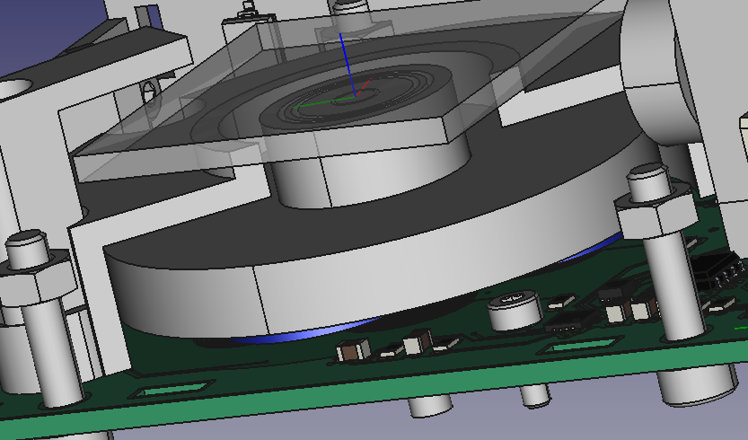
10/25/2022 at 16:06 • 1 commentThe KISS principle is notorious hard to apply. I tried a wide range of solutions to hoover the magnets over the board.
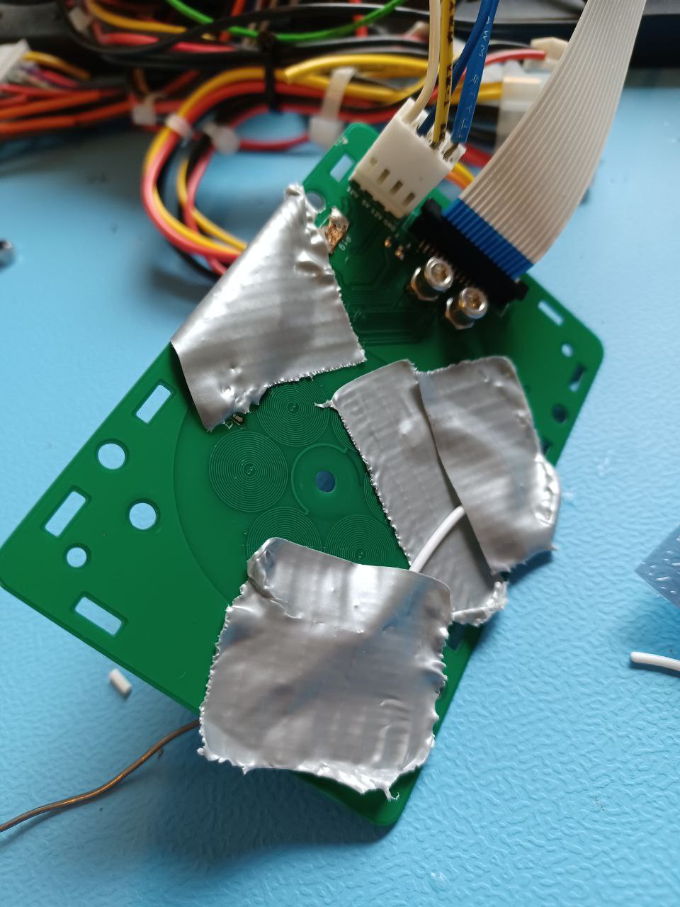
My current solution is much simpler, I use the rotor from the mirror motor as I know this works.
You can see the result belowNext step is to turn on the laser!
-
Changed control algorithm & Repositioned Hall Sensors
10/09/2022 at 13:42 • 5 comments -
Progress Update
09/11/2022 at 16:17 • 0 commentsAbstract;
I made progress on some points but the laser scanning error is still too high
for exposure.
In long:I merged the FPGA code to control the prism motor with the rest of the laser head FPGA code.
The number of LUT required for my design decreased, due to improvements in the tool chain from
Yosys HQ.
Previously, I increased the coil size but had not increased the magnet size. When I increased the magnet size
It became more apparent that I had issues with the Hall sensors. They would jump back states.
The cycle became (CYAN --> RED --> CYAN --> RED --> YELLOW --> RED --> YELLOW --> GREEN etc).
I tried to fix this with the software (failed), then tried stronger sensors (failed) and now moved them away from the center
(improvement, not completely solved / see picture) probably right direction.![]()
The mechanical design also changed.
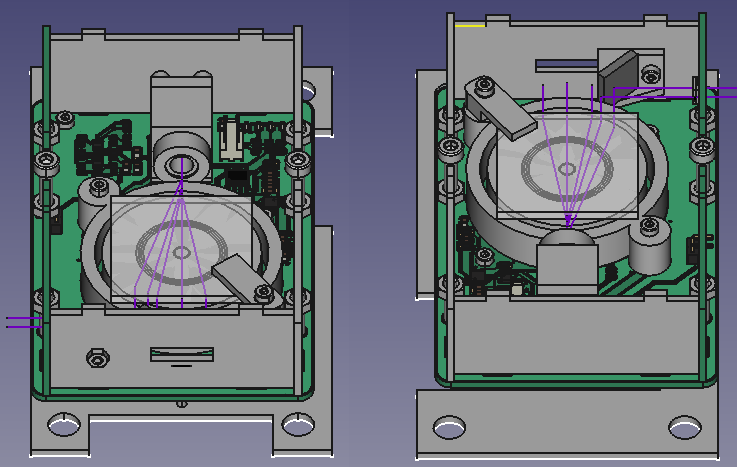
The core idea here is that only the prism rotates and the rest is fixed. As the prism is assumed perfect
Cross scan error is low. So far I found out that the prism can still vibrate vertically, as it is unconstrained.
A further complexity arose that I tried to fix my mechanical design while I was still having issues with the electrical design.
Long story short, it is improving but more challenging than hoped. -
Vertical rotation
07/28/2022 at 17:24 • 0 commentsI am able to rotate the rotor when the PCB is in a vertical position. I did experiments with both magnets and ferrite beads. Both can change the field and disrupt the working of the motor entirely. I found one configuration where ferrite used in each center of the pcb coil and as an outer ring. This led to increased strength. (forgot to write down the article). I also had success with a magnet but it was much harder and I think it is the wrong direction.
I used SS7X4X3W from Toshiba.
I am to improve the mechanical design a bit and then do some optical tests. -
PID controller for PCB motor
07/12/2022 at 14:39 • 0 commentsI made a PID controller for the PCB motor. It is a very simple one. I just check if my speed is below or above the threshold and then adjust the gain by one percent.
-
multi-material
06/29/2022 at 15:46 • 0 commentsThe patent problems of hangprinter convinced me that having a list of wild ideas is key.
Laser induced forward transfer is a process in which droplets can be emitted under the influence of laser light. Typically, a laserhead is moved over a coated glass plate. Due to the influence of laser light droplets are emitted from this plate to a target substrate. For each material the plate is changed.
Let's say I have a prism which can produce different lines for each facet. So in the case of a quadron I can produce four lines. This prism is constructed via the input and output prism method discussed earlier.
These lines would project on a glass sheet where each area is coated with a different material suited for laser induced forward transfer. This material would be on the side of the target substrate. Note that laser induced forward transfer works in both the upward and downward direction. The glass sheet with the coating can be placed above or below the target substrate.The glass substrate needs to move so a new layer can be applied via blade coating and it is replenished. The glass sheet could be a rotating disk and coated in a way similar to the process used by lithoz in the cerafab.
Another option is a rotating cylinder the laser head would then be at the center of the cylinder.
This whole thing would move as a sort of laser induced forward inkjet head over the substrate.
I will add drawings for this contraption. Still it should be obvious for people having ordinary skills in the art.
-
military lidar
06/26/2022 at 16:58 • 0 commentsYou might wonder how I got inspired to alter my prism design so I could elongate the scanline. I was reading up on military applications for laser scanning and found an article on lidar scanning.
I found the following patent application US20190310468A1. The patent is abonded and irvine sensors seems bankrupt.
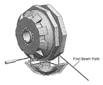
One of the figures is provided below,![]()
Let's first look into the problem they are trying to solve. They try to improve the duty cycle of lidar. A laser bundle has a finite size and gets clipped at the edges.
So by alternating between two reflective polygons they can fix it. This is key in certain mission-critical LIDAR applications such as airborne collision avoidance, military reconnaissance or autonomous automotive applications.This system also has a sort of rotating input mirror for incoming beams. These get reflected and redirected to two reflective polygon mirrors, which are optimized for the outgoing lasers.
The system seems to me hard to align and make.Anyhow, this inspired me to think in terms of input and output prisms. For prisms the outside redirection is not needed. This simplifies it greatly.
You could do it internally.
I will add some ideas for lidar at a later point
-
creating long scanlines
06/24/2022 at 09:13 • 0 commentsA disadvantage of laser prism scanning is that the scanlines are shorter than in reflective polygon or galvo scanning. It is the main reason it did not attract more attention from companies such as Formlabs or Envisiontec. They took note but could not envision it in say form3L.
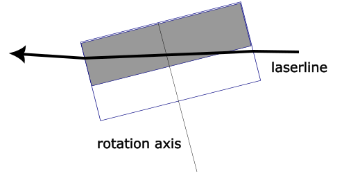
I reported to a lot of people that this is impossible to fix but might have been wrong. I did not consider the following configurations. It might be fixed if the prism is configured so that the incoming rays and outgoing rays are refracted through different parts of the prism. This allows one to tune the properties specifically for either incoming or outgoing rays.
This can be achieved by tilting the prism and not hitting at 90 degrees of the rotation angle or adding a wedge to the prism so the light is directed upwards and exits at a different height.
In the figure below, the side view of a prism can be seen. The rotation axis is not at 90 degrees with the incoming laser. The axis is denoted with rotation axis. The laser propagates from right to left and is denoted with laserline. The prism has a high and low area, illustrated as grey and white in the figure. In reality these areas can have the same refractive index and material. They can be indistinguishable. While refracting the laserlight crosses these areas. As a result the light enters and exits at a different height in the coordinate frame of the prism (not figure). As a result you can alter the gray prism in either material or shape of the surface, so it is optimal for outgoing rays given your application. This was not possible prior as the rotation axis was at a 90 degrees angle. Changes would also effect incoming rays. Now, the laser will never enter at the gray area if it rotates but always at the white. Earlier it exited at the same height..
Long story short this gives you degrees of freedom.
You could now tune the refractive index or change the shape of the prism to concave, convex, aspherical for the gray or white part and this would only effect the incoming or outgoing rays.This most likely allows you, among others to extend the laser scanline which is now around 8-11 mm.
I am 100 percent sure, I did not include this in my earlier analysis. Still, I am often wrong so next step is probably to add a simulation.
Instead of tilting the prism you could also hit it at 90 degrees to the rotational direction and fix it with a wedge on the lower side (white area of the prism). It could then be directed upwards to the gray area, or top plane.
I can imagine more weird applications. But will focus on the longer scanline....
-
PCB motor 0.6 mm pcb
06/16/2022 at 15:23 • 2 commentsCoil resistance increased to 22 Ohws. The board has a lot more power. More experiments will follow once I get back from holidays.
I added a video which also outlines why I am going for a new solution.
-
Design update 2 June 2022
05/20/2022 at 16:39 • 3 comments![]()
Changes:
decreased thickness PCB from 1.6 to 0.6 mm
mirror is placed back into the design (see my blog on optical weakness)
increased Bugeja coil size, track length coil increased to 287 mm from 144 mm
changed pinout (adapter board should no longer be needed)
diode voltage over all motor pins can be measured
resistor can be used to scale down motor driver voltageExpected Results
Track length coil increased with factor 1.993Radius where poles are placed on increased from 8.25 to 11.25 with factor 1.36. (torque is radius * force)
PCB thickness decreased to 0.6 mm from 1.6, square law implies factor 7.
If it is assumed the board can loose 1.7 Joules via convection**, current is expected to be 0.24 Amperes.
Current decreased by 0.75
Motor should be (1.993*1.36*7*0.75) = 14 times strongerResearch Focus
I have been able to show that the prism can be spun and speed looks sufficient.
Current aims are
- achieve facet overlay with 3D printed encasing
- test rotational stabilityLead time
I expect to have some results at the end of July.**
I measured the board reached a temperature of 60 degrees with 0.32 Amperes at 5 Volt.
 Hexastorm
 The core idea here is that only the prism rotates and the rest is fixed. As the prism is assumed perfect