-
PCBs..
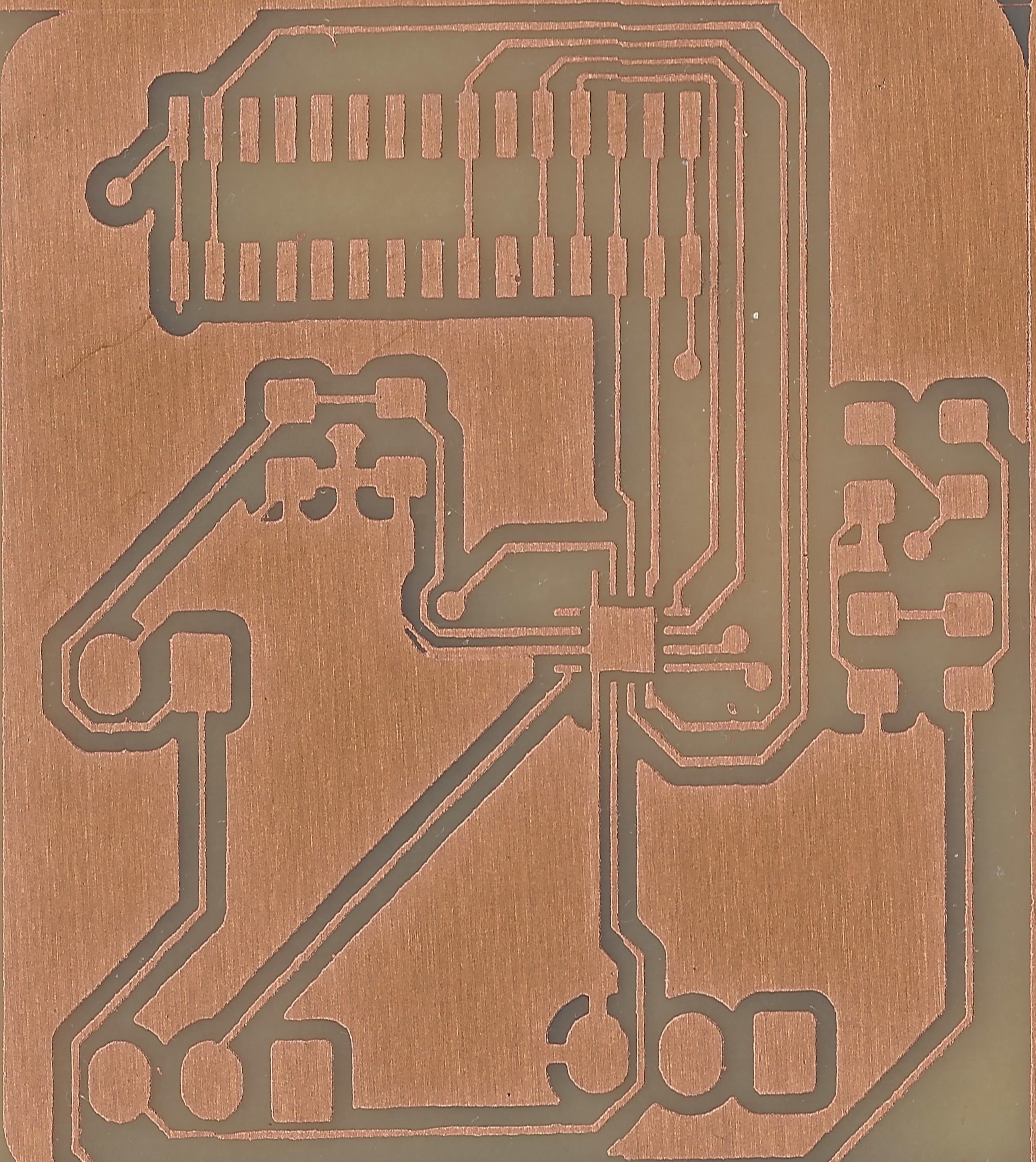
12/17/2021 at 17:17 • 0 commentsI succeeded in making some PCbs using laser direct imaging and prisms.
Track width of board below is 250 microns... the bronze colour is copper![]()
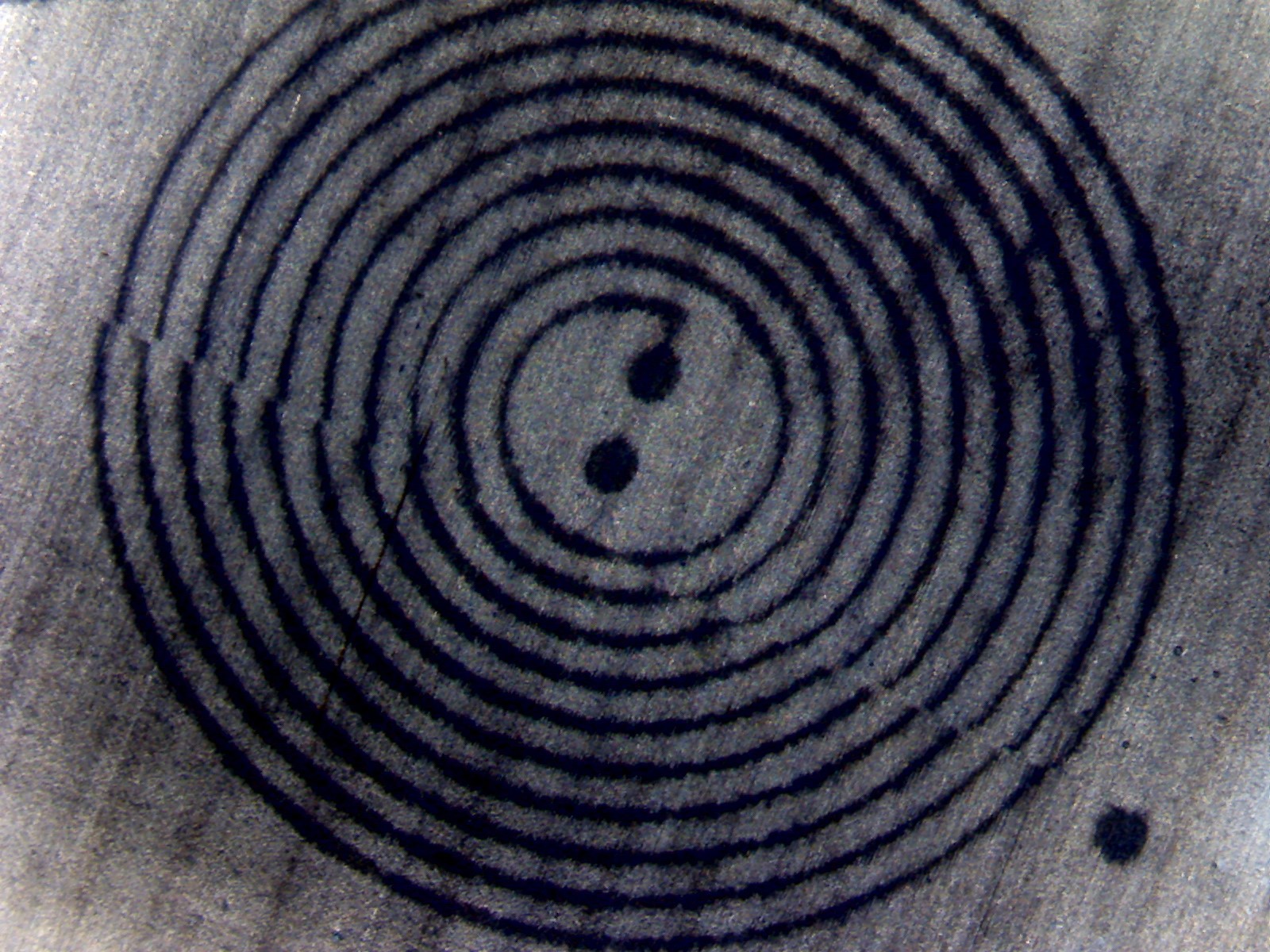
In the following picture, you see a close up of a Bugeja coil, spacing between tracks is 150 microns.
There is a mismapping of 0.16 mm between reality and board (probably needs scaling factor) You can see this discrepancy back in the board.![]()
-
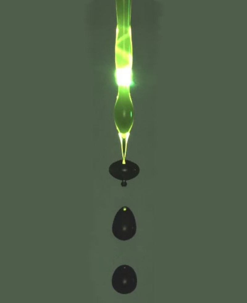
Laser Breaks Liquid into Uniform Droplets
12/14/2021 at 08:46 • 0 commentsA laser beam hitting a column of liquid controls the droplet pinch-off at the bottom of the stream.
![]()
In the past, I added some claims on that this might be possible with laser prism scanning.
Remember the post (printing with droplets) with obscure claims like I claim that the Hexastorm is used to force the break up of droplets in a continuous inkjet head using heating.
Now, there is a good write up on laser induced breakup on https://physics.aps.org/articles/v14/174 for those who are interested.
-
Theranos ideas
12/09/2021 at 17:02 • 0 commentsFake it till you make it!
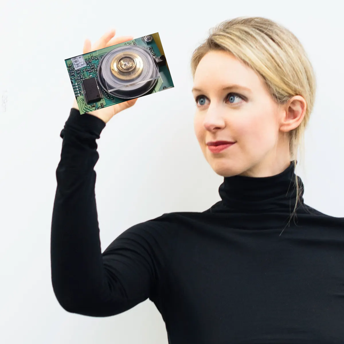
I claim the following in the field of medicine,A laser prism scanner which measures the blood nerve in the eye ball (via laser microscope), tongue or other area close to blood stream. In combination with Raman or laser acoustic, laser induced breakdown spectroscopy you can analysis the blood stream, skin cells or blood.
Using laser induced forward transfer you could emit a droplet and then transfer it into to the nerve. Virus probably doesn't need much help.
Another method I see is that you drill a tiny hole in the skin. Like 30 micron wide or smaller. I would simply burn it with laser and hope person doesn't notice that much.
You then emit a droplet using lift and pump it in the vein 😀 or you emit the droplet in the nose using lift.
Could work 🤔, I think approach should be easy for people having ordinary skill in the art of laser prism scanning. Fake it till you make it. Note that viral particles are really tiny. Also some bacteria, so droplet doesn't need to be large.
I couldn't resist;
![]()
-
Prism motor, bugeja style
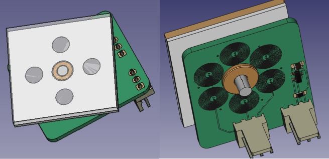
12/08/2021 at 16:04 • 0 commentsI made a custom Python script, to create Bugeja styled pcb motors. The original design is quite expensive to make. I increased track width to 150 microns and track distance to 150 microns. I have a shaft of sinter bronze. I place my prism on top and attach the rod with glue at the center. A laser cut part is attached to the prism and this is used to place the four neodium magnets.
I will probably post a video later..
Top and side view are shown below
-
Startup update
12/05/2021 at 14:41 • 0 commentsIt's always good to know what's pushing people forward.
Spiden: light + ai + biomarkers
Impressive startup in Switzerland which uses among others Raman spectroscopy to analyze blood samples
Actually, spoke to them and they are quite impressed by my prism technology and see potential in their area.Spectral Industries: Laser-induced Breakdown Spectroscopy
Dutch Startup which uses laser-induced breakdown spectroscopy (LIBS) to analyze elements.
The laser is focused to form a plasma, which atomizes and excites samples. This light is then analyzed using a spectrometer.
Atlant3D: Atomic Layer Deposition with a sort of extruder setup.They can now deposit 400 micrometer tracks, nanomemeters thick. They are working on decreasing nozzle size to 30 microns.
I spoke to them on FormNext. Their greatest competitor is laser induced forward transfer (LIFT).
Atlant3D recenlty won the Hello Tomorrow Prize.
Still, I think LIFT with prisms would be much faster than their extrusion setup can ever be. -
PCB motors
11/26/2021 at 15:06 • 3 commentsI converted Carl Bugeja's boards to Kicad. I used his version 3 motor as starting design. I hope to have results in 3 weeks.
Five motor boards cost around 100 USD, so it could be interesting to try to print these boards with my prism technology.
I did print some boards but still need to optimize my chemical process.
I plan to place the prism on the other side of the motor board, shown below. The motor is driven using the star configuration.
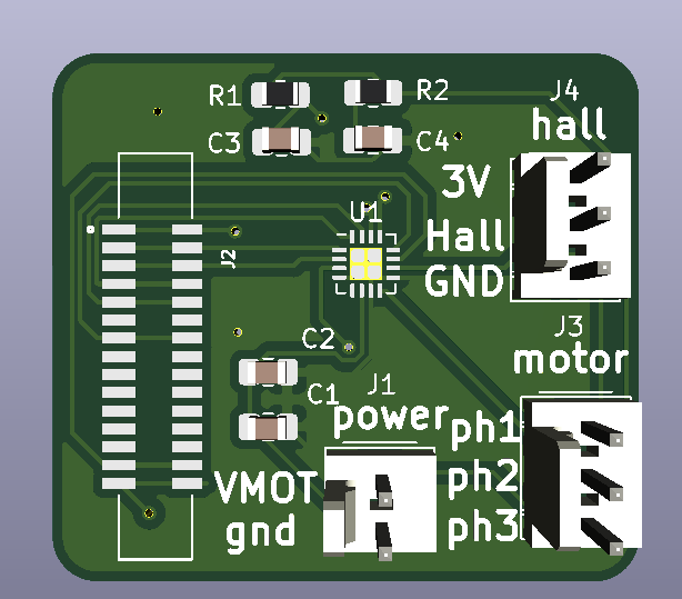
The J1 connector, connects the three phases of this motor. The J2 connector is linked to a hall sensor which measures the magnetic field and can be used to determine RPM.I plan to do the control with the FPGA, Carl bugeja used a microcontroller which I removed. The board can connect directly to my FPGA base board. The motor board (shown above) also has a base board, shown below. On it is a brushless motor driver U1). The hallsensor is connected directly to J2 which connects to my FPGA base board (not shown).
I think chances are high it will work. It would really simplify the design of my product and reduce form factor. Let's see Gravis.. if prisms and pcb motors get a long easy.
Design can be downloaded here https://github.com/hstarmans/firestarter/tree/master/prism-motor/
I will try to add a simulation of the physics, might do some trials with pyleecan. -
Closeup
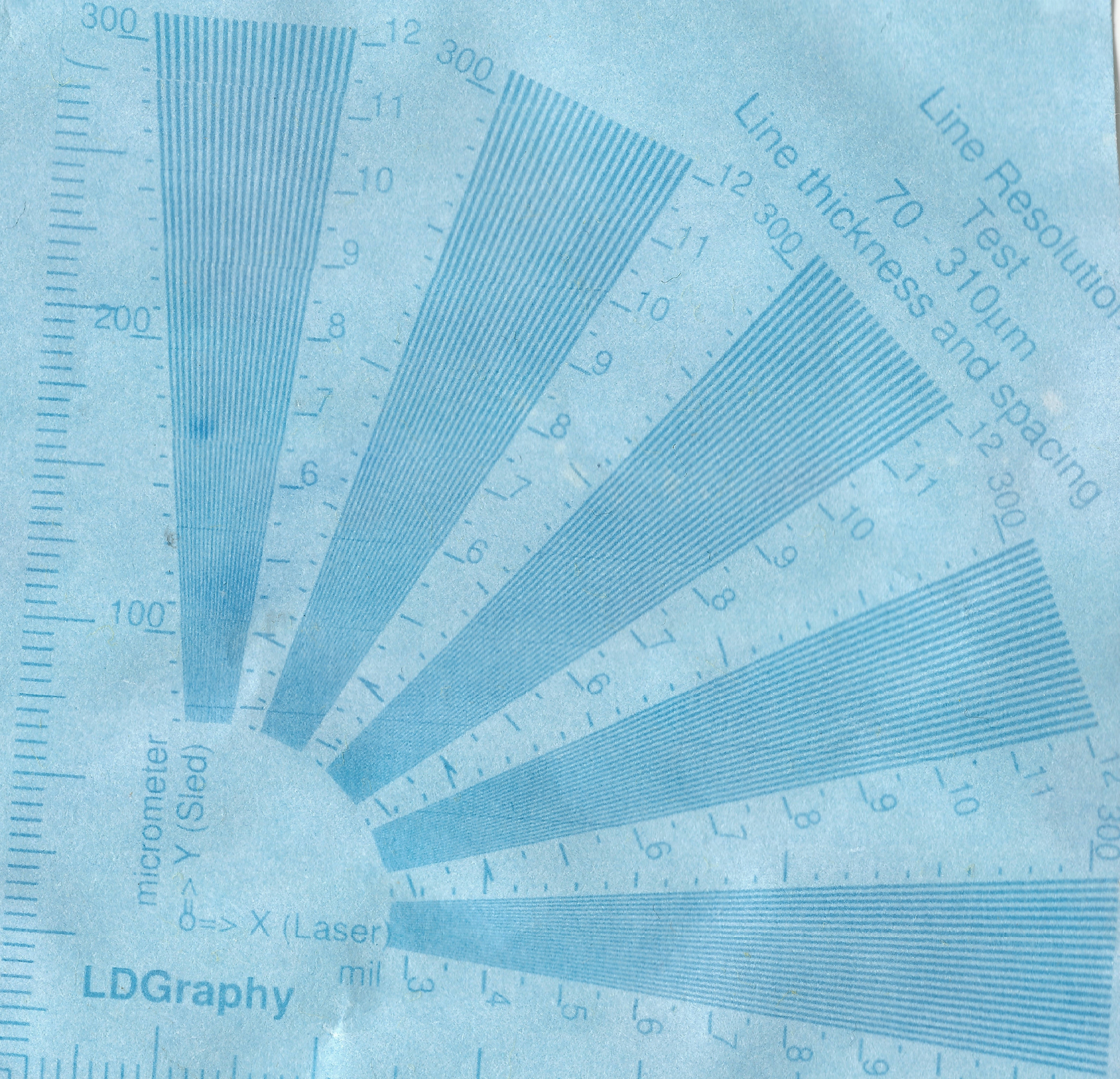
11/17/2021 at 11:07 • 1 commentGravis closeup is below; 3 mil is 75 microns and 4 mil is 100 microns. I think I can still do better if I finetune and optimize development process. Also this paper is not really intented for this type of lithography.
![]()
-
New lane alignment
11/16/2021 at 17:45 • 2 commentsNew alignment between lanes is shown below;
I have assumed backlash is zero
The width of a scanline is 5.54 mm, still I use 5.4 mm in reality, to achieve stitching.Results look pretty good. Should be more than sufficient for PCBs.
![]()
-
New laserhead exposure
11/12/2021 at 17:19 • 0 commentsResults look good even without cylinder lenses. Simply by improving the head and the prism a lot of issues got fixed.
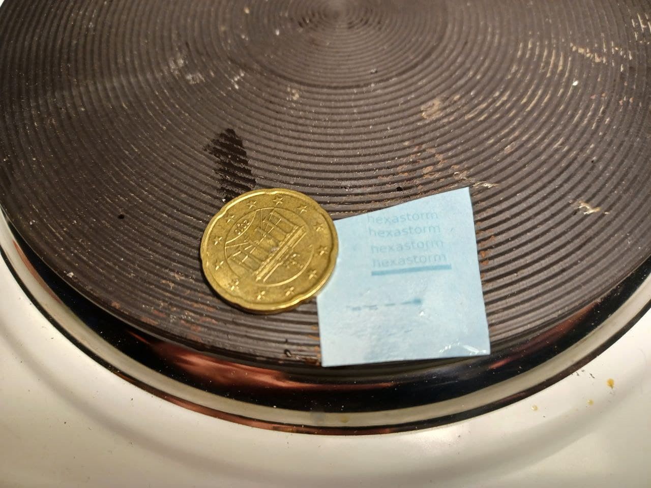
Exposure result is shown below. You can see the text hexastorm printed which looks quite sharp.
![]()
-
PCB motor
11/04/2021 at 15:38 • 0 commentsGravis asked my opinion on using a PCB motor with a prism.
In short, it seems possible to spin a prism with this motor but the prism most likely needs to be smaller.
This motor has a diameter of 15 mm, my prism a diameter of 30 mm. Of course, prism dimension can be changed.
The prism can be placed in a low drag gas like helium. So far Carl seems to focus on torque and speed, an important quality for me is actually planarity. How planar is the rotation? At 5 minute 43, he shows the side ways wobble of his amazing device. This kind of wobble is undesirable and would require a cylinder pair to filter it out. This increases price which kills the low cost advantage of the motor.
Small prisms are desirable for high accuracy applications.I would try to create a digital twin, this would greatly improve understanding.
Options I see- Magpy Lib: should be easy for a quick experiment
- Pyleecan: geared to motors but does not have example of this exotic geometry
- Elmer Fem , can be linked with open foam, probably too advanced and not suited
for exploring the problemwould make the board in kicad and not altium. An interesting script i found is (given above see hackster link). It think @carlbugeja did amazing work. For the time being, I will focus on other challenges; i.e. making the tech reliable.
 Hexastorm
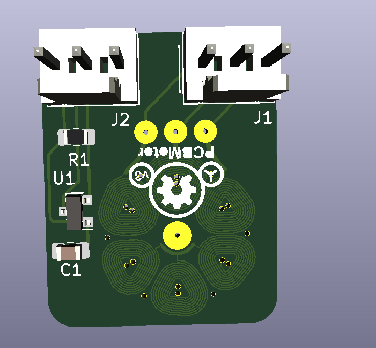 I plan to do the control with the FPGA, Carl bugeja used a microcontroller which I removed. The board can connect directly to my FPGA base board. The motor board (shown above) also has a base board, shown below. On it is a brushless motor driver U1). The hallsensor is connected directly to J2 which connects to my FPGA base board (not shown).
 I think chances are high it will work. It would really simplify the design of my product and reduce form factor. Let's see Gravis.. if prisms and pcb motors get a long easy.