Well, turns out I needed another two bank controller cards, as I just couldn’t tear down the test equatorial ring - I need to have something running. That said, of course the wiring has changed between versions.
So here’s the complete set of bank controller cards for the new camera
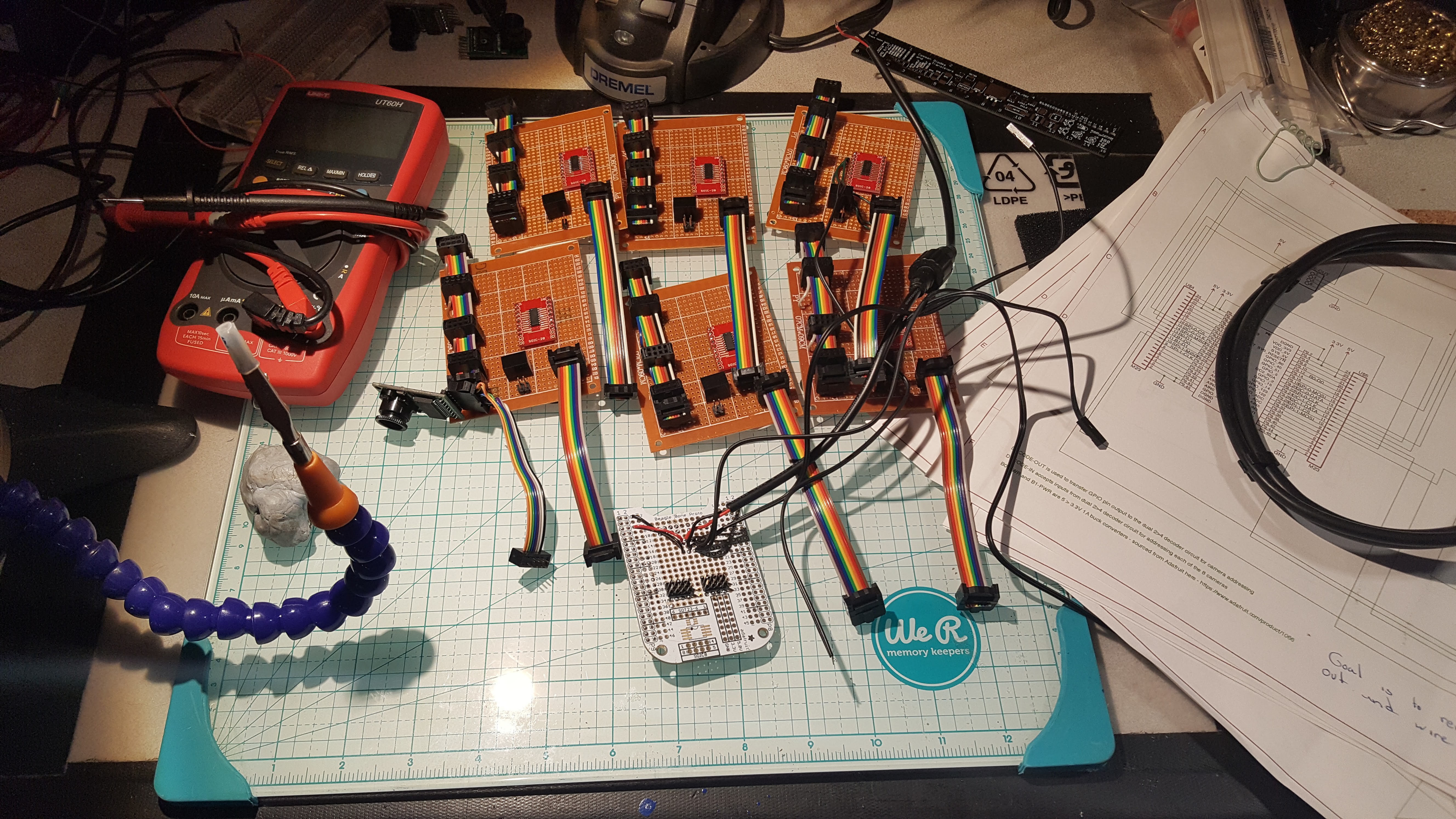
The white card at the bottom is the new BBB cape, which connects a BBB to two bank controllers and provide primary power distribution to both the BBB and the 8 cameras and associated vitamins.
Here’s a view of the front of the cape.
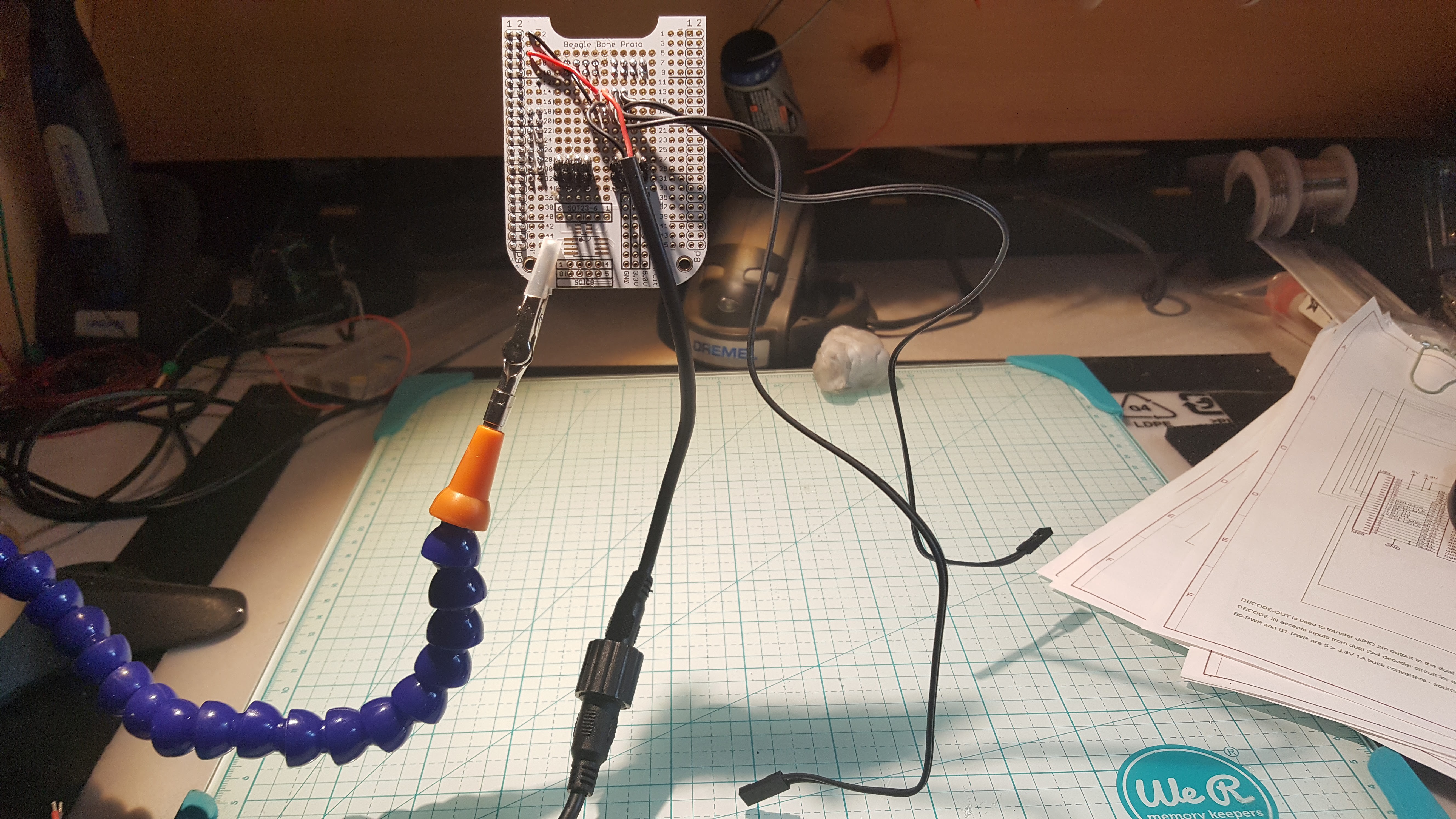
Power comes in from the connector dangling down in the middle. The connector is waterproof, allowing for external power to be external power, instead of wedging enough batteries into the camera enclosure to make it a little too bomb like for my comfort. The two black cables at the right deliver power to each of the two bank controllers, and the 2 4x2 connectors at the bottom are for the ribbon cable that connects each bank controller to the BBB.
Here’s a view of the back.
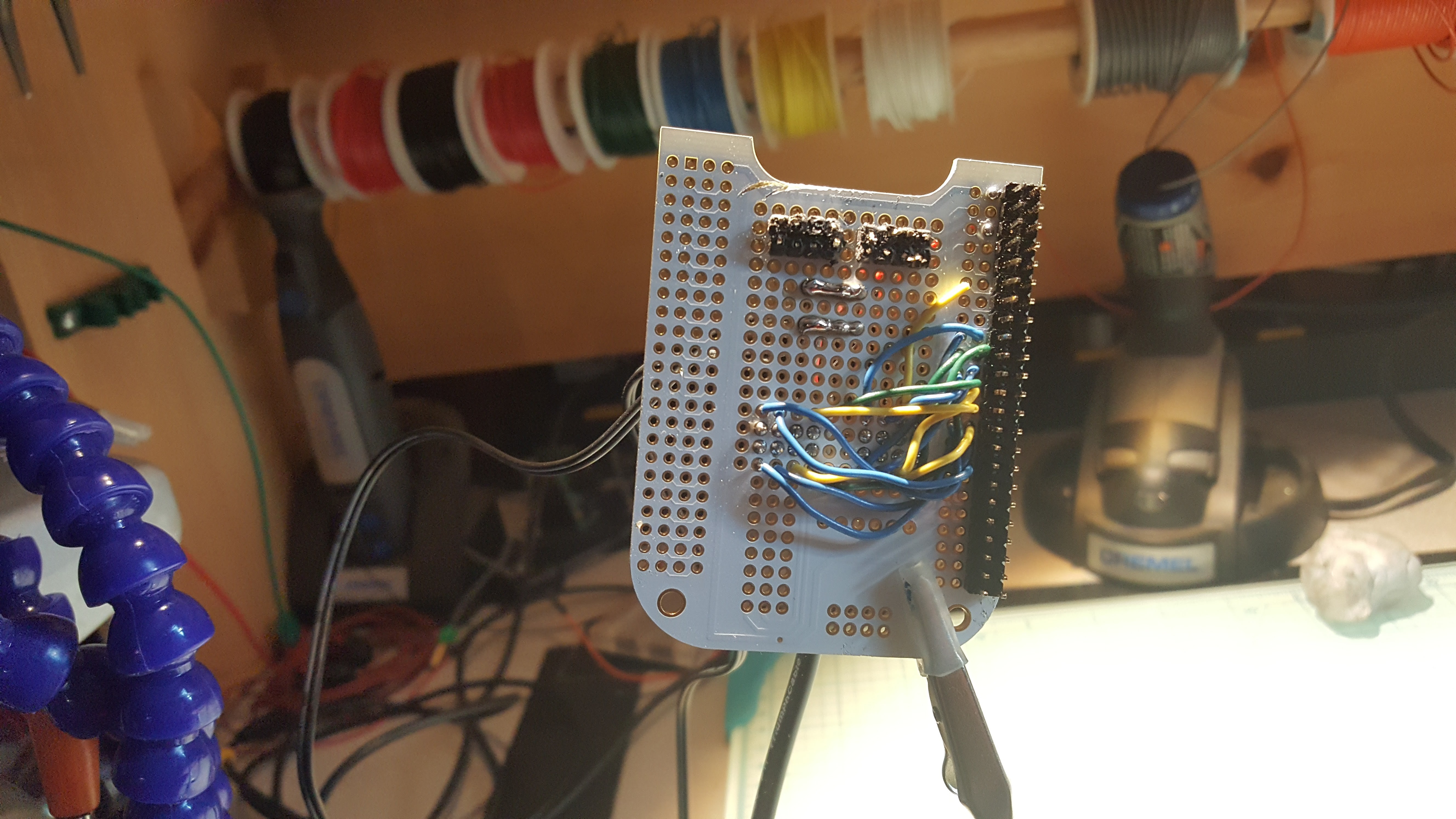
The two connectors with their pins gnawed off were a mistake. I was just too tired at that point to unsolder it, as it was both on the wrong side and wrong end of the card. The one thing I’ve noticed with all the busses I have is that you really really really have to pay attention to symmetry and you’re still likely to screw up sometimes.
So now we move on to final assembly – of course one part of that is another shopping expedition, both to replace seriously depleted parts and to get the final missing bits. Here’s what’s on hand at present.
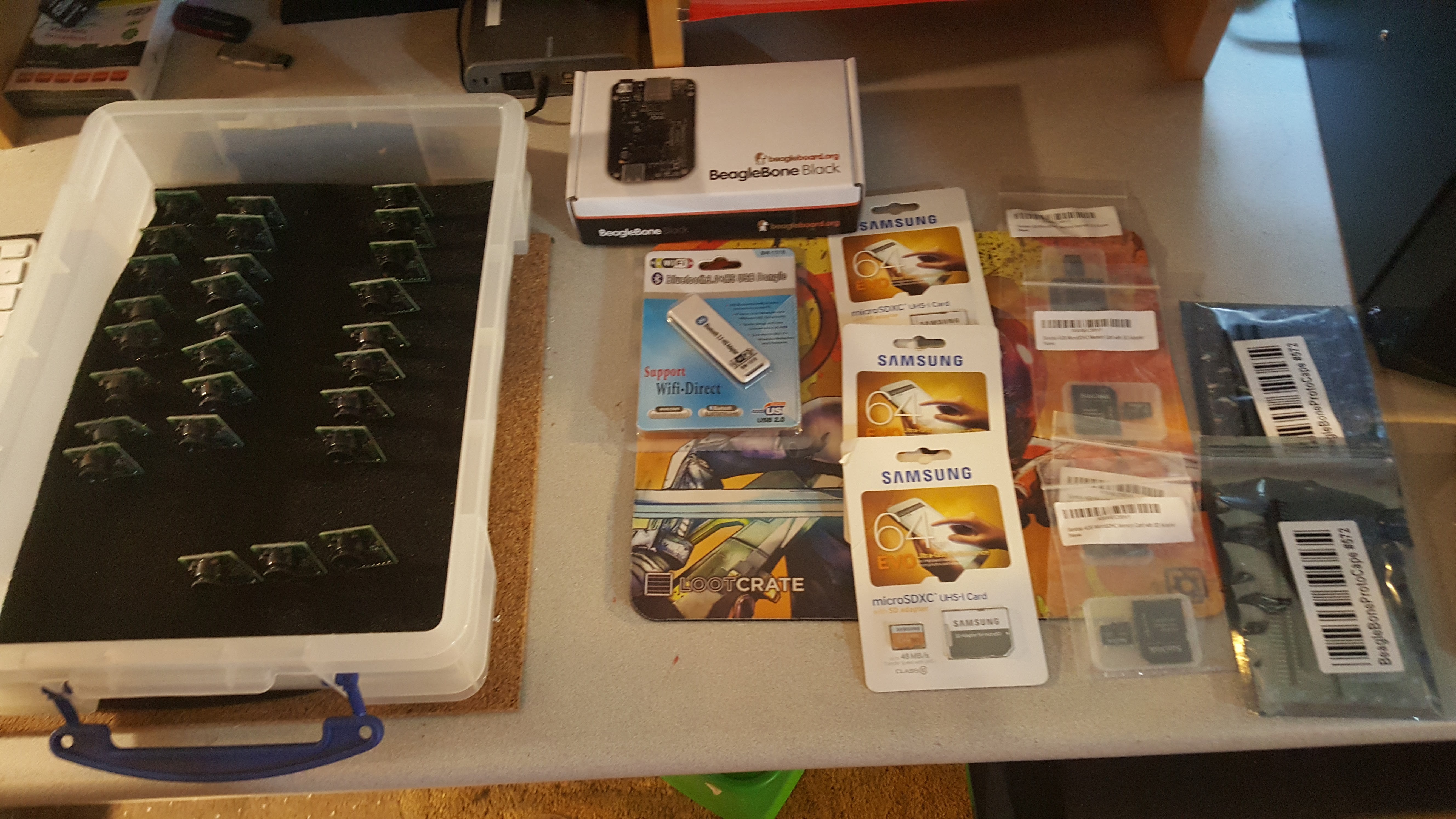
On the left are the 24 cameras for the three rings, and 3 spares. I hope that’s enough, but probably not. One BBB is at center top, 2 more need to come. The USB wifi stick attaches to the Jetson (not shown, the dev rig lives in a tangle of cables) and is used for control and diagnostics - the 3 64GB cards are used as temporary data stores for the fused hypersphere data, and the 4GB cards are used for setting the BBB eMMC. Finally, at the right are the BBB proto cape cards I still have to assemble.
Some Historical Bits, if you so care.
Given the amount of mayhem, I had to clean up the lab cause this is what it looked like.
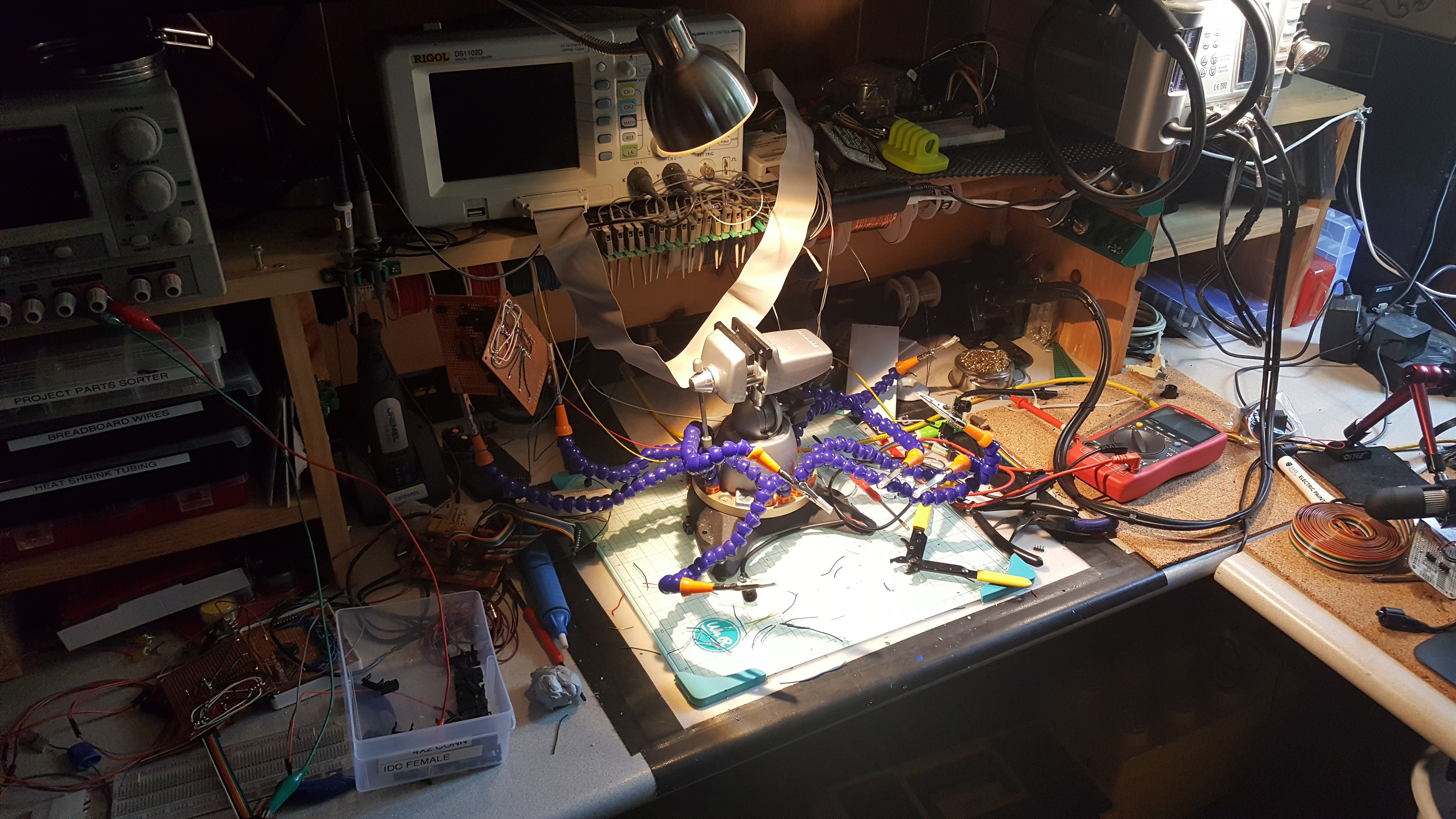
In doing that, I re-encountered a number of earlier constructions used to proof out the basic concept and circuits.
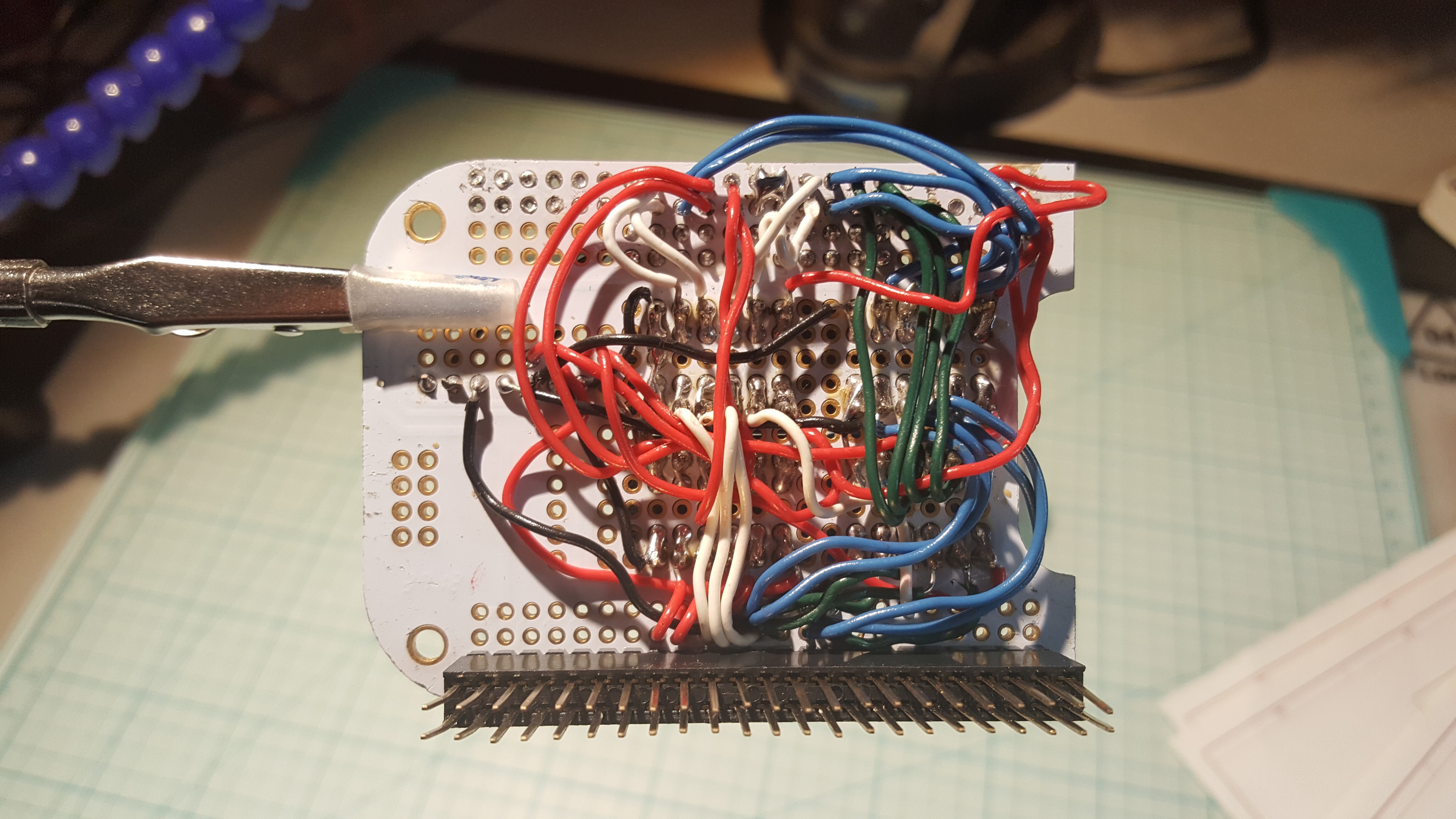
First Bank Controller
The first bank controller was constructed using level shifters from Adafruit, and the whole system ran at 5V. It was noisy as hell. Here’s the backside. Seems I’ve gone through two tips at this point with all the soldering I’ve done.
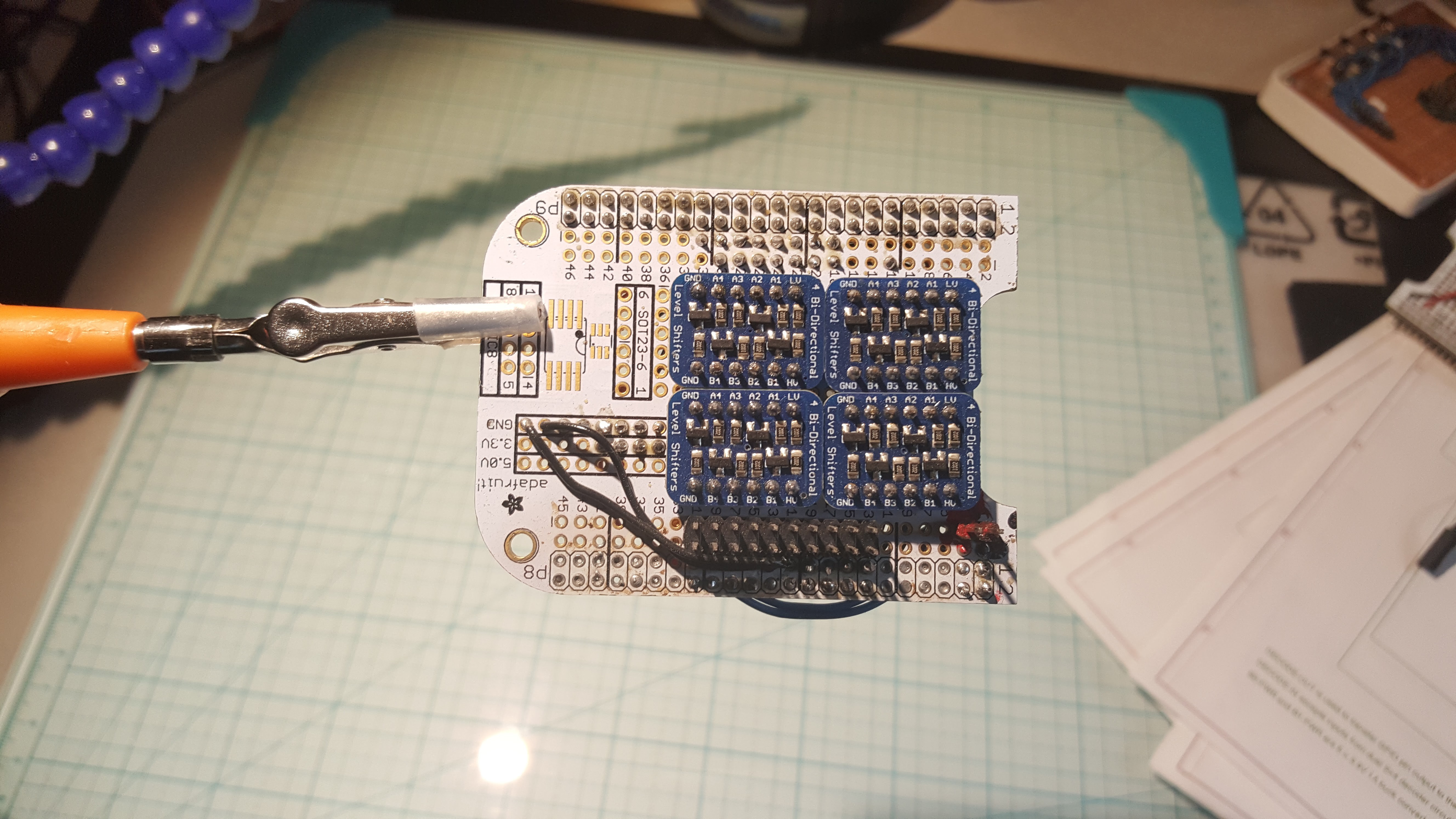
Here’s the front side – all the need for level shifters went away after I switched to 3.3V for everything except the main 5V rail.
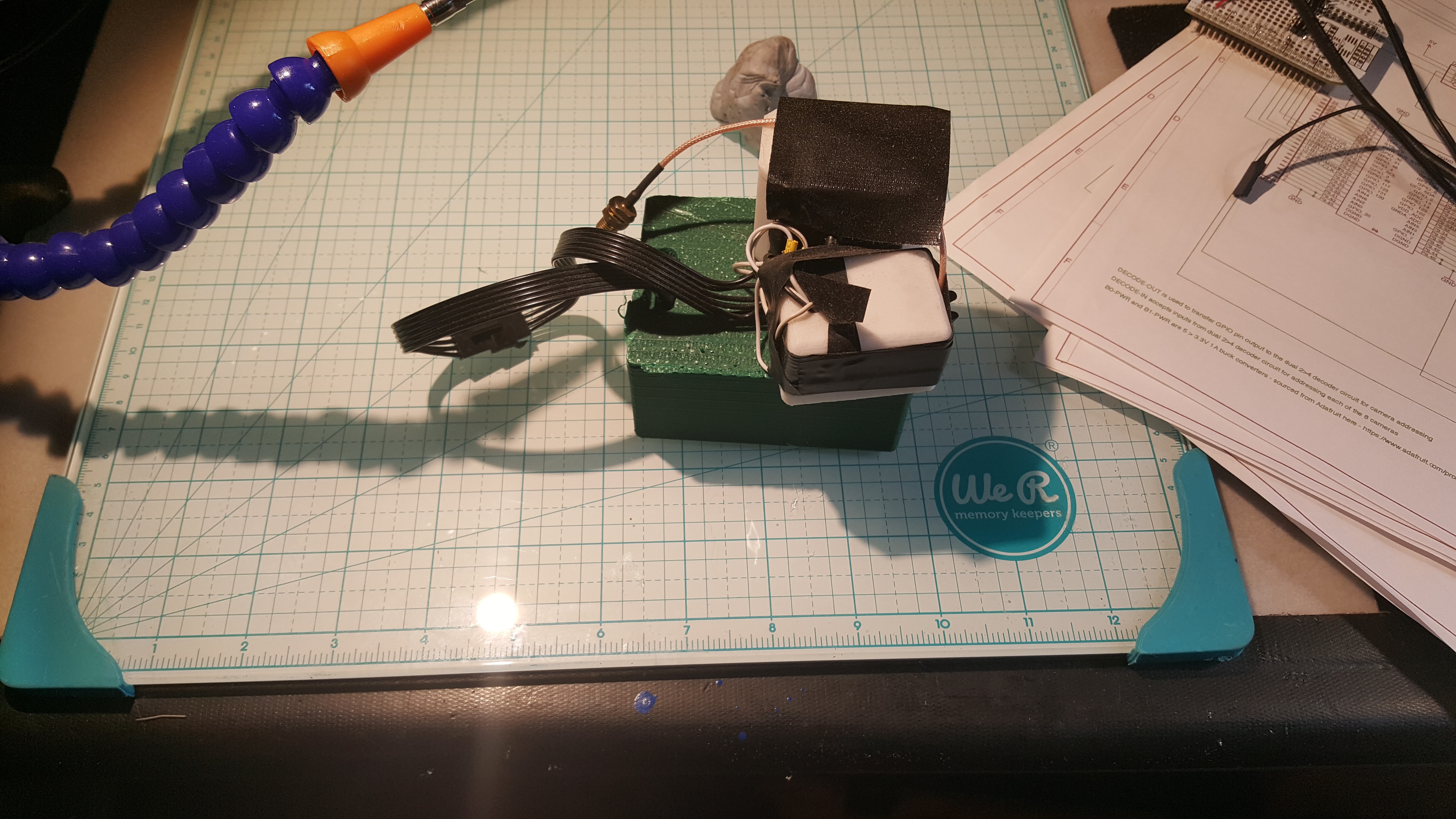
Test GPS/IMU Assembly
This went on a bunch of hikes with me – the green box at the bottom has an Arduino serving as a data logger, the smaller white box at the front contains an IMU sled, and the larger box at the back with the antenna connector holds a GPS sled.
Original 2 Camera Test Platform
The initial bank design was tested with a single hardwired camera on each bank. This tester still works as a basic test platform for grumpy imager assemblies.
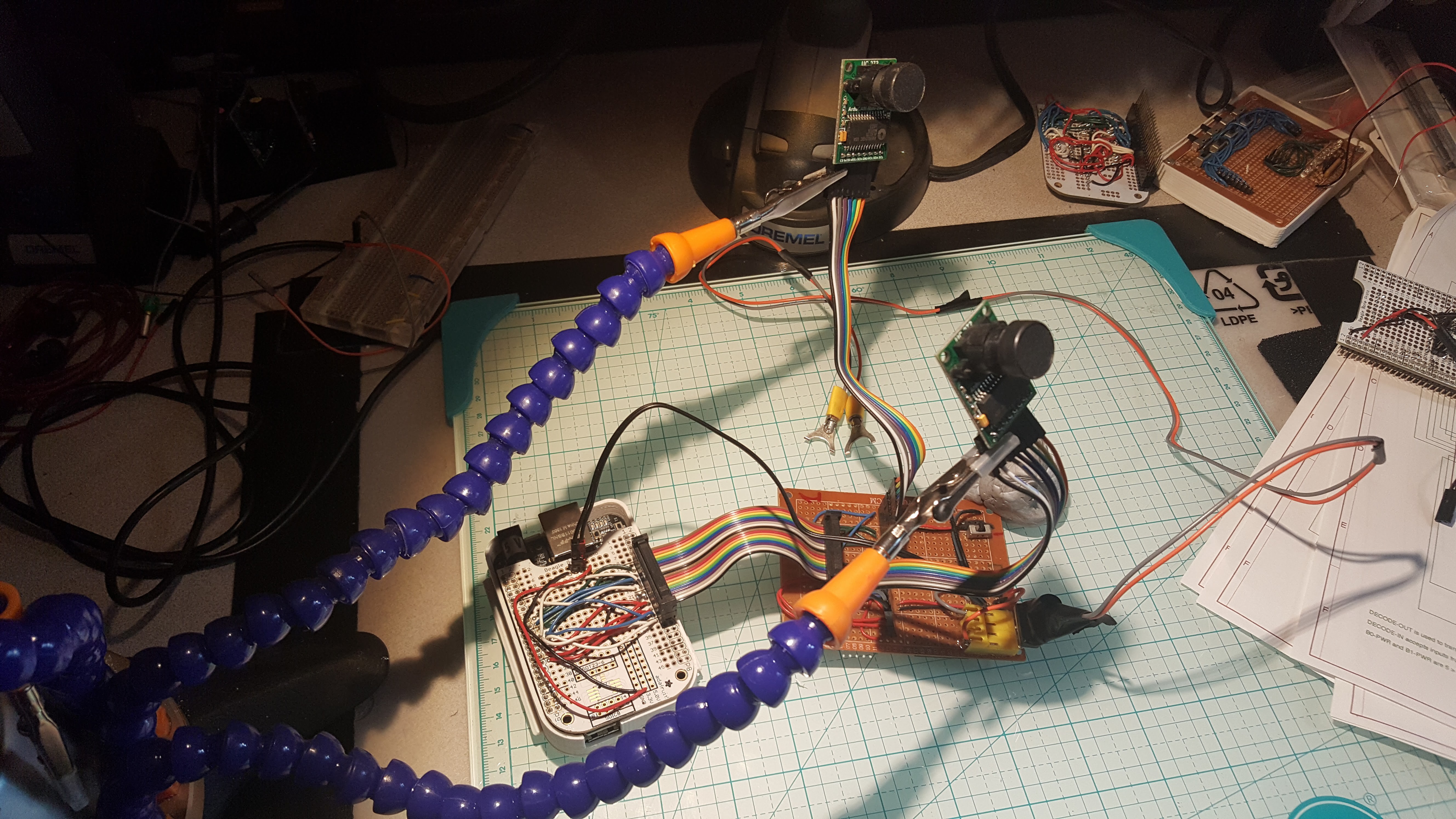
At the left is the BBB with a custom cape that pulls all the necessary signaling onto a 16-conductor ribbon cable. At the right is the camera host board, which splits out the signaling, allows the cameras to be switched in and out of the circuit, and accepts 3.3V power to drive the cameras (yeah, I rebuilt the tester after I learned 3.3V was a better way.
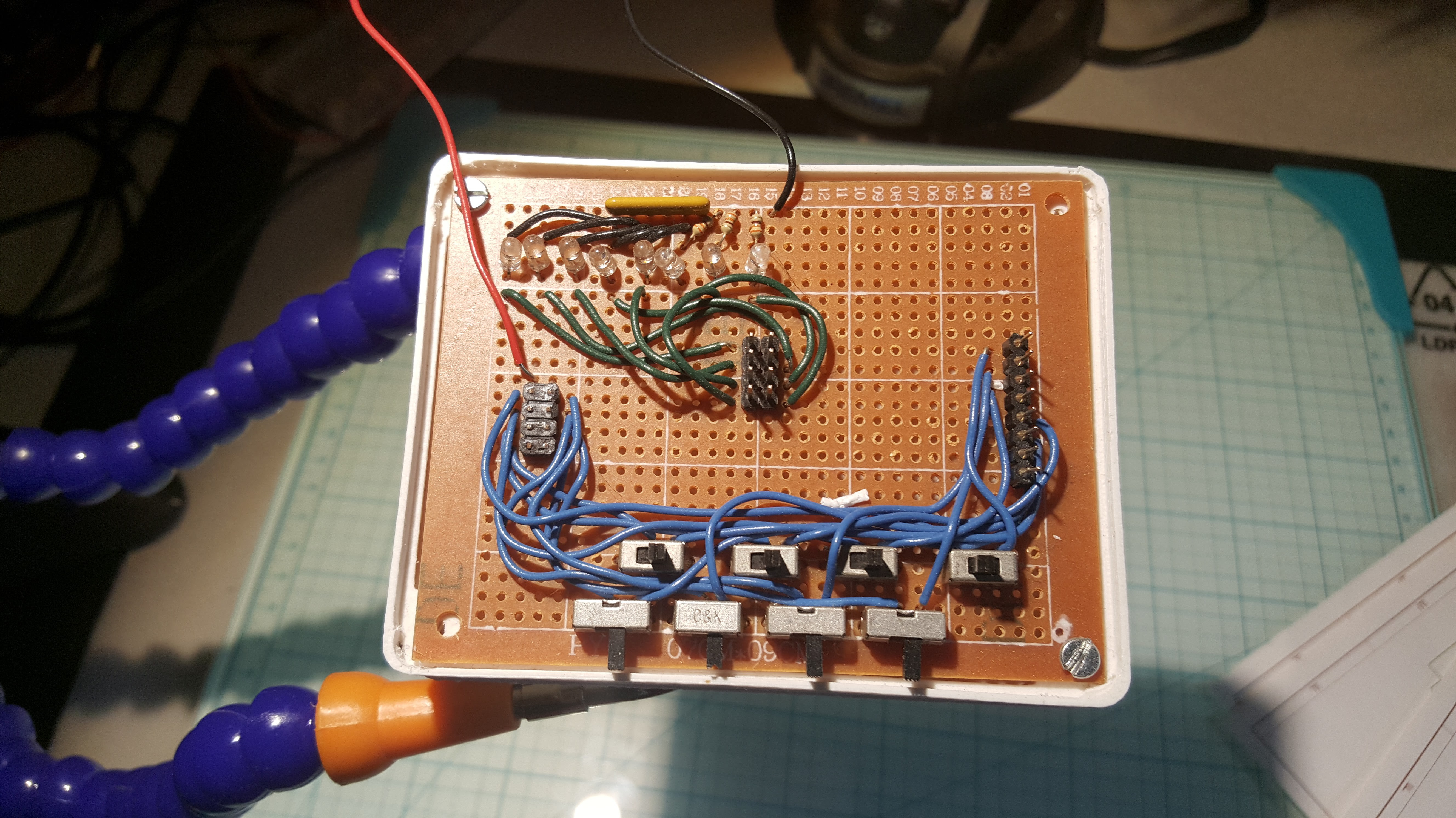
Cable Tester
This is used to confirm that the 4x2 to camera connector cable is correctly wired, by inspecting the led illumination. Still use this puppy, given I need to guarantee 24 new cables aren’t going to deliver voltage on the wrong connection.
So, the next post, with any luck, will convey status of final assembly. That's gonna be interesting. Then the stupid thing goes mobile in 1D, then in 2D, then in 3D.
 Mark Mullin
Discussions
Become a Hackaday.io Member
Create an account to leave a comment. Already have an account? Log In.