 Mark Mullin
It’s been a long hard weekend; however, the finish line is now in sight. At least for Version 1, which is now projecting a somewhat shortened lifetime…..
The single ring proof of concept being completed, the next step is to bring the entire spherical view online and begin solving error across both axes. This is primarily a mechanical exercise at this point, as the single ring tests show clearly the system can differentiate between parallax and non-parallax points (OK, it picks points that play nice as non-parallax points) however it had no means of controlling vertical integration error. With the arrival of the upper and lower 45° rings, it now has complete overlap with the equatorial ring, so overall it gets pretty good measurements as long as you don’t try and get too close to the poles.
To do this, two more Beaglebones have to be added, each controlling 2 banks of 4 cameras each, for a total of 16 new cameras. No new software is needed (yet), as these run exactly the same system as the primary ring, they’re just connected to different cameras.
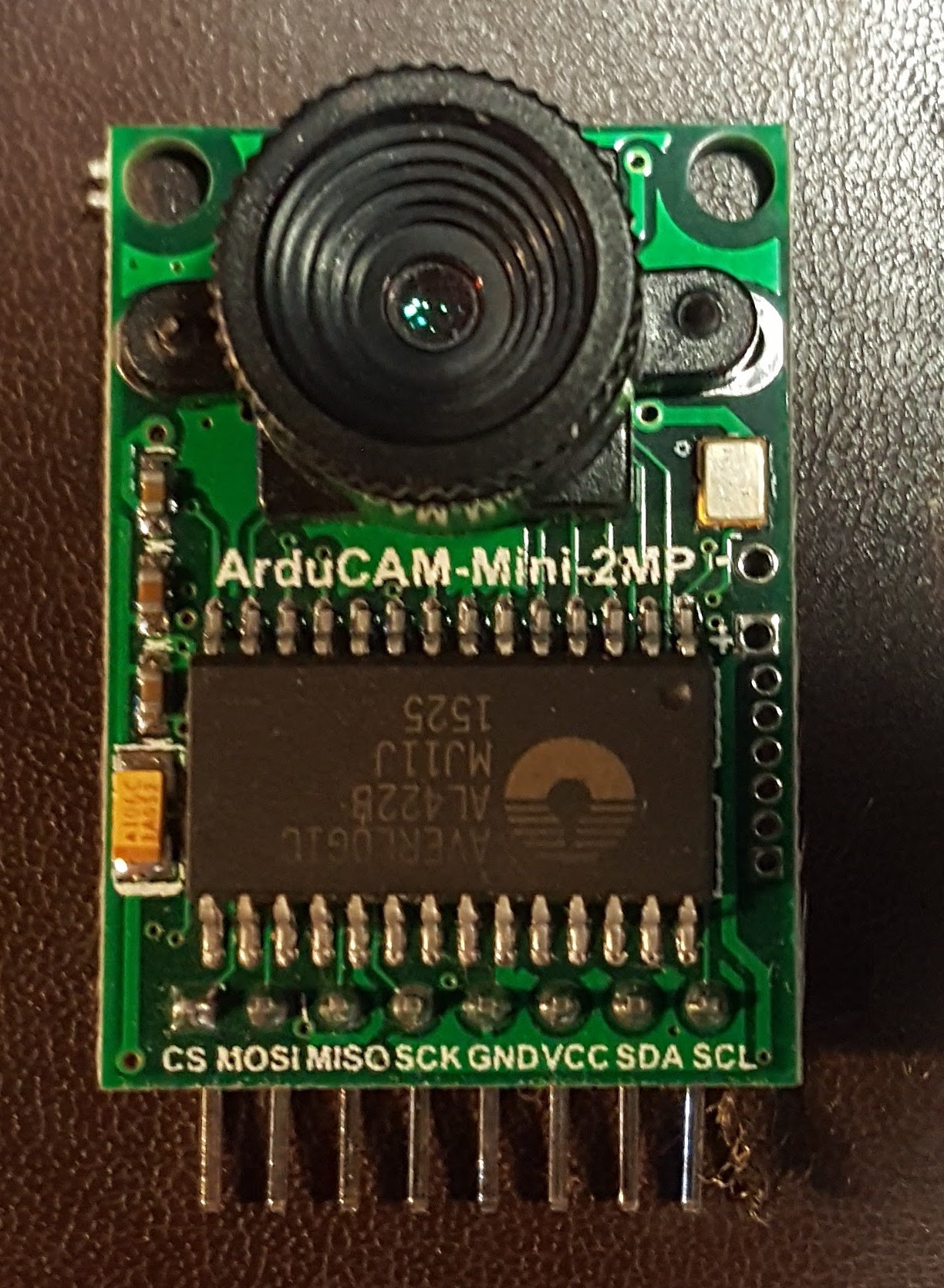
Let’s start at the beginning. Here’s a picture of an ArduCam using a OV2640 sensor, which I source from www.arducam.com - these aren’t the final cameras; they help keep the initial budget under control – the final cameras will also come from Arducam, but they’re bigger, meaner, and unfortunately, more expensive.
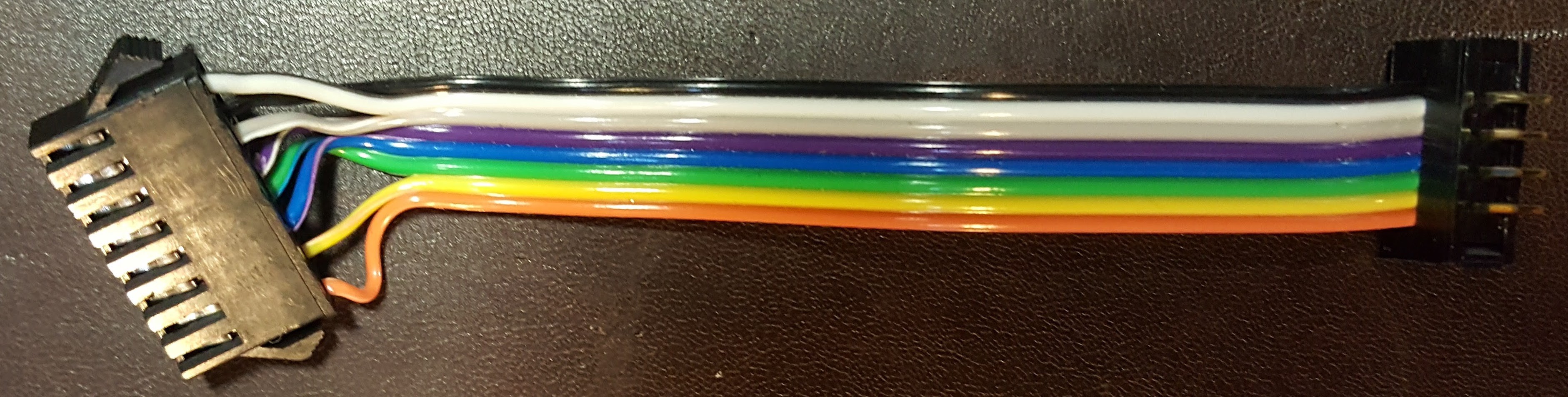
Here’s a picture of a cable that connect the Arducam to a
bank controller. If you look closely,
you’ll see that the second pair of wires from the bottom and the top pair are
swapped. Yeah, I don’t wanna talk about
it - rotational symmetry between plugs
caused a big problem – since my male header is exposed instead of shrouded
(look, those are the terms!) I had to deal with everything getting rotated on
me – worked most of it out in my head, but those two puppies were problematic
(power and chip select were the key offenders) –this design isn’t going to be
repeated in its current form and I’m using up existing stock instead of going
broke buying new stuff. Only catch is I
have to 3D print a clamp to make sure that connections stay that way.
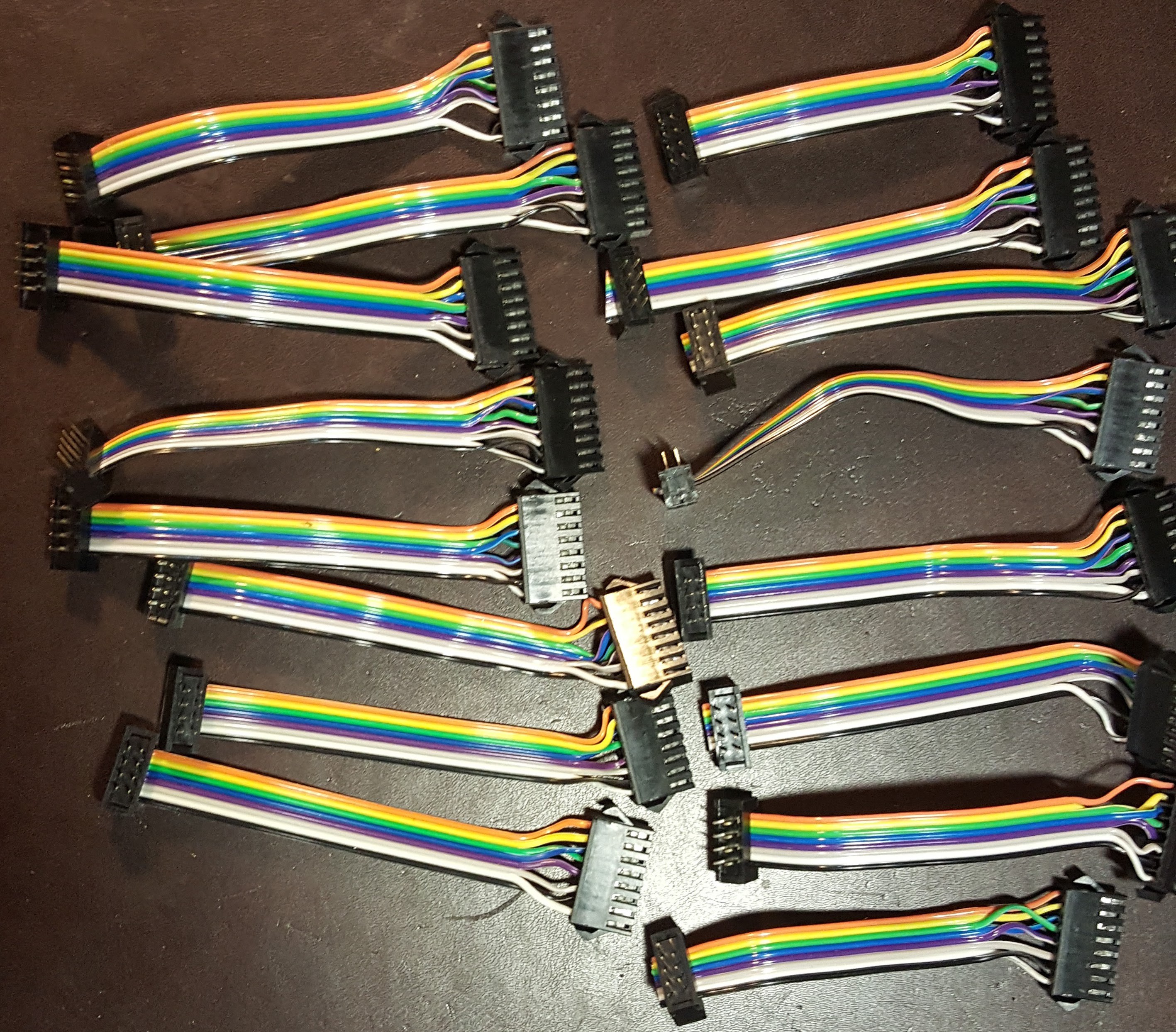
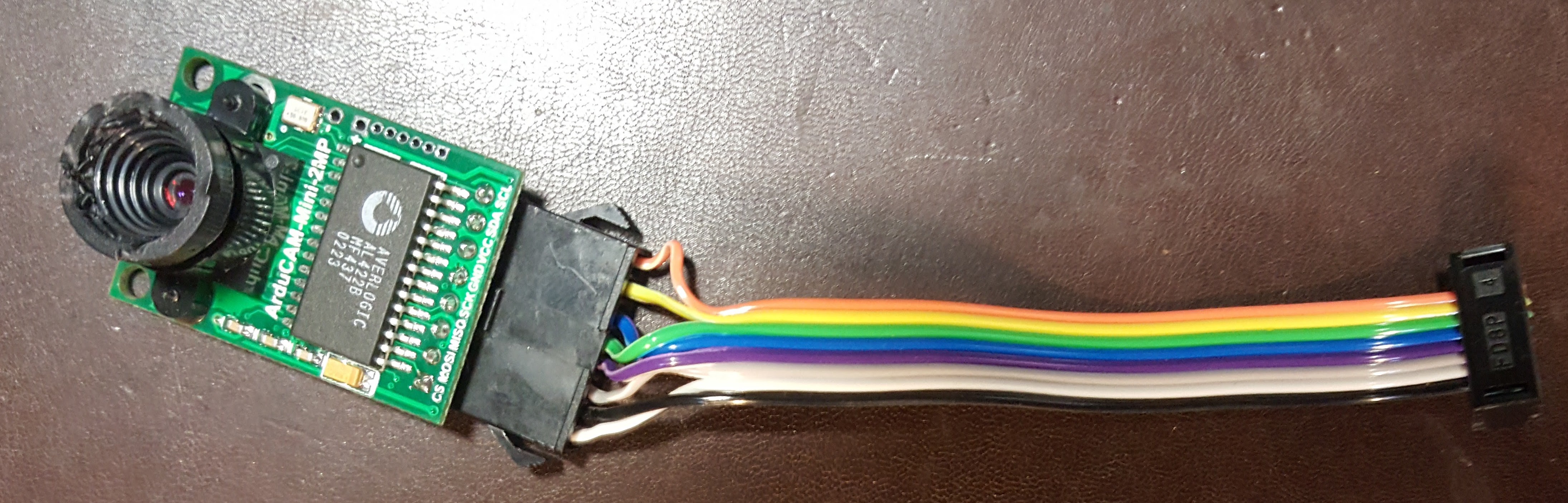 Here’s a picture of all 16 cables. JST connecters have to be
crimped by hand, twice per wire, and lets see that’s 8 wires per camera and 16
cameras - after 128 wires, some multiple
times, etc etc etc I’m truly sick of these damn things. More importantly, I can’t
put it off anymore because it’s all done.
Here’s a picture of all 16 cables. JST connecters have to be
crimped by hand, twice per wire, and lets see that’s 8 wires per camera and 16
cameras - after 128 wires, some multiple
times, etc etc etc I’m truly sick of these damn things. More importantly, I can’t
put it off anymore because it’s all done.
 Now that we’ve dispensed with the preliminaries, here’s a
picture of a bank controller. Each BBB
is connected to two bank controllers on independent SPI/I2C bus pairs – this allows
it to drive two cameras in parallel. A
bank controller provides the final interface to the four cameras in a
bank. The red SOIC sled in the middle
(Sparkfun) carries the dual 2-4 decoder described in the previous log
entry. At the top right is the connector
to the BBB cape, which carries one SPI/I2C bus pair, the negative going bank
select signal, and the two data lines that carry the camera select bits. The incoming I2C and SPI buses are directly routed
to the cable at the bottom, and the CS and data lines are routed to one side of
the dual 2-4 decoder.
Now that we’ve dispensed with the preliminaries, here’s a
picture of a bank controller. Each BBB
is connected to two bank controllers on independent SPI/I2C bus pairs – this allows
it to drive two cameras in parallel. A
bank controller provides the final interface to the four cameras in a
bank. The red SOIC sled in the middle
(Sparkfun) carries the dual 2-4 decoder described in the previous log
entry. At the top right is the connector
to the BBB cape, which carries one SPI/I2C bus pair, the negative going bank
select signal, and the two data lines that carry the camera select bits. The incoming I2C and SPI buses are directly routed
to the cable at the bottom, and the CS and data lines are routed to one side of
the dual 2-4 decoder.
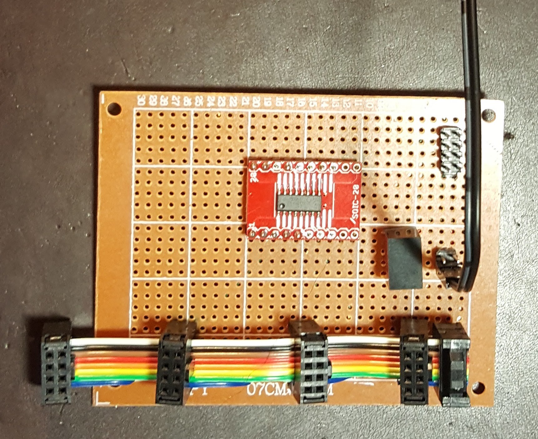 The pigtail at the center right brings power and ground into the circuit. This is done on a separate cable because the system operates at 3.3V but distributes power at 5V. The vertical rectangular box to the left of the power connector is a Traco 5.0 to 3.3V converter and is used to provide power to the decoder chip (inconsequential) and the cameras (at up to 1A each, extremely damn consequential)
This design reflects a number of conversations with Lee at Arducam about performance and bandwidth issues with respect to SPI buses, and to some degree I2C as well. While the cable assemblies were all eyeballed and adjusted to deal with soldering challenges, the goal was to use the minimal amount of wire, to ensure the wiring was as uniform as possible, and to in general, stop trying to compound an already difficult (noisy) situation. We shall see how well this works, however I do already know that a relatively clean design will net you 4Mhz bandwidth. There’s a lot of data here though………….
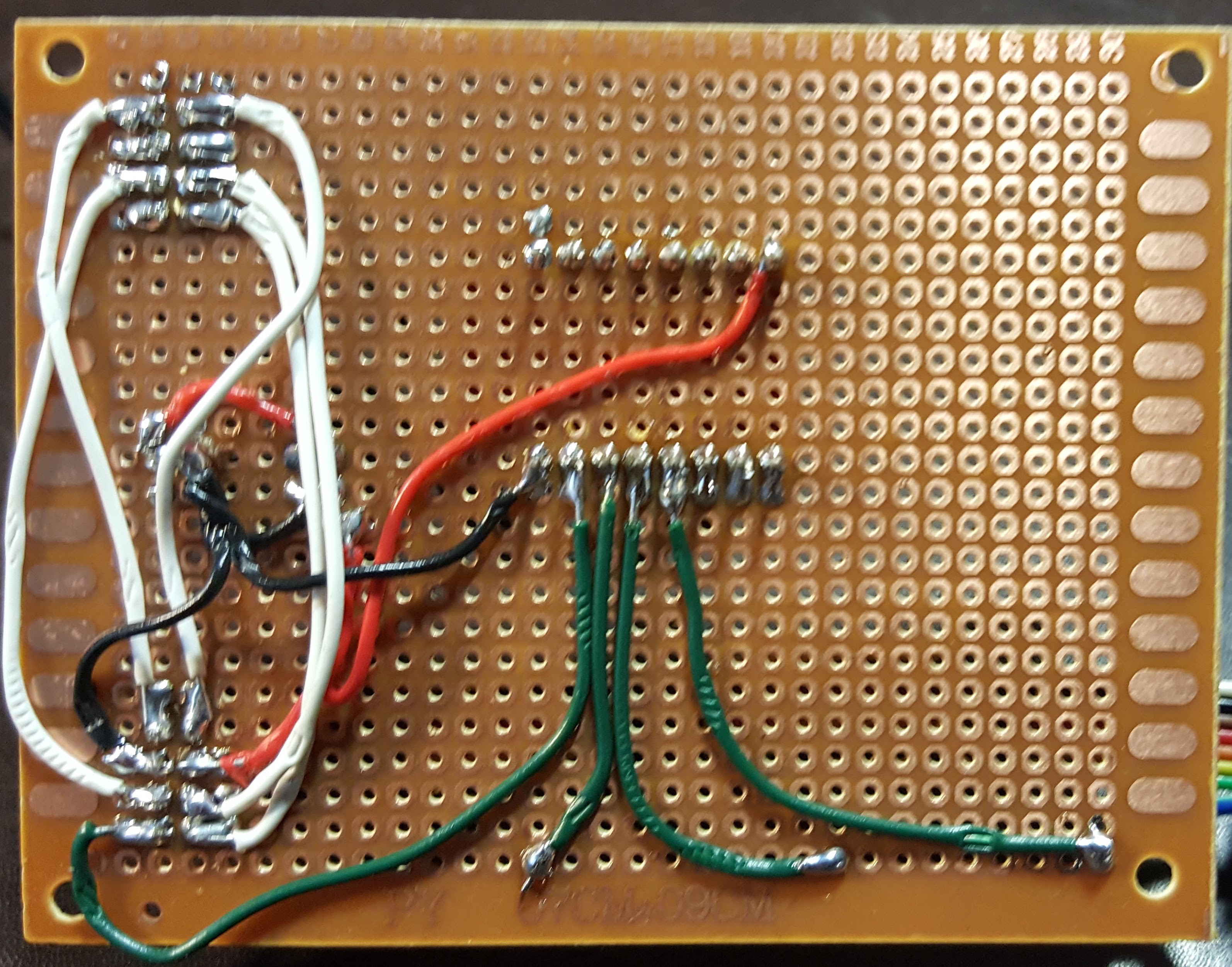
Here’s a view of the back of a bank controller. Red is 5V and 3.3V power, black is ground, green is camera select decode, and white is common SPI and I2C bussing. At the beginning of this process my smooth hemostats decided to die by fracturing a jaw and so there’s teeth marks everywhere from the toothed hemos. It isn’t that I press that hard, a busted hemo jar notwithstanding – it’s that as you do the soldering, there’s enough heat conduction the insulation gets soft and you end up goring it. Yes, the soldering could be better, but nobodies volunteering to be a lab assistant other than my son, and he doles that out carefully.
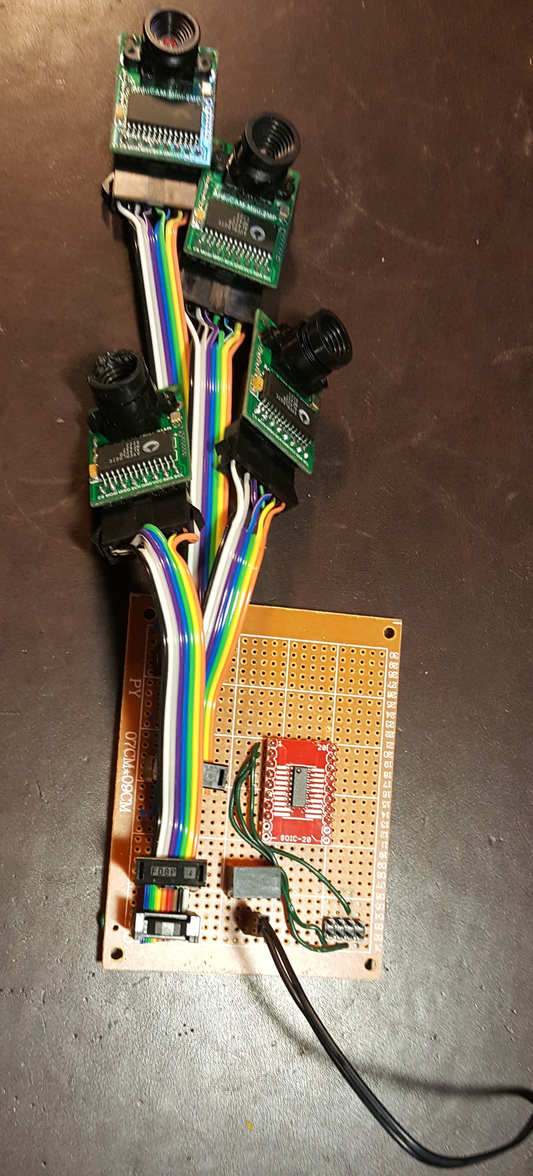
Here’s what a fully populated bank controller looks like, minus the yet to be 3D printed clamps to keep the damn cables from falling apart. Basically, when the BBB control software spins up it fragments into two pieces, each controlling an independent SPI/I2C bus pair. And then each piece races around in a circle, reading the 4 cameras on the bank controller it’s connected to in an endless game of circling the drain
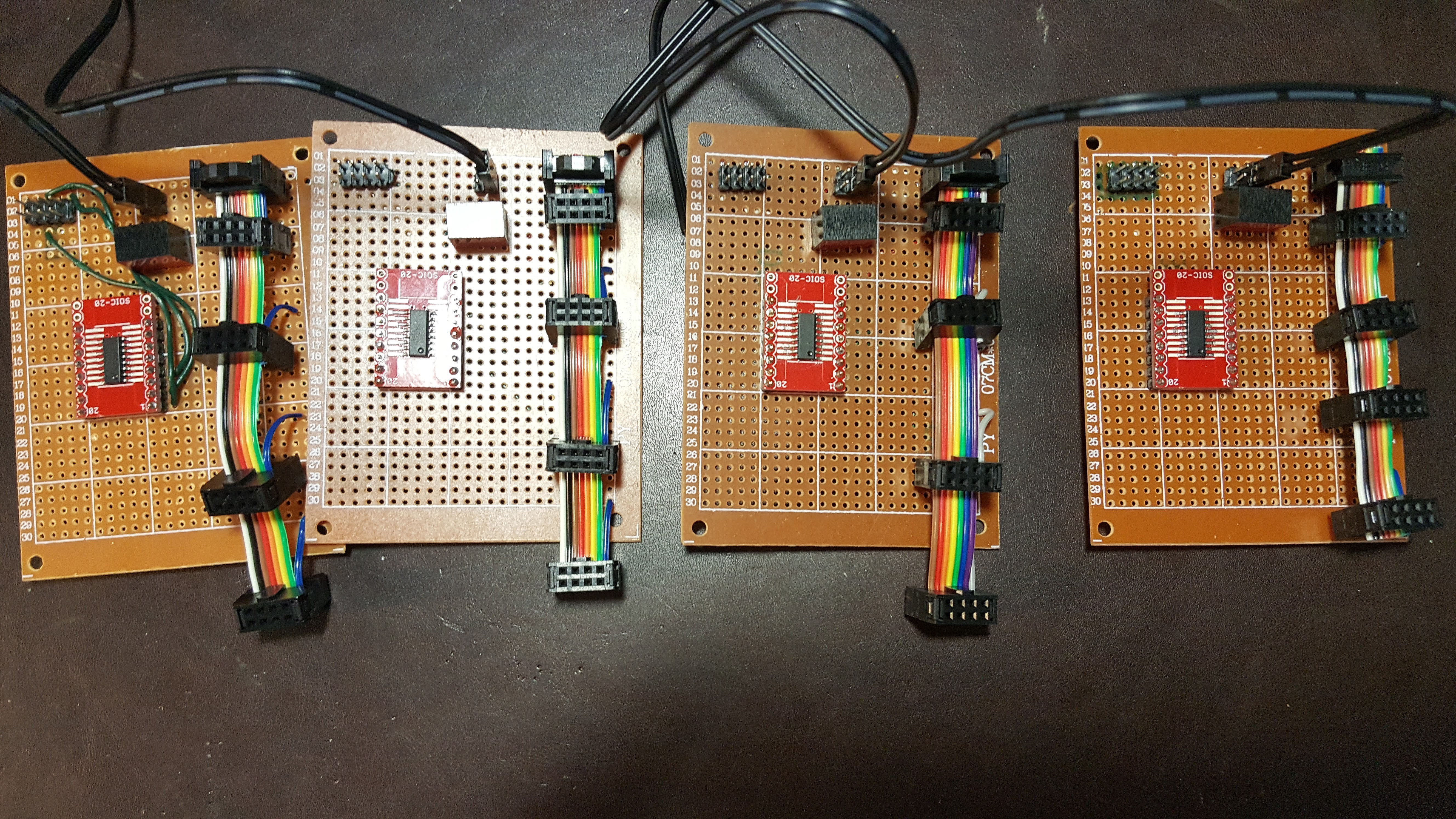
And finally, here’s all 4 bank controllers - I didn’t cable them all up with cameras because that doesn’t show any additional new information and it’s a giant pain in the ass, and the 4 cameras I did use were already busted and I really really really can’t afford to bust more cameras. It gets expensive :-)
Dear reader, if you have stuck with me thus far, allow me to thank you with two more details that others will just have to wait for. There’s been a lot of wrestling recently with CPU hardware and bandwidth issues as we amp up the cameras - the raw data rate in the system can easily exceed 500Mbps L The unavoidable conclusion is the power budget is going up because a bunch more SoCs are going to be coming to the party, and the battery weight is going way way up. So the mobility plans/constraints have been adjusted. This winter it is expected that the Quamera will move from the fixed robotic mast to a 2D mobile platform (think Roomba on steroids with eyeball from hell) and given it hasn’t either burnt down or knocked down my house, in Spring of 2018 it will move to a 3D mobile platform. Yup, first we build the house car, and then we build an autonomous flying drone. Daniel Suarez, this one’s for you!
Discussions
Become a Hackaday.io Member
Create an account to leave a comment. Already have an account? Log In.