Close
0%
0%

Debug Board Isolator

Simple, tiny USB to UART converter, also with a galvanic isolation

Similar projects worth following
Starting from
$12.80
Saimon has 1383 orders / 51reviews
Ships from Italy
I was using a cheap USB serial converter, but sometimes they didn't work correctly and i was losing time.
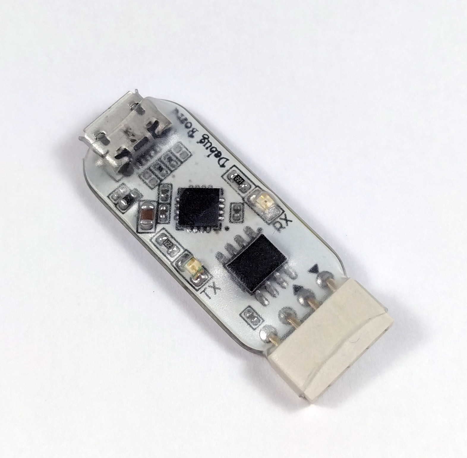
So we decided to design our own customized board, with only the essential pins. With the galvanic isolation and the possibility to work at different logic level according to the target voltage.

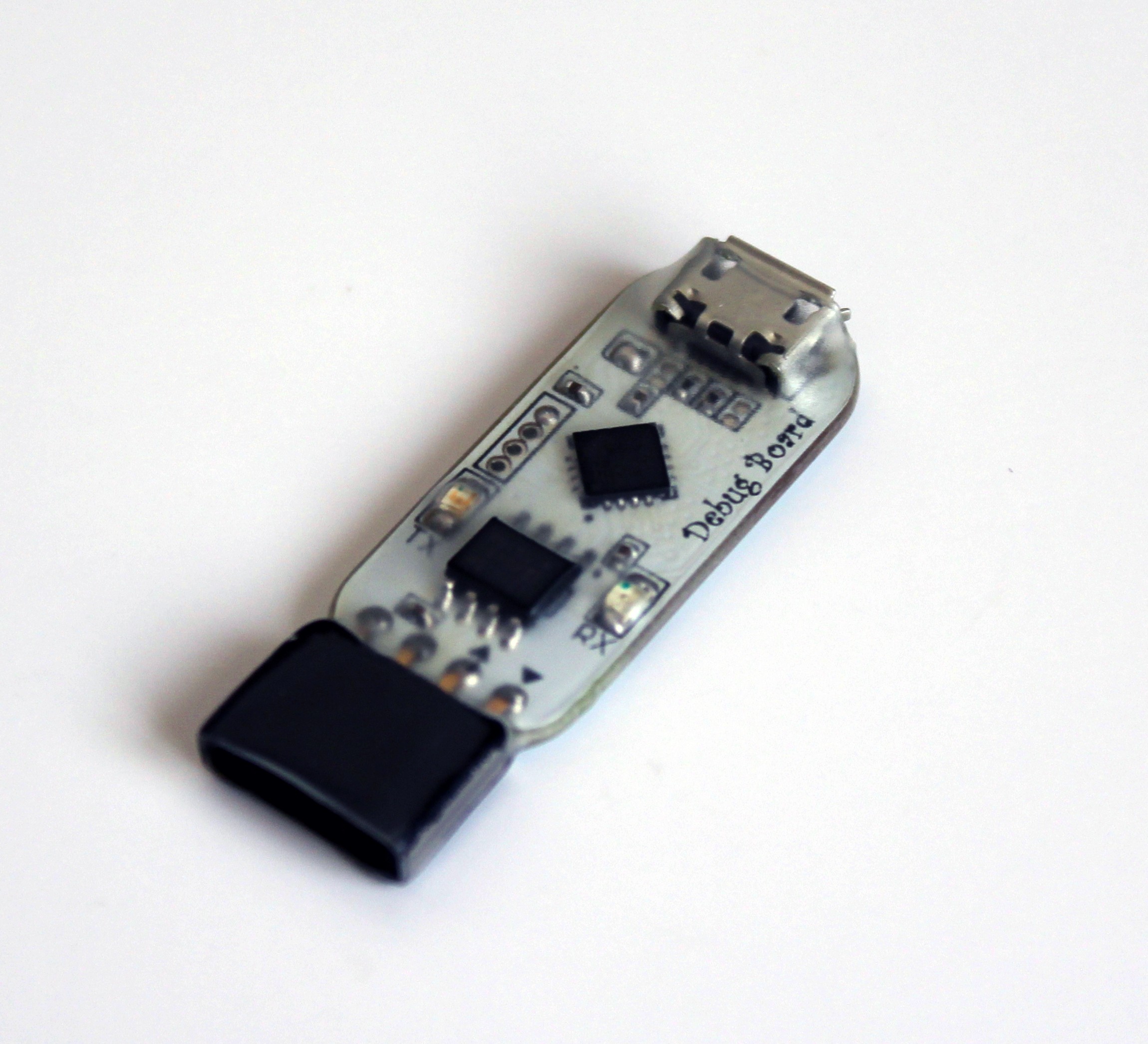
There are two types of debug boards: with and without the galvanic isolation.

The common features are:

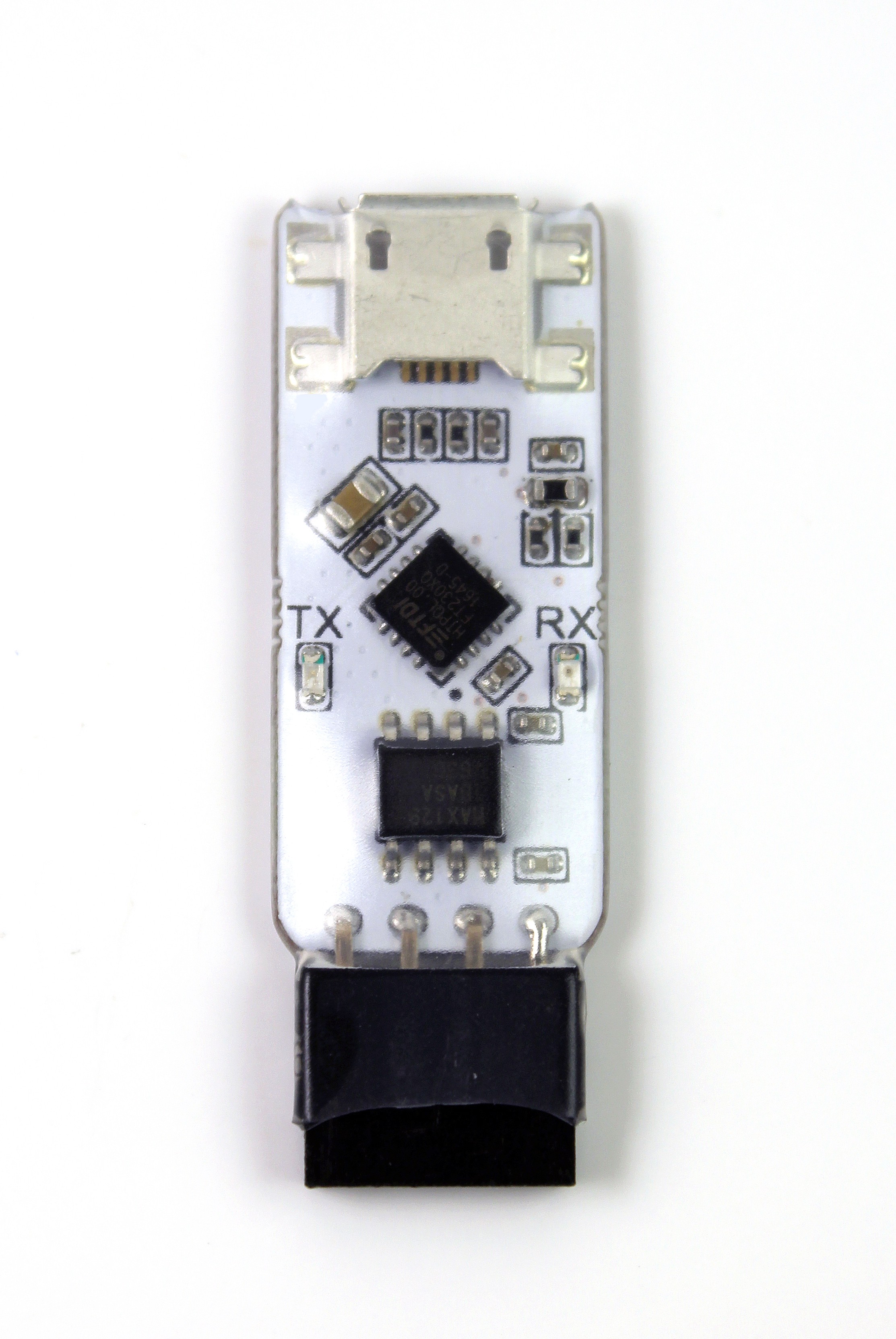
  • FTDI FT230X: Compatible with almost all the operating systems and capable of a baud rates of 300 baud to 3 Mbaud
  • TX and RX LEDs indicators
  • Micro USB connector
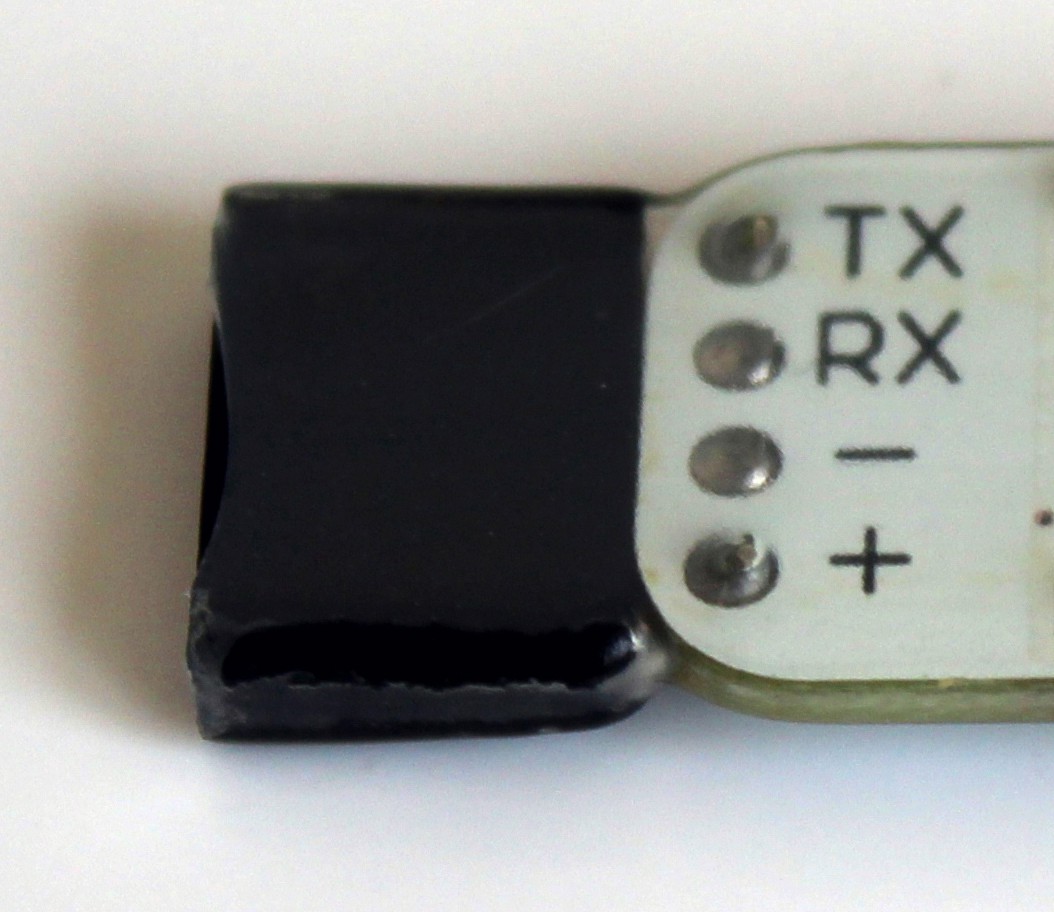
  • Standard 2.54mm 4 pins female header
  • Protected by a transparent heat shrink sleeve

Pinout:

  • TX
  • RX
  • GND
  • VCC

Debug Board with isolation:

The size of this board is just 40 x 13mm. The galvanic isolation is achieved by using the ADUM121N chip, with an isolation up to 400Vrms.

Whit this chip is possible to have the isolation between the target and the PC, plus the voltage level of TX and RX are the same of the target board. This means that it doesn't matter if your board is working at 5V or 3.3V or 1.8V, the logic levels are always correct !

This board can't give the power to the target, but you have to power it up.

Debug Board without isolation:
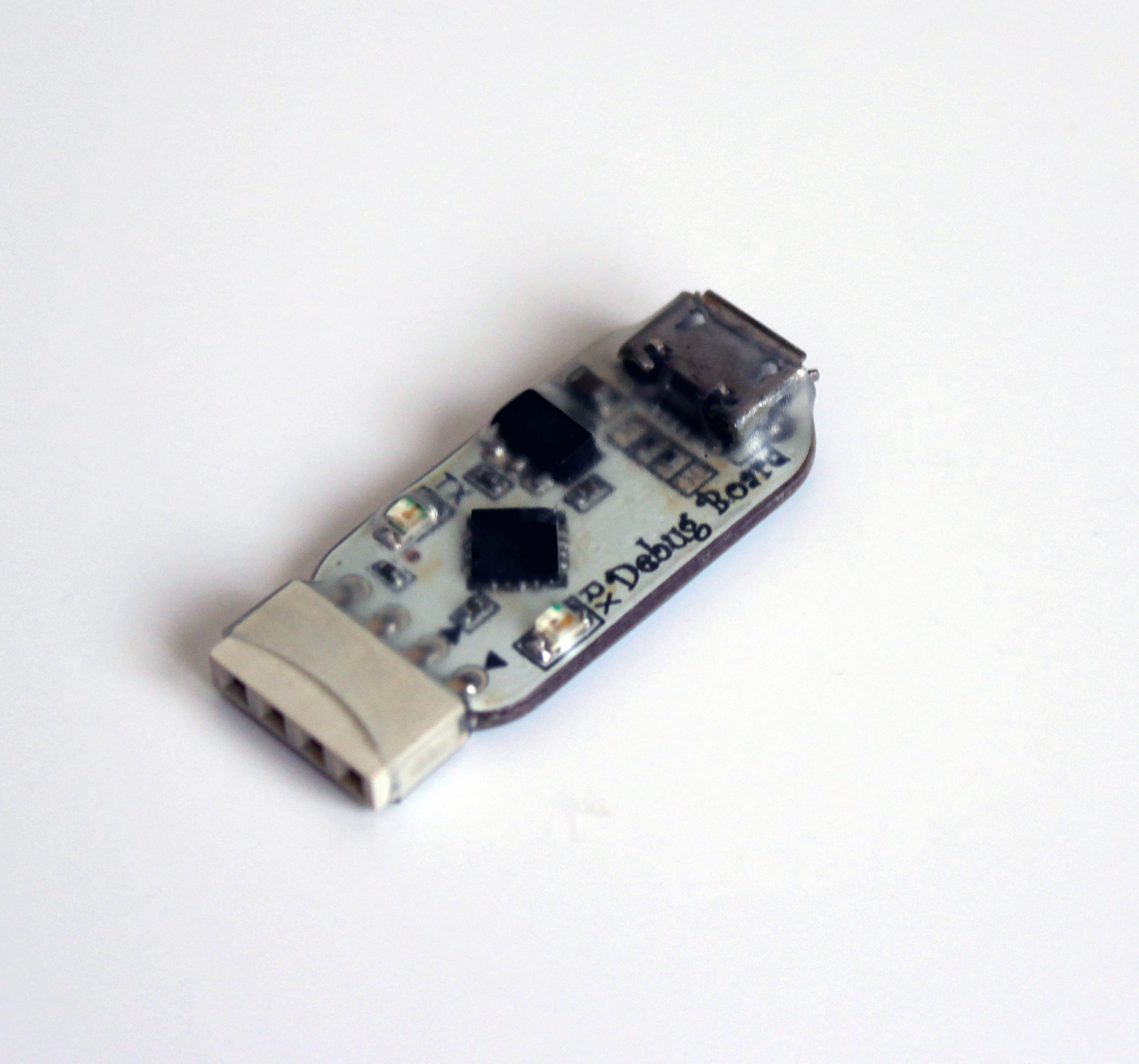
This board is much smaller respect to the previous one, with a size of 30 x 13mm.

The TX and RX voltage levels are fixed to 3.3V, but it can power up your target at 3.3V and with a maximum of 200mA.

We made a small banch of these boards and they are avaiable on Tindie

With isolation:

https://www.tindie.com/products/Saimon/debug-board-usb-to-rs232-isolated-serial-converter/

Witout isolation:

https://www.tindie.com/products/Saimon/debug-board-usb-to-rs232/

  • Testing video!

    Saimon01/07/2018 at 11:26 0 comments

    We tested the board with the main power supply 220VAC. Here is the result:

  • Eye diagram measurements

    Saimon12/15/2017 at 16:32 0 comments

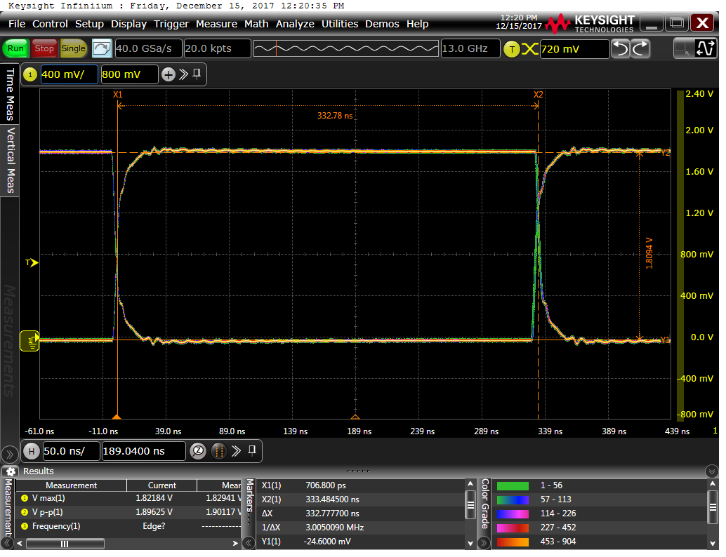
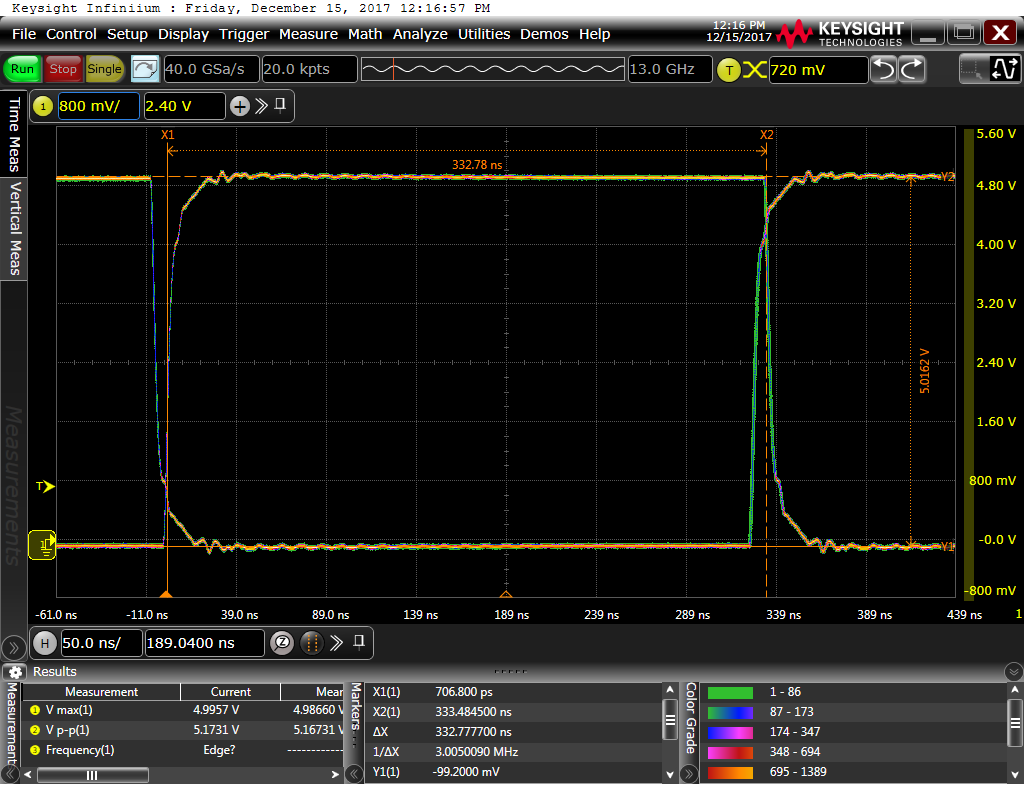
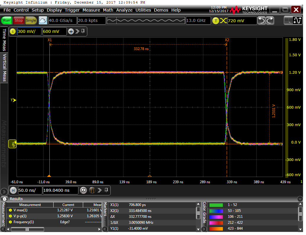
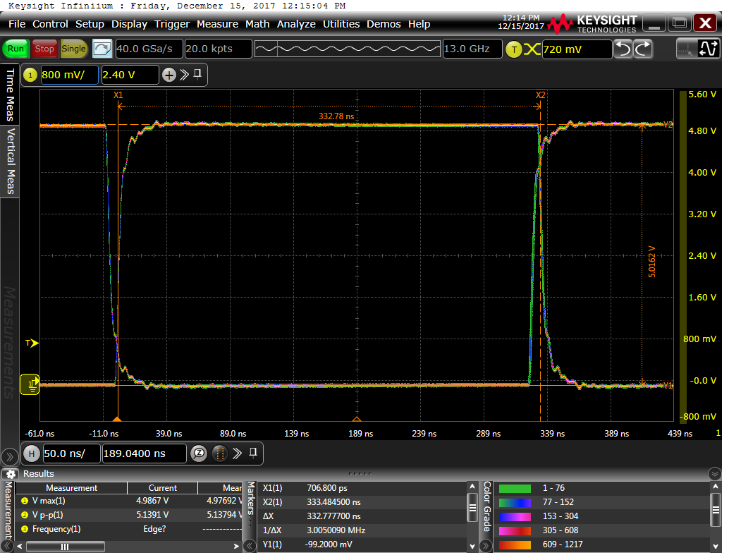
    Today at work, i got a chance to use some nice instruments at the labratory where i work. I did some measurements on the #DebugBoard Isolator and Voltage Translator TX signals.

    I used the Keysight oscilloscope DSA91304A (13Ghz a40GSa/s) and the power supply Keysight N6705.
    Yeah, those instruments are too much for this type of measurement, but they are the only ones that are available for me :D

    I did the eye diagram at 3 Mbaud and at the minimum and maximum voltage level, here are the results:

    Debug Board Isolator at 1,8V:

    Debug Board Isolator at 5V:

    Debug Board Voltage Translator at 1,2V:

    Debug Board Translator at 5V:

    The result seems pretty good!

  • Better USB connector

    Saimon12/09/2017 at 11:53 0 comments

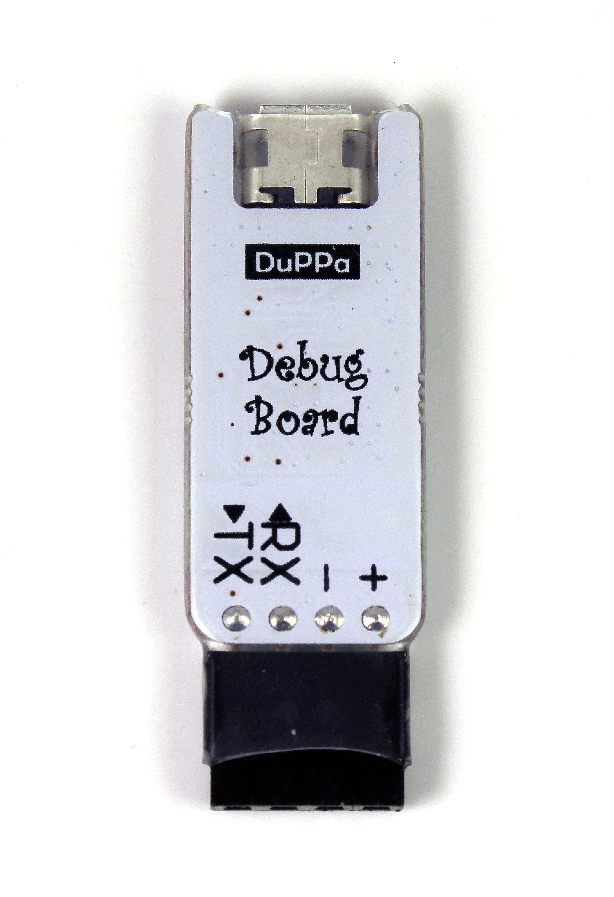
    After selling the previous version of the #DebugBoard i made a new version of the PCB with some small changes:

    • New type of USB connector
    • Clarence increased from 4mm to 4,8mm

    Here some photo of the new version.

  • New PCB version

    Saimon07/03/2017 at 20:44 0 comments

    Finally we made the new PCB release with the 4mm clarence, the rest of the board is not changed.

    For who is interested, on Tindie is possible to buy some of this board.

  • New PCB clearence

    Saimon05/29/2017 at 12:45 0 comments

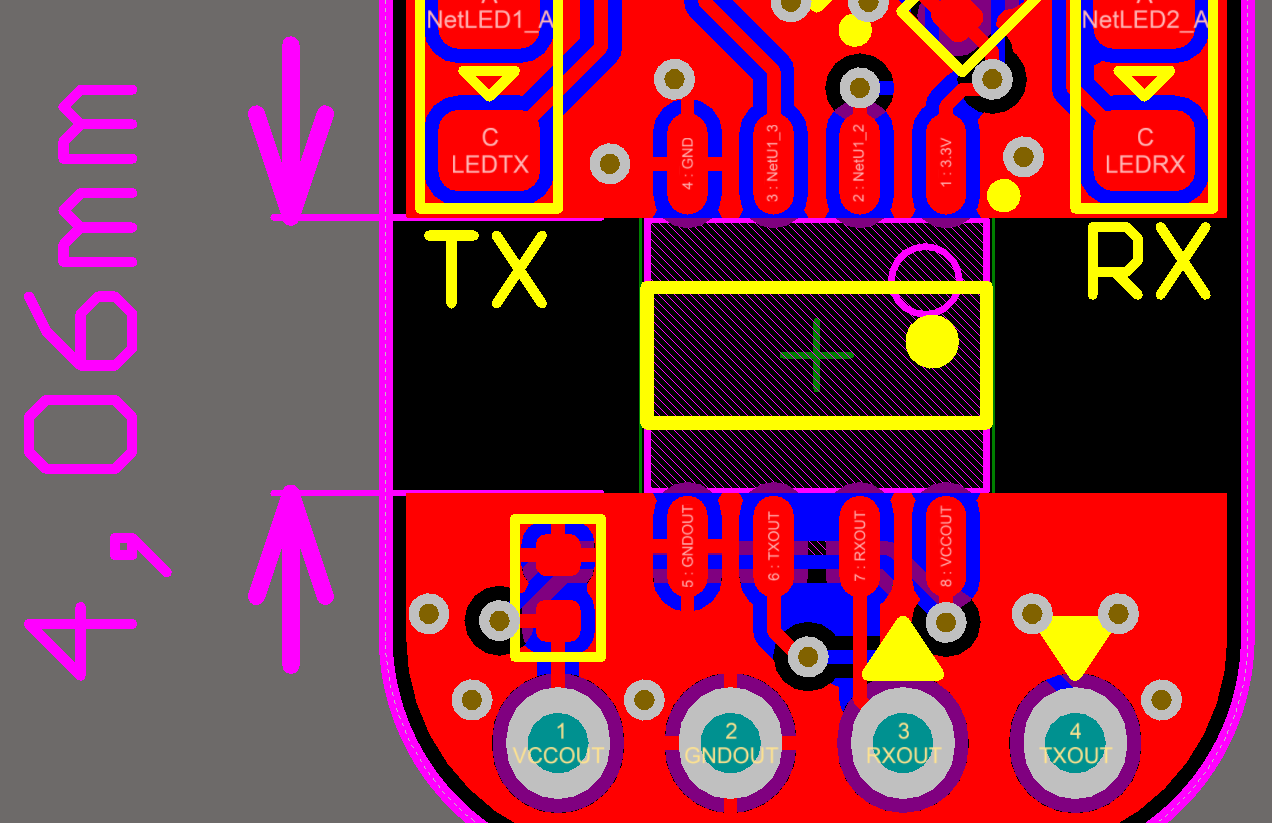
    Unfortunately we discovered a problem with the PCB layout.
    The clearance was not meeting the requirement for the high voltage insulation.
    For this reason we made a new PCB layout with 4mm clearance, enough for isolating up to 1kV.


View all 5 project logs

Enjoy this project?

Share

Discussions

Similar Projects

Does this project spark your interest?

Become a member to follow this project and never miss any updates