Carbon
-
For further updates...
10/13/2014 at 18:04 • 2 commentsFor further updates follow along at my website, appliedcarbon.org.
I'll probably still answer questions and comments here but all the action will be over there from now on.
Thanks for watching!
-
More progress!
08/19/2014 at 21:21 • 0 commentsStill not the spacecraft.
Fixed the servo board! Turns out it was user error: I had the Read/#Write line plugged into #IRQ pin on the XPAN connector - they're right next to each other. (I need a test rig for my test rig?) I guess the crosstalk was clean enough at power up to trigger the register twice.
Speaking of test rigs:
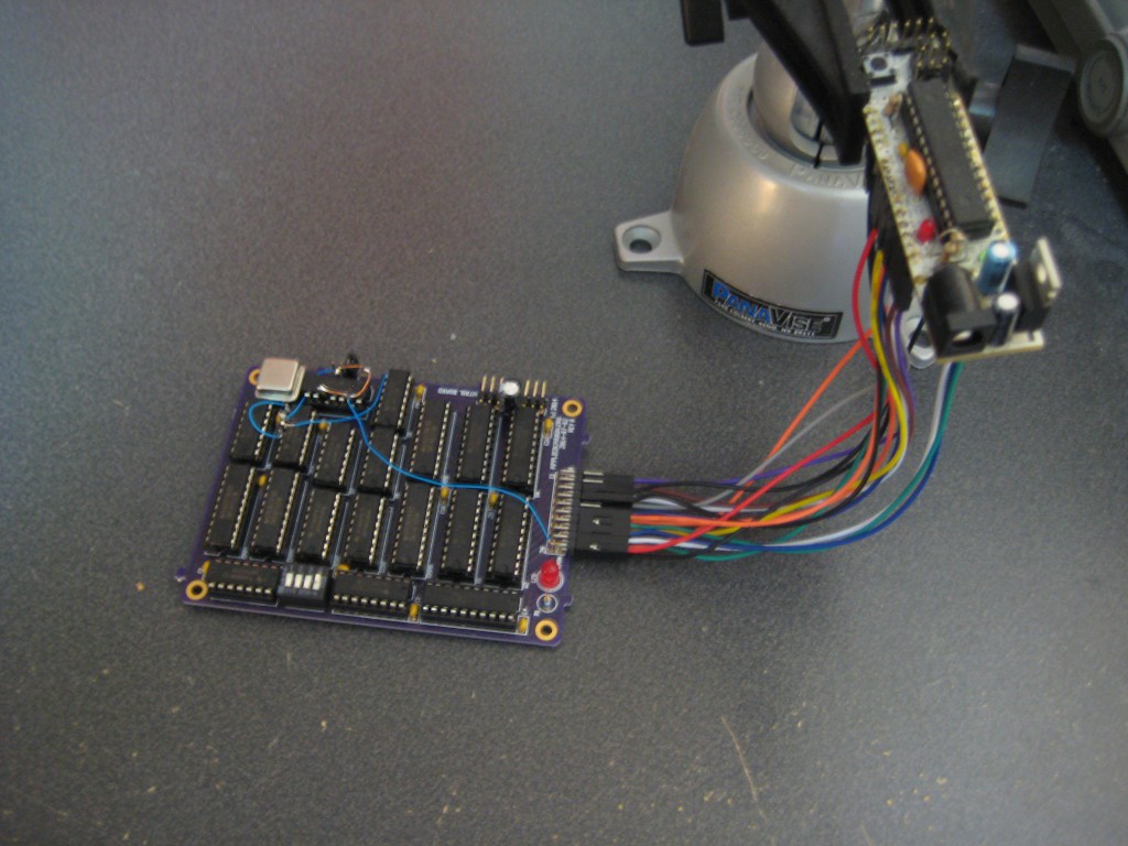
![]() PanaVise FTW.
PanaVise FTW.That's an Adafruit Boarduino from, like, forever ago. That and an (Adafruit) USBTinyISP programmer have been my standby prototype equipment for a long time now.
-
Weird bug on the servo board
08/13/2014 at 18:39 • 0 commentsStill working on the servo board.
I've run into an interesting bug. The data inputs from the bus are doubled buffered so the controller doesn't swap out the compare value part way through a cycle and cause glitches in the output waveform. The buffers are two eight bit registers, one clocked on the data from the expansion bus and the other clocked on the counter reset conditions.
The first register, the one that holds data from the expansion bus, clocks in data exactly twice and then refuses to clock in new data (or at least refuses to show it on the outputs) for at least the next few minutes (that's as long as I've tested it).
I've verified with a logic analyser that the clock and data input signals appear as expected, and the problem exists with both channels on the board (so I don't think it's a bad part). It's repeatable as well; I power cycle the board and the same thing happens every time.
I'm stumped; anybody have any ideas or things to try?
-
DEFCON 22
08/05/2014 at 17:25 • 1 commentI'll be in the hardware hacking village ('natch) for a few hours at least. See you there!
-
Progress!
08/03/2014 at 19:00 • 0 commentsNo, not the spacecraft.
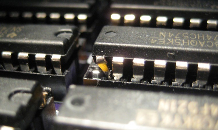
First off, can you spot the problem in this photo?
![]()
Yeah, I don't know how that happened. That's an eight bit register and it's clock pin is jammed into output D7.
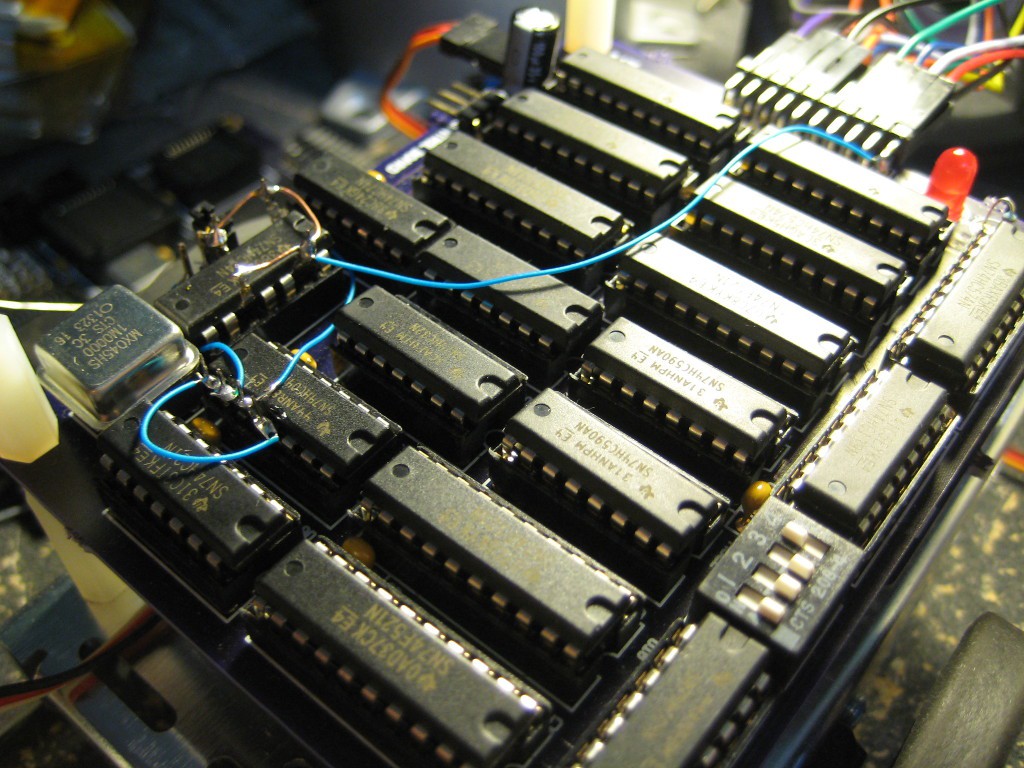
I also discovered that the clear and set pins on the clock divider had been left floating (whoops). I tied those to Vcc and suddenly I have a nice stable clock signal again:
![]()
I had a theory earlier that the signal from the oscillator wasn't as clean as I would expect, so I wired its output through two spare stages on a hex inverter - hence the extra wires in the lower left. I didn't bother removing them; if it works, don't eff with it.
This board still doesn't work however. It'll move a servo attached to channel A exactly twice before the register I'm using to buffer signals from the bus suddenly stops propagating changes. Same thing happens on B channel as well, so it's not a bad chip or anything. No idea what's going wrong with it.
I feel compelled to point out that the 6502sbc is in working condition. I had been tinkering with that design for about a year and it is mostly functional - I can run software and output data on the UART.
Mostly. The UART is still giving me some issues (it works...intermittently), but I think I may have tracked that down.
-
Servo testing woes
08/01/2014 at 18:15 • 0 commentsThe servo control board works...sort of. I can alter the state of the status LED quite easily and drive a servo motor, but they quickly lose functionally. About a minute after power-on any attached servo start acting erraticly and becomes unresponsive. A check with a logic analyser shows that the 74HC74 (dual D-type flip-flop) I'm using as a clock divider works initially but quickly looses it's mind and starts spewing what looks like random noise. Adding extra caps and swapping out the part doesn't seem to help. I'm beginning to suspect I may have missed a critical design detail somewhere. I'd love to have an o-scope to see more detail of what's going on - might actually buy one just for this project.
6502sbc Robot
65C02-based SBC with a discreet-part servo controller and ADC intended as a intermediate-skill learning tool.
 PanaVise FTW.