SirClover
-
Demonstration video
08/17/2014 at 17:12 • 0 commentsIn this video you can see the full project running.
-
Schematic and PCB design
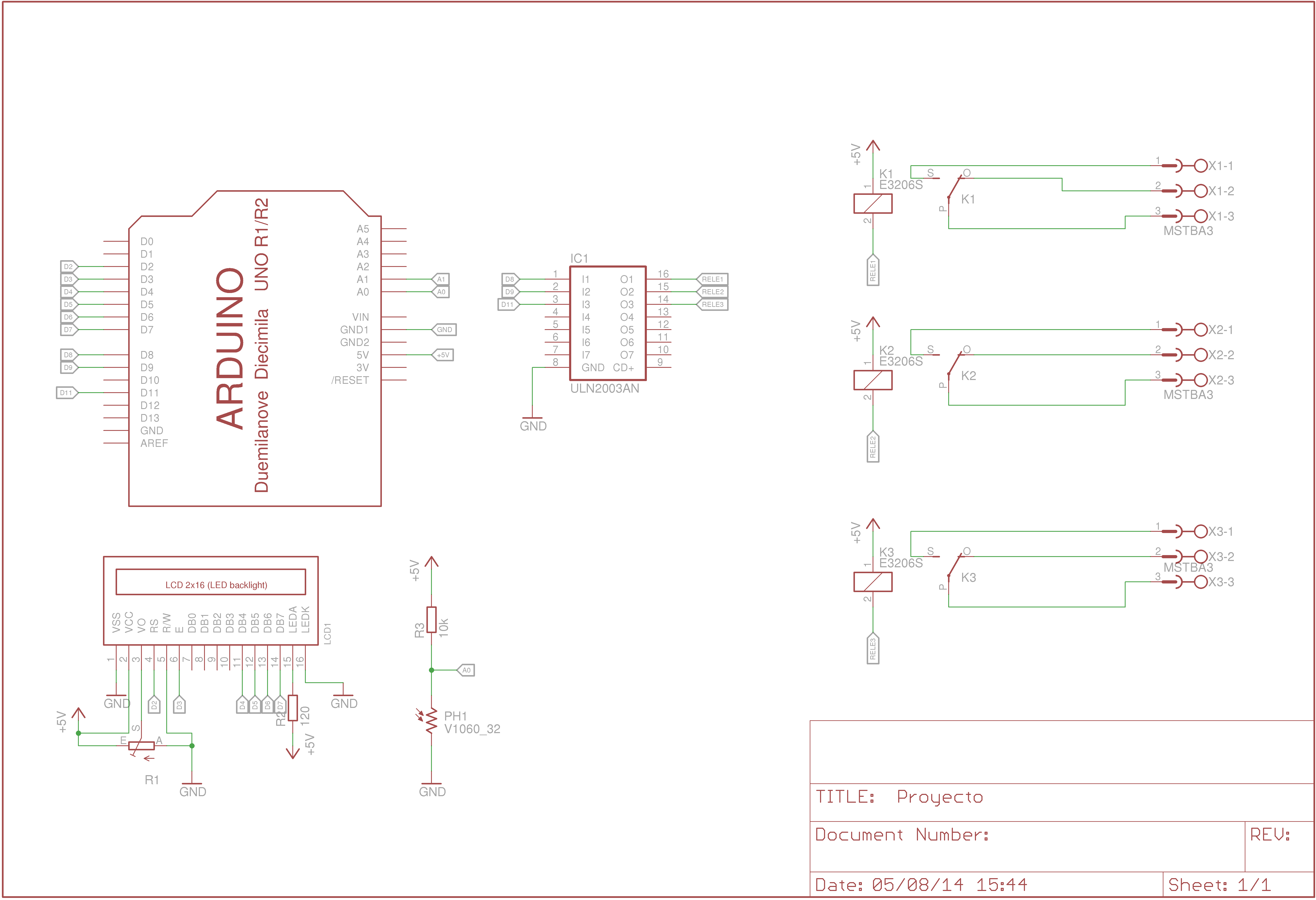
08/17/2014 at 17:10 • 0 commentsThis is the schematic.
![]()
In this image you can see the connections of the parts of the PCB.
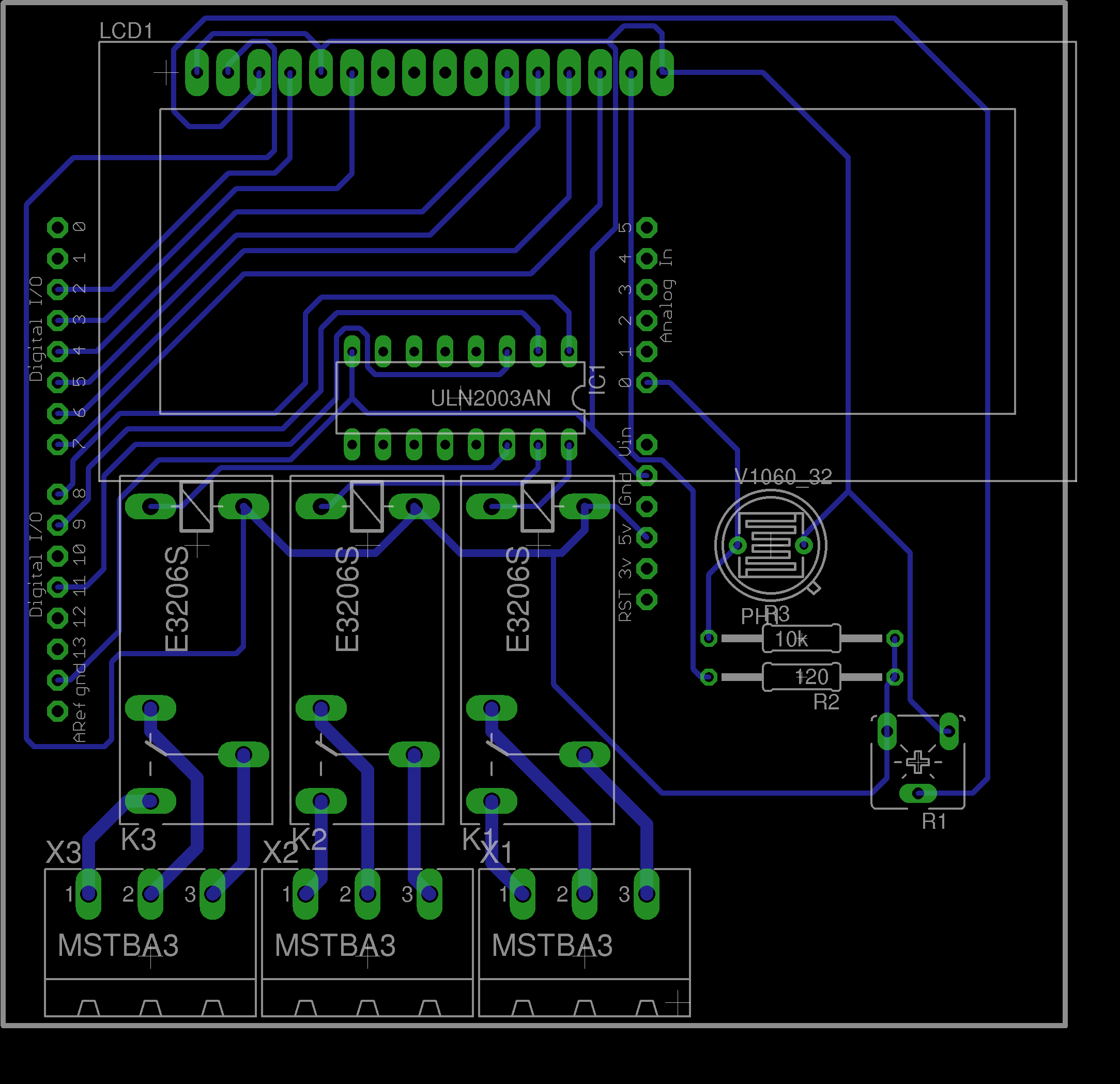
This is the PCB design.
![]()
In this image you can see the distribution of the components in the PCB.
-
Presentation video
08/17/2014 at 17:07 • 0 commentsThis is the video where is explained the idea of the project.
-
System design
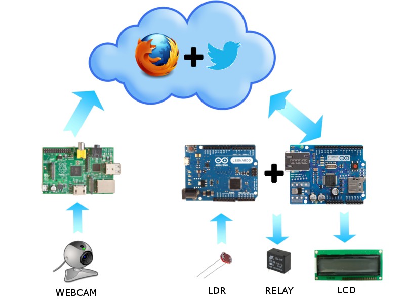
08/17/2014 at 15:35 • 0 commentsThis is the system design.
![]()
In this picture, as you can see, in the part of Arduino, it has connected:
- LDR: to measure the amount of ambiental light.
- RELAY: to activate or deactivate the outputs of the PCB.
- LCD: to show the messages about the state of the PCB.
In the part of Raspberry Pi it has connected a webcam that allows you to see what happen in the room.
The control of the PCB is based in a local ip that contains a webpage made by Arduino with the Ethernet Shield.
To see the streaming of the video you have to access to the Raspberry's local ip at the port 8081.
All the modifications made in the PCB are notificated to the Twitter account.
Home automation system with Twitter
Home automation system with video surveillance that indicates state by tweet.